WO2013122083A1 - 熱可塑性樹脂材の溶着装置、溶着方法、および溶着装置用の押圧ユニット - Google Patents
熱可塑性樹脂材の溶着装置、溶着方法、および溶着装置用の押圧ユニット Download PDFInfo
- Publication number
- WO2013122083A1 WO2013122083A1 PCT/JP2013/053349 JP2013053349W WO2013122083A1 WO 2013122083 A1 WO2013122083 A1 WO 2013122083A1 JP 2013053349 W JP2013053349 W JP 2013053349W WO 2013122083 A1 WO2013122083 A1 WO 2013122083A1
- Authority
- WO
- WIPO (PCT)
- Prior art keywords
- thermoplastic resin
- resin material
- pressure
- welding
- compression
- Prior art date
- Legal status (The legal status is an assumption and is not a legal conclusion. Google has not performed a legal analysis and makes no representation as to the accuracy of the status listed.)
- Ceased
Links
Images











Classifications
-
- B—PERFORMING OPERATIONS; TRANSPORTING
- B29—WORKING OF PLASTICS; WORKING OF SUBSTANCES IN A PLASTIC STATE IN GENERAL
- B29C—SHAPING OR JOINING OF PLASTICS; SHAPING OF MATERIAL IN A PLASTIC STATE, NOT OTHERWISE PROVIDED FOR; AFTER-TREATMENT OF THE SHAPED PRODUCTS, e.g. REPAIRING
- B29C65/00—Joining or sealing of preformed parts, e.g. welding of plastics materials; Apparatus therefor
- B29C65/02—Joining or sealing of preformed parts, e.g. welding of plastics materials; Apparatus therefor by heating, with or without pressure
-
- B—PERFORMING OPERATIONS; TRANSPORTING
- B29—WORKING OF PLASTICS; WORKING OF SUBSTANCES IN A PLASTIC STATE IN GENERAL
- B29C—SHAPING OR JOINING OF PLASTICS; SHAPING OF MATERIAL IN A PLASTIC STATE, NOT OTHERWISE PROVIDED FOR; AFTER-TREATMENT OF THE SHAPED PRODUCTS, e.g. REPAIRING
- B29C35/00—Heating, cooling or curing, e.g. crosslinking or vulcanising; Apparatus therefor
- B29C35/02—Heating or curing, e.g. crosslinking or vulcanizing during moulding, e.g. in a mould
- B29C35/04—Heating or curing, e.g. crosslinking or vulcanizing during moulding, e.g. in a mould using liquids, gas or steam
- B29C35/041—Heating or curing, e.g. crosslinking or vulcanizing during moulding, e.g. in a mould using liquids, gas or steam using liquids
-
- B—PERFORMING OPERATIONS; TRANSPORTING
- B29—WORKING OF PLASTICS; WORKING OF SUBSTANCES IN A PLASTIC STATE IN GENERAL
- B29C—SHAPING OR JOINING OF PLASTICS; SHAPING OF MATERIAL IN A PLASTIC STATE, NOT OTHERWISE PROVIDED FOR; AFTER-TREATMENT OF THE SHAPED PRODUCTS, e.g. REPAIRING
- B29C35/00—Heating, cooling or curing, e.g. crosslinking or vulcanising; Apparatus therefor
- B29C35/02—Heating or curing, e.g. crosslinking or vulcanizing during moulding, e.g. in a mould
- B29C35/04—Heating or curing, e.g. crosslinking or vulcanizing during moulding, e.g. in a mould using liquids, gas or steam
- B29C35/045—Heating or curing, e.g. crosslinking or vulcanizing during moulding, e.g. in a mould using liquids, gas or steam using gas or flames
-
- B—PERFORMING OPERATIONS; TRANSPORTING
- B29—WORKING OF PLASTICS; WORKING OF SUBSTANCES IN A PLASTIC STATE IN GENERAL
- B29C—SHAPING OR JOINING OF PLASTICS; SHAPING OF MATERIAL IN A PLASTIC STATE, NOT OTHERWISE PROVIDED FOR; AFTER-TREATMENT OF THE SHAPED PRODUCTS, e.g. REPAIRING
- B29C35/00—Heating, cooling or curing, e.g. crosslinking or vulcanising; Apparatus therefor
- B29C35/02—Heating or curing, e.g. crosslinking or vulcanizing during moulding, e.g. in a mould
- B29C35/08—Heating or curing, e.g. crosslinking or vulcanizing during moulding, e.g. in a mould by wave energy or particle radiation
- B29C35/0805—Heating or curing, e.g. crosslinking or vulcanizing during moulding, e.g. in a mould by wave energy or particle radiation using electromagnetic radiation
-
- B—PERFORMING OPERATIONS; TRANSPORTING
- B29—WORKING OF PLASTICS; WORKING OF SUBSTANCES IN A PLASTIC STATE IN GENERAL
- B29C—SHAPING OR JOINING OF PLASTICS; SHAPING OF MATERIAL IN A PLASTIC STATE, NOT OTHERWISE PROVIDED FOR; AFTER-TREATMENT OF THE SHAPED PRODUCTS, e.g. REPAIRING
- B29C65/00—Joining or sealing of preformed parts, e.g. welding of plastics materials; Apparatus therefor
- B29C65/02—Joining or sealing of preformed parts, e.g. welding of plastics materials; Apparatus therefor by heating, with or without pressure
- B29C65/14—Joining or sealing of preformed parts, e.g. welding of plastics materials; Apparatus therefor by heating, with or without pressure using wave energy, i.e. electromagnetic radiation, or particle radiation
-
- B—PERFORMING OPERATIONS; TRANSPORTING
- B29—WORKING OF PLASTICS; WORKING OF SUBSTANCES IN A PLASTIC STATE IN GENERAL
- B29C—SHAPING OR JOINING OF PLASTICS; SHAPING OF MATERIAL IN A PLASTIC STATE, NOT OTHERWISE PROVIDED FOR; AFTER-TREATMENT OF THE SHAPED PRODUCTS, e.g. REPAIRING
- B29C65/00—Joining or sealing of preformed parts, e.g. welding of plastics materials; Apparatus therefor
- B29C65/02—Joining or sealing of preformed parts, e.g. welding of plastics materials; Apparatus therefor by heating, with or without pressure
- B29C65/14—Joining or sealing of preformed parts, e.g. welding of plastics materials; Apparatus therefor by heating, with or without pressure using wave energy, i.e. electromagnetic radiation, or particle radiation
- B29C65/16—Laser beams
-
- B—PERFORMING OPERATIONS; TRANSPORTING
- B29—WORKING OF PLASTICS; WORKING OF SUBSTANCES IN A PLASTIC STATE IN GENERAL
- B29C—SHAPING OR JOINING OF PLASTICS; SHAPING OF MATERIAL IN A PLASTIC STATE, NOT OTHERWISE PROVIDED FOR; AFTER-TREATMENT OF THE SHAPED PRODUCTS, e.g. REPAIRING
- B29C65/00—Joining or sealing of preformed parts, e.g. welding of plastics materials; Apparatus therefor
- B29C65/02—Joining or sealing of preformed parts, e.g. welding of plastics materials; Apparatus therefor by heating, with or without pressure
- B29C65/14—Joining or sealing of preformed parts, e.g. welding of plastics materials; Apparatus therefor by heating, with or without pressure using wave energy, i.e. electromagnetic radiation, or particle radiation
- B29C65/16—Laser beams
- B29C65/1629—Laser beams characterised by the way of heating the interface
- B29C65/1635—Laser beams characterised by the way of heating the interface at least passing through one of the parts to be joined, i.e. laser transmission welding
-
- B—PERFORMING OPERATIONS; TRANSPORTING
- B29—WORKING OF PLASTICS; WORKING OF SUBSTANCES IN A PLASTIC STATE IN GENERAL
- B29C—SHAPING OR JOINING OF PLASTICS; SHAPING OF MATERIAL IN A PLASTIC STATE, NOT OTHERWISE PROVIDED FOR; AFTER-TREATMENT OF THE SHAPED PRODUCTS, e.g. REPAIRING
- B29C65/00—Joining or sealing of preformed parts, e.g. welding of plastics materials; Apparatus therefor
- B29C65/02—Joining or sealing of preformed parts, e.g. welding of plastics materials; Apparatus therefor by heating, with or without pressure
- B29C65/14—Joining or sealing of preformed parts, e.g. welding of plastics materials; Apparatus therefor by heating, with or without pressure using wave energy, i.e. electromagnetic radiation, or particle radiation
- B29C65/16—Laser beams
- B29C65/1629—Laser beams characterised by the way of heating the interface
- B29C65/1654—Laser beams characterised by the way of heating the interface scanning at least one of the parts to be joined
-
- B—PERFORMING OPERATIONS; TRANSPORTING
- B29—WORKING OF PLASTICS; WORKING OF SUBSTANCES IN A PLASTIC STATE IN GENERAL
- B29C—SHAPING OR JOINING OF PLASTICS; SHAPING OF MATERIAL IN A PLASTIC STATE, NOT OTHERWISE PROVIDED FOR; AFTER-TREATMENT OF THE SHAPED PRODUCTS, e.g. REPAIRING
- B29C65/00—Joining or sealing of preformed parts, e.g. welding of plastics materials; Apparatus therefor
- B29C65/02—Joining or sealing of preformed parts, e.g. welding of plastics materials; Apparatus therefor by heating, with or without pressure
- B29C65/18—Joining or sealing of preformed parts, e.g. welding of plastics materials; Apparatus therefor by heating, with or without pressure using heated tools
-
- B—PERFORMING OPERATIONS; TRANSPORTING
- B29—WORKING OF PLASTICS; WORKING OF SUBSTANCES IN A PLASTIC STATE IN GENERAL
- B29C—SHAPING OR JOINING OF PLASTICS; SHAPING OF MATERIAL IN A PLASTIC STATE, NOT OTHERWISE PROVIDED FOR; AFTER-TREATMENT OF THE SHAPED PRODUCTS, e.g. REPAIRING
- B29C65/00—Joining or sealing of preformed parts, e.g. welding of plastics materials; Apparatus therefor
- B29C65/02—Joining or sealing of preformed parts, e.g. welding of plastics materials; Apparatus therefor by heating, with or without pressure
- B29C65/18—Joining or sealing of preformed parts, e.g. welding of plastics materials; Apparatus therefor by heating, with or without pressure using heated tools
- B29C65/24—Joining or sealing of preformed parts, e.g. welding of plastics materials; Apparatus therefor by heating, with or without pressure using heated tools characterised by the means for heating the tool
- B29C65/245—Joining or sealing of preformed parts, e.g. welding of plastics materials; Apparatus therefor by heating, with or without pressure using heated tools characterised by the means for heating the tool the heat transfer being achieved contactless, e.g. by radiation
-
- B—PERFORMING OPERATIONS; TRANSPORTING
- B29—WORKING OF PLASTICS; WORKING OF SUBSTANCES IN A PLASTIC STATE IN GENERAL
- B29C—SHAPING OR JOINING OF PLASTICS; SHAPING OF MATERIAL IN A PLASTIC STATE, NOT OTHERWISE PROVIDED FOR; AFTER-TREATMENT OF THE SHAPED PRODUCTS, e.g. REPAIRING
- B29C65/00—Joining or sealing of preformed parts, e.g. welding of plastics materials; Apparatus therefor
- B29C65/02—Joining or sealing of preformed parts, e.g. welding of plastics materials; Apparatus therefor by heating, with or without pressure
- B29C65/18—Joining or sealing of preformed parts, e.g. welding of plastics materials; Apparatus therefor by heating, with or without pressure using heated tools
- B29C65/24—Joining or sealing of preformed parts, e.g. welding of plastics materials; Apparatus therefor by heating, with or without pressure using heated tools characterised by the means for heating the tool
- B29C65/30—Electrical means
- B29C65/32—Induction
-
- B—PERFORMING OPERATIONS; TRANSPORTING
- B29—WORKING OF PLASTICS; WORKING OF SUBSTANCES IN A PLASTIC STATE IN GENERAL
- B29C—SHAPING OR JOINING OF PLASTICS; SHAPING OF MATERIAL IN A PLASTIC STATE, NOT OTHERWISE PROVIDED FOR; AFTER-TREATMENT OF THE SHAPED PRODUCTS, e.g. REPAIRING
- B29C65/00—Joining or sealing of preformed parts, e.g. welding of plastics materials; Apparatus therefor
- B29C65/78—Means for handling the parts to be joined, e.g. for making containers or hollow articles, e.g. means for handling sheets, plates, web-like materials, tubular articles, hollow articles or elements to be joined therewith; Means for discharging the joined articles from the joining apparatus
- B29C65/7802—Positioning the parts to be joined, e.g. aligning, indexing or centring
-
- B—PERFORMING OPERATIONS; TRANSPORTING
- B29—WORKING OF PLASTICS; WORKING OF SUBSTANCES IN A PLASTIC STATE IN GENERAL
- B29C—SHAPING OR JOINING OF PLASTICS; SHAPING OF MATERIAL IN A PLASTIC STATE, NOT OTHERWISE PROVIDED FOR; AFTER-TREATMENT OF THE SHAPED PRODUCTS, e.g. REPAIRING
- B29C66/00—General aspects of processes or apparatus for joining preformed parts
- B29C66/01—General aspects dealing with the joint area or with the area to be joined
- B29C66/05—Particular design of joint configurations
- B29C66/10—Particular design of joint configurations particular design of the joint cross-sections
- B29C66/11—Joint cross-sections comprising a single joint-segment, i.e. one of the parts to be joined comprising a single joint-segment in the joint cross-section
- B29C66/112—Single lapped joints
- B29C66/1122—Single lap to lap joints, i.e. overlap joints
-
- B—PERFORMING OPERATIONS; TRANSPORTING
- B29—WORKING OF PLASTICS; WORKING OF SUBSTANCES IN A PLASTIC STATE IN GENERAL
- B29C—SHAPING OR JOINING OF PLASTICS; SHAPING OF MATERIAL IN A PLASTIC STATE, NOT OTHERWISE PROVIDED FOR; AFTER-TREATMENT OF THE SHAPED PRODUCTS, e.g. REPAIRING
- B29C66/00—General aspects of processes or apparatus for joining preformed parts
- B29C66/01—General aspects dealing with the joint area or with the area to be joined
- B29C66/05—Particular design of joint configurations
- B29C66/10—Particular design of joint configurations particular design of the joint cross-sections
- B29C66/11—Joint cross-sections comprising a single joint-segment, i.e. one of the parts to be joined comprising a single joint-segment in the joint cross-section
- B29C66/114—Single butt joints
- B29C66/1142—Single butt to butt joints
-
- B—PERFORMING OPERATIONS; TRANSPORTING
- B29—WORKING OF PLASTICS; WORKING OF SUBSTANCES IN A PLASTIC STATE IN GENERAL
- B29C—SHAPING OR JOINING OF PLASTICS; SHAPING OF MATERIAL IN A PLASTIC STATE, NOT OTHERWISE PROVIDED FOR; AFTER-TREATMENT OF THE SHAPED PRODUCTS, e.g. REPAIRING
- B29C66/00—General aspects of processes or apparatus for joining preformed parts
- B29C66/01—General aspects dealing with the joint area or with the area to be joined
- B29C66/342—Preventing air-inclusions
-
- B—PERFORMING OPERATIONS; TRANSPORTING
- B29—WORKING OF PLASTICS; WORKING OF SUBSTANCES IN A PLASTIC STATE IN GENERAL
- B29C—SHAPING OR JOINING OF PLASTICS; SHAPING OF MATERIAL IN A PLASTIC STATE, NOT OTHERWISE PROVIDED FOR; AFTER-TREATMENT OF THE SHAPED PRODUCTS, e.g. REPAIRING
- B29C66/00—General aspects of processes or apparatus for joining preformed parts
- B29C66/01—General aspects dealing with the joint area or with the area to be joined
- B29C66/345—Progressively making the joint, e.g. starting from the middle
-
- B—PERFORMING OPERATIONS; TRANSPORTING
- B29—WORKING OF PLASTICS; WORKING OF SUBSTANCES IN A PLASTIC STATE IN GENERAL
- B29C—SHAPING OR JOINING OF PLASTICS; SHAPING OF MATERIAL IN A PLASTIC STATE, NOT OTHERWISE PROVIDED FOR; AFTER-TREATMENT OF THE SHAPED PRODUCTS, e.g. REPAIRING
- B29C66/00—General aspects of processes or apparatus for joining preformed parts
- B29C66/40—General aspects of joining substantially flat articles, e.g. plates, sheets or web-like materials; Making flat seams in tubular or hollow articles; Joining single elements to substantially flat surfaces
- B29C66/41—Joining substantially flat articles ; Making flat seams in tubular or hollow articles
- B29C66/43—Joining a relatively small portion of the surface of said articles
- B29C66/432—Joining a relatively small portion of the surface of said articles for making tubular articles or closed loops, e.g. by joining several sheets ; for making hollow articles or hollow preforms
- B29C66/4322—Joining a relatively small portion of the surface of said articles for making tubular articles or closed loops, e.g. by joining several sheets ; for making hollow articles or hollow preforms by joining a single sheet to itself
-
- B—PERFORMING OPERATIONS; TRANSPORTING
- B29—WORKING OF PLASTICS; WORKING OF SUBSTANCES IN A PLASTIC STATE IN GENERAL
- B29C—SHAPING OR JOINING OF PLASTICS; SHAPING OF MATERIAL IN A PLASTIC STATE, NOT OTHERWISE PROVIDED FOR; AFTER-TREATMENT OF THE SHAPED PRODUCTS, e.g. REPAIRING
- B29C66/00—General aspects of processes or apparatus for joining preformed parts
- B29C66/40—General aspects of joining substantially flat articles, e.g. plates, sheets or web-like materials; Making flat seams in tubular or hollow articles; Joining single elements to substantially flat surfaces
- B29C66/41—Joining substantially flat articles ; Making flat seams in tubular or hollow articles
- B29C66/43—Joining a relatively small portion of the surface of said articles
- B29C66/432—Joining a relatively small portion of the surface of said articles for making tubular articles or closed loops, e.g. by joining several sheets ; for making hollow articles or hollow preforms
- B29C66/4329—Joining a relatively small portion of the surface of said articles for making tubular articles or closed loops, e.g. by joining several sheets ; for making hollow articles or hollow preforms the joint lines being transversal but non-orthogonal with respect to the axis of said tubular articles, i.e. being oblique
-
- B—PERFORMING OPERATIONS; TRANSPORTING
- B29—WORKING OF PLASTICS; WORKING OF SUBSTANCES IN A PLASTIC STATE IN GENERAL
- B29C—SHAPING OR JOINING OF PLASTICS; SHAPING OF MATERIAL IN A PLASTIC STATE, NOT OTHERWISE PROVIDED FOR; AFTER-TREATMENT OF THE SHAPED PRODUCTS, e.g. REPAIRING
- B29C66/00—General aspects of processes or apparatus for joining preformed parts
- B29C66/40—General aspects of joining substantially flat articles, e.g. plates, sheets or web-like materials; Making flat seams in tubular or hollow articles; Joining single elements to substantially flat surfaces
- B29C66/49—Internally supporting the, e.g. tubular, article during joining
-
- B—PERFORMING OPERATIONS; TRANSPORTING
- B29—WORKING OF PLASTICS; WORKING OF SUBSTANCES IN A PLASTIC STATE IN GENERAL
- B29C—SHAPING OR JOINING OF PLASTICS; SHAPING OF MATERIAL IN A PLASTIC STATE, NOT OTHERWISE PROVIDED FOR; AFTER-TREATMENT OF THE SHAPED PRODUCTS, e.g. REPAIRING
- B29C66/00—General aspects of processes or apparatus for joining preformed parts
- B29C66/50—General aspects of joining tubular articles; General aspects of joining long products, i.e. bars or profiled elements; General aspects of joining single elements to tubular articles, hollow articles or bars; General aspects of joining several hollow-preforms to form hollow or tubular articles
- B29C66/51—Joining tubular articles, profiled elements or bars; Joining single elements to tubular articles, hollow articles or bars; Joining several hollow-preforms to form hollow or tubular articles
- B29C66/52—Joining tubular articles, bars or profiled elements
- B29C66/522—Joining tubular articles
- B29C66/5221—Joining tubular articles for forming coaxial connections, i.e. the tubular articles to be joined forming a zero angle relative to each other
-
- B—PERFORMING OPERATIONS; TRANSPORTING
- B29—WORKING OF PLASTICS; WORKING OF SUBSTANCES IN A PLASTIC STATE IN GENERAL
- B29C—SHAPING OR JOINING OF PLASTICS; SHAPING OF MATERIAL IN A PLASTIC STATE, NOT OTHERWISE PROVIDED FOR; AFTER-TREATMENT OF THE SHAPED PRODUCTS, e.g. REPAIRING
- B29C66/00—General aspects of processes or apparatus for joining preformed parts
- B29C66/50—General aspects of joining tubular articles; General aspects of joining long products, i.e. bars or profiled elements; General aspects of joining single elements to tubular articles, hollow articles or bars; General aspects of joining several hollow-preforms to form hollow or tubular articles
- B29C66/61—Joining from or joining on the inside
- B29C66/612—Making circumferential joints
-
- B—PERFORMING OPERATIONS; TRANSPORTING
- B29—WORKING OF PLASTICS; WORKING OF SUBSTANCES IN A PLASTIC STATE IN GENERAL
- B29C—SHAPING OR JOINING OF PLASTICS; SHAPING OF MATERIAL IN A PLASTIC STATE, NOT OTHERWISE PROVIDED FOR; AFTER-TREATMENT OF THE SHAPED PRODUCTS, e.g. REPAIRING
- B29C66/00—General aspects of processes or apparatus for joining preformed parts
- B29C66/50—General aspects of joining tubular articles; General aspects of joining long products, i.e. bars or profiled elements; General aspects of joining single elements to tubular articles, hollow articles or bars; General aspects of joining several hollow-preforms to form hollow or tubular articles
- B29C66/63—Internally supporting the article during joining
-
- B—PERFORMING OPERATIONS; TRANSPORTING
- B29—WORKING OF PLASTICS; WORKING OF SUBSTANCES IN A PLASTIC STATE IN GENERAL
- B29C—SHAPING OR JOINING OF PLASTICS; SHAPING OF MATERIAL IN A PLASTIC STATE, NOT OTHERWISE PROVIDED FOR; AFTER-TREATMENT OF THE SHAPED PRODUCTS, e.g. REPAIRING
- B29C66/00—General aspects of processes or apparatus for joining preformed parts
- B29C66/50—General aspects of joining tubular articles; General aspects of joining long products, i.e. bars or profiled elements; General aspects of joining single elements to tubular articles, hollow articles or bars; General aspects of joining several hollow-preforms to form hollow or tubular articles
- B29C66/63—Internally supporting the article during joining
- B29C66/634—Internally supporting the article during joining using an inflatable core
-
- B—PERFORMING OPERATIONS; TRANSPORTING
- B29—WORKING OF PLASTICS; WORKING OF SUBSTANCES IN A PLASTIC STATE IN GENERAL
- B29C—SHAPING OR JOINING OF PLASTICS; SHAPING OF MATERIAL IN A PLASTIC STATE, NOT OTHERWISE PROVIDED FOR; AFTER-TREATMENT OF THE SHAPED PRODUCTS, e.g. REPAIRING
- B29C66/00—General aspects of processes or apparatus for joining preformed parts
- B29C66/50—General aspects of joining tubular articles; General aspects of joining long products, i.e. bars or profiled elements; General aspects of joining single elements to tubular articles, hollow articles or bars; General aspects of joining several hollow-preforms to form hollow or tubular articles
- B29C66/65—General aspects of joining tubular articles; General aspects of joining long products, i.e. bars or profiled elements; General aspects of joining single elements to tubular articles, hollow articles or bars; General aspects of joining several hollow-preforms to form hollow or tubular articles with a relative motion between the article and the welding tool
-
- B—PERFORMING OPERATIONS; TRANSPORTING
- B29—WORKING OF PLASTICS; WORKING OF SUBSTANCES IN A PLASTIC STATE IN GENERAL
- B29C—SHAPING OR JOINING OF PLASTICS; SHAPING OF MATERIAL IN A PLASTIC STATE, NOT OTHERWISE PROVIDED FOR; AFTER-TREATMENT OF THE SHAPED PRODUCTS, e.g. REPAIRING
- B29C66/00—General aspects of processes or apparatus for joining preformed parts
- B29C66/70—General aspects of processes or apparatus for joining preformed parts characterised by the composition, physical properties or the structure of the material of the parts to be joined; Joining with non-plastics material
- B29C66/73—General aspects of processes or apparatus for joining preformed parts characterised by the composition, physical properties or the structure of the material of the parts to be joined; Joining with non-plastics material characterised by the intensive physical properties of the material of the parts to be joined, by the optical properties of the material of the parts to be joined, by the extensive physical properties of the parts to be joined, by the state of the material of the parts to be joined or by the material of the parts to be joined being a thermoplastic or a thermoset
- B29C66/735—General aspects of processes or apparatus for joining preformed parts characterised by the composition, physical properties or the structure of the material of the parts to be joined; Joining with non-plastics material characterised by the intensive physical properties of the material of the parts to be joined, by the optical properties of the material of the parts to be joined, by the extensive physical properties of the parts to be joined, by the state of the material of the parts to be joined or by the material of the parts to be joined being a thermoplastic or a thermoset characterised by the extensive physical properties of the parts to be joined
- B29C66/7352—Thickness, e.g. very thin
- B29C66/73521—Thickness, e.g. very thin of different thickness, i.e. the thickness of one of the parts to be joined being different from the thickness of the other part
-
- B—PERFORMING OPERATIONS; TRANSPORTING
- B29—WORKING OF PLASTICS; WORKING OF SUBSTANCES IN A PLASTIC STATE IN GENERAL
- B29C—SHAPING OR JOINING OF PLASTICS; SHAPING OF MATERIAL IN A PLASTIC STATE, NOT OTHERWISE PROVIDED FOR; AFTER-TREATMENT OF THE SHAPED PRODUCTS, e.g. REPAIRING
- B29C66/00—General aspects of processes or apparatus for joining preformed parts
- B29C66/70—General aspects of processes or apparatus for joining preformed parts characterised by the composition, physical properties or the structure of the material of the parts to be joined; Joining with non-plastics material
- B29C66/73—General aspects of processes or apparatus for joining preformed parts characterised by the composition, physical properties or the structure of the material of the parts to be joined; Joining with non-plastics material characterised by the intensive physical properties of the material of the parts to be joined, by the optical properties of the material of the parts to be joined, by the extensive physical properties of the parts to be joined, by the state of the material of the parts to be joined or by the material of the parts to be joined being a thermoplastic or a thermoset
- B29C66/739—General aspects of processes or apparatus for joining preformed parts characterised by the composition, physical properties or the structure of the material of the parts to be joined; Joining with non-plastics material characterised by the intensive physical properties of the material of the parts to be joined, by the optical properties of the material of the parts to be joined, by the extensive physical properties of the parts to be joined, by the state of the material of the parts to be joined or by the material of the parts to be joined being a thermoplastic or a thermoset characterised by the material of the parts to be joined being a thermoplastic or a thermoset
- B29C66/7392—General aspects of processes or apparatus for joining preformed parts characterised by the composition, physical properties or the structure of the material of the parts to be joined; Joining with non-plastics material characterised by the intensive physical properties of the material of the parts to be joined, by the optical properties of the material of the parts to be joined, by the extensive physical properties of the parts to be joined, by the state of the material of the parts to be joined or by the material of the parts to be joined being a thermoplastic or a thermoset characterised by the material of the parts to be joined being a thermoplastic or a thermoset characterised by the material of at least one of the parts being a thermoplastic
- B29C66/73921—General aspects of processes or apparatus for joining preformed parts characterised by the composition, physical properties or the structure of the material of the parts to be joined; Joining with non-plastics material characterised by the intensive physical properties of the material of the parts to be joined, by the optical properties of the material of the parts to be joined, by the extensive physical properties of the parts to be joined, by the state of the material of the parts to be joined or by the material of the parts to be joined being a thermoplastic or a thermoset characterised by the material of the parts to be joined being a thermoplastic or a thermoset characterised by the material of at least one of the parts being a thermoplastic characterised by the materials of both parts being thermoplastics
-
- B—PERFORMING OPERATIONS; TRANSPORTING
- B29—WORKING OF PLASTICS; WORKING OF SUBSTANCES IN A PLASTIC STATE IN GENERAL
- B29C—SHAPING OR JOINING OF PLASTICS; SHAPING OF MATERIAL IN A PLASTIC STATE, NOT OTHERWISE PROVIDED FOR; AFTER-TREATMENT OF THE SHAPED PRODUCTS, e.g. REPAIRING
- B29C66/00—General aspects of processes or apparatus for joining preformed parts
- B29C66/80—General aspects of machine operations or constructions and parts thereof
- B29C66/81—General aspects of the pressing elements, i.e. the elements applying pressure on the parts to be joined in the area to be joined, e.g. the welding jaws or clamps
- B29C66/812—General aspects of the pressing elements, i.e. the elements applying pressure on the parts to be joined in the area to be joined, e.g. the welding jaws or clamps characterised by the composition, by the structure, by the intensive physical properties or by the optical properties of the material constituting the pressing elements, e.g. constituting the welding jaws or clamps
- B29C66/8126—General aspects of the pressing elements, i.e. the elements applying pressure on the parts to be joined in the area to be joined, e.g. the welding jaws or clamps characterised by the composition, by the structure, by the intensive physical properties or by the optical properties of the material constituting the pressing elements, e.g. constituting the welding jaws or clamps characterised by the intensive physical properties or by the optical properties of the material constituting the pressing elements, e.g. constituting the welding jaws or clamps
- B29C66/81266—Optical properties, e.g. transparency, reflectivity
- B29C66/81267—Transparent to electromagnetic radiation, e.g. to visible light
-
- B—PERFORMING OPERATIONS; TRANSPORTING
- B29—WORKING OF PLASTICS; WORKING OF SUBSTANCES IN A PLASTIC STATE IN GENERAL
- B29C—SHAPING OR JOINING OF PLASTICS; SHAPING OF MATERIAL IN A PLASTIC STATE, NOT OTHERWISE PROVIDED FOR; AFTER-TREATMENT OF THE SHAPED PRODUCTS, e.g. REPAIRING
- B29C66/00—General aspects of processes or apparatus for joining preformed parts
- B29C66/80—General aspects of machine operations or constructions and parts thereof
- B29C66/81—General aspects of the pressing elements, i.e. the elements applying pressure on the parts to be joined in the area to be joined, e.g. the welding jaws or clamps
- B29C66/814—General aspects of the pressing elements, i.e. the elements applying pressure on the parts to be joined in the area to be joined, e.g. the welding jaws or clamps characterised by the design of the pressing elements, e.g. of the welding jaws or clamps
- B29C66/8145—General aspects of the pressing elements, i.e. the elements applying pressure on the parts to be joined in the area to be joined, e.g. the welding jaws or clamps characterised by the design of the pressing elements, e.g. of the welding jaws or clamps characterised by the constructional aspects of the pressing elements, e.g. of the welding jaws or clamps
- B29C66/81455—General aspects of the pressing elements, i.e. the elements applying pressure on the parts to be joined in the area to be joined, e.g. the welding jaws or clamps characterised by the design of the pressing elements, e.g. of the welding jaws or clamps characterised by the constructional aspects of the pressing elements, e.g. of the welding jaws or clamps being a fluid inflatable bag or bladder, a diaphragm or a vacuum bag for applying isostatic pressure
-
- B—PERFORMING OPERATIONS; TRANSPORTING
- B29—WORKING OF PLASTICS; WORKING OF SUBSTANCES IN A PLASTIC STATE IN GENERAL
- B29C—SHAPING OR JOINING OF PLASTICS; SHAPING OF MATERIAL IN A PLASTIC STATE, NOT OTHERWISE PROVIDED FOR; AFTER-TREATMENT OF THE SHAPED PRODUCTS, e.g. REPAIRING
- B29C66/00—General aspects of processes or apparatus for joining preformed parts
- B29C66/90—Measuring or controlling the joining process
- B29C66/91—Measuring or controlling the joining process by measuring or controlling the temperature, the heat or the thermal flux
- B29C66/914—Measuring or controlling the joining process by measuring or controlling the temperature, the heat or the thermal flux by controlling or regulating the temperature, the heat or the thermal flux
- B29C66/9161—Measuring or controlling the joining process by measuring or controlling the temperature, the heat or the thermal flux by controlling or regulating the temperature, the heat or the thermal flux by controlling or regulating the heat or the thermal flux, i.e. the heat flux
- B29C66/91651—Measuring or controlling the joining process by measuring or controlling the temperature, the heat or the thermal flux by controlling or regulating the temperature, the heat or the thermal flux by controlling or regulating the heat or the thermal flux, i.e. the heat flux by controlling or regulating the heat generated by Joule heating or induction heating
-
- B—PERFORMING OPERATIONS; TRANSPORTING
- B29—WORKING OF PLASTICS; WORKING OF SUBSTANCES IN A PLASTIC STATE IN GENERAL
- B29C—SHAPING OR JOINING OF PLASTICS; SHAPING OF MATERIAL IN A PLASTIC STATE, NOT OTHERWISE PROVIDED FOR; AFTER-TREATMENT OF THE SHAPED PRODUCTS, e.g. REPAIRING
- B29C66/00—General aspects of processes or apparatus for joining preformed parts
- B29C66/90—Measuring or controlling the joining process
- B29C66/92—Measuring or controlling the joining process by measuring or controlling the pressure, the force, the mechanical power or the displacement of the joining tools
- B29C66/924—Measuring or controlling the joining process by measuring or controlling the pressure, the force, the mechanical power or the displacement of the joining tools by controlling or regulating the pressure, the force, the mechanical power or the displacement of the joining tools
- B29C66/9241—Measuring or controlling the joining process by measuring or controlling the pressure, the force, the mechanical power or the displacement of the joining tools by controlling or regulating the pressure, the force, the mechanical power or the displacement of the joining tools by controlling or regulating the pressure, the force or the mechanical power
- B29C66/92441—Measuring or controlling the joining process by measuring or controlling the pressure, the force, the mechanical power or the displacement of the joining tools by controlling or regulating the pressure, the force, the mechanical power or the displacement of the joining tools by controlling or regulating the pressure, the force or the mechanical power the pressure, the force or the mechanical power being non-constant over time
- B29C66/92443—Measuring or controlling the joining process by measuring or controlling the pressure, the force, the mechanical power or the displacement of the joining tools by controlling or regulating the pressure, the force, the mechanical power or the displacement of the joining tools by controlling or regulating the pressure, the force or the mechanical power the pressure, the force or the mechanical power being non-constant over time following a pressure-time profile
- B29C66/92445—Measuring or controlling the joining process by measuring or controlling the pressure, the force, the mechanical power or the displacement of the joining tools by controlling or regulating the pressure, the force, the mechanical power or the displacement of the joining tools by controlling or regulating the pressure, the force or the mechanical power the pressure, the force or the mechanical power being non-constant over time following a pressure-time profile by steps
-
- B—PERFORMING OPERATIONS; TRANSPORTING
- B29—WORKING OF PLASTICS; WORKING OF SUBSTANCES IN A PLASTIC STATE IN GENERAL
- B29C—SHAPING OR JOINING OF PLASTICS; SHAPING OF MATERIAL IN A PLASTIC STATE, NOT OTHERWISE PROVIDED FOR; AFTER-TREATMENT OF THE SHAPED PRODUCTS, e.g. REPAIRING
- B29C66/00—General aspects of processes or apparatus for joining preformed parts
- B29C66/90—Measuring or controlling the joining process
- B29C66/92—Measuring or controlling the joining process by measuring or controlling the pressure, the force, the mechanical power or the displacement of the joining tools
- B29C66/929—Measuring or controlling the joining process by measuring or controlling the pressure, the force, the mechanical power or the displacement of the joining tools characterized by specific pressure, force, mechanical power or displacement values or ranges
- B29C66/9292—Measuring or controlling the joining process by measuring or controlling the pressure, the force, the mechanical power or the displacement of the joining tools characterized by specific pressure, force, mechanical power or displacement values or ranges in explicit relation to another variable, e.g. pressure diagrams
- B29C66/92921—Measuring or controlling the joining process by measuring or controlling the pressure, the force, the mechanical power or the displacement of the joining tools characterized by specific pressure, force, mechanical power or displacement values or ranges in explicit relation to another variable, e.g. pressure diagrams in specific relation to time, e.g. pressure-time diagrams
-
- B—PERFORMING OPERATIONS; TRANSPORTING
- B29—WORKING OF PLASTICS; WORKING OF SUBSTANCES IN A PLASTIC STATE IN GENERAL
- B29C—SHAPING OR JOINING OF PLASTICS; SHAPING OF MATERIAL IN A PLASTIC STATE, NOT OTHERWISE PROVIDED FOR; AFTER-TREATMENT OF THE SHAPED PRODUCTS, e.g. REPAIRING
- B29C66/00—General aspects of processes or apparatus for joining preformed parts
- B29C66/90—Measuring or controlling the joining process
- B29C66/96—Measuring or controlling the joining process characterised by the method for implementing the controlling of the joining process
- B29C66/961—Measuring or controlling the joining process characterised by the method for implementing the controlling of the joining process involving a feedback loop mechanism, e.g. comparison with a desired value
-
- B—PERFORMING OPERATIONS; TRANSPORTING
- B29—WORKING OF PLASTICS; WORKING OF SUBSTANCES IN A PLASTIC STATE IN GENERAL
- B29C—SHAPING OR JOINING OF PLASTICS; SHAPING OF MATERIAL IN A PLASTIC STATE, NOT OTHERWISE PROVIDED FOR; AFTER-TREATMENT OF THE SHAPED PRODUCTS, e.g. REPAIRING
- B29C66/00—General aspects of processes or apparatus for joining preformed parts
- B29C66/90—Measuring or controlling the joining process
- B29C66/96—Measuring or controlling the joining process characterised by the method for implementing the controlling of the joining process
- B29C66/967—Measuring or controlling the joining process characterised by the method for implementing the controlling of the joining process involving special data inputs or special data outputs, e.g. for monitoring purposes
- B29C66/9672—Measuring or controlling the joining process characterised by the method for implementing the controlling of the joining process involving special data inputs or special data outputs, e.g. for monitoring purposes involving special data inputs, e.g. involving barcodes, RFID tags
-
- B—PERFORMING OPERATIONS; TRANSPORTING
- B29—WORKING OF PLASTICS; WORKING OF SUBSTANCES IN A PLASTIC STATE IN GENERAL
- B29C—SHAPING OR JOINING OF PLASTICS; SHAPING OF MATERIAL IN A PLASTIC STATE, NOT OTHERWISE PROVIDED FOR; AFTER-TREATMENT OF THE SHAPED PRODUCTS, e.g. REPAIRING
- B29C35/00—Heating, cooling or curing, e.g. crosslinking or vulcanising; Apparatus therefor
- B29C35/02—Heating or curing, e.g. crosslinking or vulcanizing during moulding, e.g. in a mould
- B29C35/04—Heating or curing, e.g. crosslinking or vulcanizing during moulding, e.g. in a mould using liquids, gas or steam
- B29C35/041—Heating or curing, e.g. crosslinking or vulcanizing during moulding, e.g. in a mould using liquids, gas or steam using liquids
- B29C2035/042—Heating or curing, e.g. crosslinking or vulcanizing during moulding, e.g. in a mould using liquids, gas or steam using liquids other than water
- B29C2035/043—Heating or curing, e.g. crosslinking or vulcanizing during moulding, e.g. in a mould using liquids, gas or steam using liquids other than water oil
-
- B—PERFORMING OPERATIONS; TRANSPORTING
- B29—WORKING OF PLASTICS; WORKING OF SUBSTANCES IN A PLASTIC STATE IN GENERAL
- B29C—SHAPING OR JOINING OF PLASTICS; SHAPING OF MATERIAL IN A PLASTIC STATE, NOT OTHERWISE PROVIDED FOR; AFTER-TREATMENT OF THE SHAPED PRODUCTS, e.g. REPAIRING
- B29C35/00—Heating, cooling or curing, e.g. crosslinking or vulcanising; Apparatus therefor
- B29C35/02—Heating or curing, e.g. crosslinking or vulcanizing during moulding, e.g. in a mould
- B29C35/08—Heating or curing, e.g. crosslinking or vulcanizing during moulding, e.g. in a mould by wave energy or particle radiation
- B29C35/0805—Heating or curing, e.g. crosslinking or vulcanizing during moulding, e.g. in a mould by wave energy or particle radiation using electromagnetic radiation
- B29C2035/0811—Heating or curing, e.g. crosslinking or vulcanizing during moulding, e.g. in a mould by wave energy or particle radiation using electromagnetic radiation using induction
-
- B—PERFORMING OPERATIONS; TRANSPORTING
- B29—WORKING OF PLASTICS; WORKING OF SUBSTANCES IN A PLASTIC STATE IN GENERAL
- B29C—SHAPING OR JOINING OF PLASTICS; SHAPING OF MATERIAL IN A PLASTIC STATE, NOT OTHERWISE PROVIDED FOR; AFTER-TREATMENT OF THE SHAPED PRODUCTS, e.g. REPAIRING
- B29C35/00—Heating, cooling or curing, e.g. crosslinking or vulcanising; Apparatus therefor
- B29C35/02—Heating or curing, e.g. crosslinking or vulcanizing during moulding, e.g. in a mould
- B29C35/08—Heating or curing, e.g. crosslinking or vulcanizing during moulding, e.g. in a mould by wave energy or particle radiation
- B29C35/0805—Heating or curing, e.g. crosslinking or vulcanizing during moulding, e.g. in a mould by wave energy or particle radiation using electromagnetic radiation
- B29C2035/0838—Heating or curing, e.g. crosslinking or vulcanizing during moulding, e.g. in a mould by wave energy or particle radiation using electromagnetic radiation using laser
-
- B—PERFORMING OPERATIONS; TRANSPORTING
- B29—WORKING OF PLASTICS; WORKING OF SUBSTANCES IN A PLASTIC STATE IN GENERAL
- B29C—SHAPING OR JOINING OF PLASTICS; SHAPING OF MATERIAL IN A PLASTIC STATE, NOT OTHERWISE PROVIDED FOR; AFTER-TREATMENT OF THE SHAPED PRODUCTS, e.g. REPAIRING
- B29C53/00—Shaping by bending, folding, twisting, straightening or flattening; Apparatus therefor
- B29C53/36—Bending and joining, e.g. for making hollow articles
- B29C53/38—Bending and joining, e.g. for making hollow articles by bending sheets or strips at right angles to the longitudinal axis of the article being formed and joining the edges
- B29C53/40—Bending and joining, e.g. for making hollow articles by bending sheets or strips at right angles to the longitudinal axis of the article being formed and joining the edges for articles of definite length, i.e. discrete articles
- B29C53/42—Bending and joining, e.g. for making hollow articles by bending sheets or strips at right angles to the longitudinal axis of the article being formed and joining the edges for articles of definite length, i.e. discrete articles using internal forming surfaces, e.g. mandrels
-
- B—PERFORMING OPERATIONS; TRANSPORTING
- B29—WORKING OF PLASTICS; WORKING OF SUBSTANCES IN A PLASTIC STATE IN GENERAL
- B29C—SHAPING OR JOINING OF PLASTICS; SHAPING OF MATERIAL IN A PLASTIC STATE, NOT OTHERWISE PROVIDED FOR; AFTER-TREATMENT OF THE SHAPED PRODUCTS, e.g. REPAIRING
- B29C53/00—Shaping by bending, folding, twisting, straightening or flattening; Apparatus therefor
- B29C53/56—Winding and joining, e.g. winding spirally
- B29C53/58—Winding and joining, e.g. winding spirally helically
- B29C53/60—Winding and joining, e.g. winding spirally helically using internal forming surfaces, e.g. mandrels
-
- B—PERFORMING OPERATIONS; TRANSPORTING
- B29—WORKING OF PLASTICS; WORKING OF SUBSTANCES IN A PLASTIC STATE IN GENERAL
- B29C—SHAPING OR JOINING OF PLASTICS; SHAPING OF MATERIAL IN A PLASTIC STATE, NOT OTHERWISE PROVIDED FOR; AFTER-TREATMENT OF THE SHAPED PRODUCTS, e.g. REPAIRING
- B29C66/00—General aspects of processes or apparatus for joining preformed parts
- B29C66/70—General aspects of processes or apparatus for joining preformed parts characterised by the composition, physical properties or the structure of the material of the parts to be joined; Joining with non-plastics material
- B29C66/71—General aspects of processes or apparatus for joining preformed parts characterised by the composition, physical properties or the structure of the material of the parts to be joined; Joining with non-plastics material characterised by the composition of the plastics material of the parts to be joined
-
- B—PERFORMING OPERATIONS; TRANSPORTING
- B29—WORKING OF PLASTICS; WORKING OF SUBSTANCES IN A PLASTIC STATE IN GENERAL
- B29C—SHAPING OR JOINING OF PLASTICS; SHAPING OF MATERIAL IN A PLASTIC STATE, NOT OTHERWISE PROVIDED FOR; AFTER-TREATMENT OF THE SHAPED PRODUCTS, e.g. REPAIRING
- B29C66/00—General aspects of processes or apparatus for joining preformed parts
- B29C66/90—Measuring or controlling the joining process
- B29C66/96—Measuring or controlling the joining process characterised by the method for implementing the controlling of the joining process
- B29C66/967—Measuring or controlling the joining process characterised by the method for implementing the controlling of the joining process involving special data inputs or special data outputs, e.g. for monitoring purposes
-
- B—PERFORMING OPERATIONS; TRANSPORTING
- B29—WORKING OF PLASTICS; WORKING OF SUBSTANCES IN A PLASTIC STATE IN GENERAL
- B29K—INDEXING SCHEME ASSOCIATED WITH SUBCLASSES B29B, B29C OR B29D, RELATING TO MOULDING MATERIALS OR TO MATERIALS FOR MOULDS, REINFORCEMENTS, FILLERS OR PREFORMED PARTS, e.g. INSERTS
- B29K2101/00—Use of unspecified macromolecular compounds as moulding material
- B29K2101/12—Thermoplastic materials
-
- B—PERFORMING OPERATIONS; TRANSPORTING
- B29—WORKING OF PLASTICS; WORKING OF SUBSTANCES IN A PLASTIC STATE IN GENERAL
- B29L—INDEXING SCHEME ASSOCIATED WITH SUBCLASS B29C, RELATING TO PARTICULAR ARTICLES
- B29L2023/00—Tubular articles
- B29L2023/20—Flexible squeeze tubes, e.g. for cosmetics
-
- B—PERFORMING OPERATIONS; TRANSPORTING
- B29—WORKING OF PLASTICS; WORKING OF SUBSTANCES IN A PLASTIC STATE IN GENERAL
- B29L—INDEXING SCHEME ASSOCIATED WITH SUBCLASS B29C, RELATING TO PARTICULAR ARTICLES
- B29L2031/00—Other particular articles
- B29L2031/753—Medical equipment; Accessories therefor
- B29L2031/7542—Catheters
Definitions
- the present invention relates to a welding apparatus, a welding method, and a welding method for welding a thermoplastic resin material such as a thin thermoplastic resin tube having a diameter of about 0.2 to 10 mm such as a catheter or a thermoplastic resin pipe having a diameter exceeding 10 mm.
- the invention relates to a pressing unit for a device.
- the present invention relates to a welding apparatus, a welding method, and a pressing unit for a welding apparatus, for connecting a thermoplastic resin material in which a joint portion is connected as a smooth surface free of pinholes.
- thermoplastic resin tubes such as polyethylene tubes
- catheters are thin and thin, it is known to stack different thickness catheters, cover the overlapped portion with a heat-shrinkable tube, and weld using the contraction force of the heat-shrinkable tube. (See, for example, Patent Document 1).
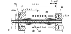
- FIGS. 33A-C The welding method of the conventional thermoplastic resin pipe shown by patent document 2 is demonstrated using FIGS. 33A-C.
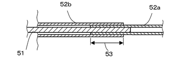
- FIG. 33A a small diameter thermoplastic resin pipe 52a and a large diameter thermoplastic resin pipe 52b are placed on a core material (mandrel) 51 which is a supporting member made of a metal rod such as stainless steel. The tip portions of the two are coaxially stacked to make a stacked portion 53.
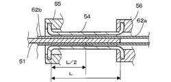
- the overlapping portion 53 which is the portion to be welded, is placed in a pressure tube 54 of good releasability such as a silicon tube whose both ends are held by the left chuck 55 and the right chuck 56.
- a pressure tube 54 of good releasability such as a silicon tube whose both ends are held by the left chuck 55 and the right chuck 56.
- the right chuck portion 56 is moved in the arrow direction on the right side of the drawing to extend the pressure tube 54 in the axial direction.
- the pressure tube 54 extends in the axial direction, it narrows in the radial direction, that is, in the direction perpendicular to the axis of the core material 51, and the inner wall of the pressure tube 54 presses the overlapping portion 53 from the entire circumference.
- the heat source 57 provided around the pressurizing tube 54 is heated, and the heat from the outside is used to melt and heat weld the overlapping portion 53.
- the right chuck 56 is returned to the left side in the drawing, and the pressure tube 54 is returned to the original shape so that the welded thermoplastic resin pipe is taken out.
- thermoplastic resin tube (1) it is possible to uniformly press the overlapping portion of the thermoplastic resin tube. (2) By moving one of the chucks, the compression force of the pressure tube can be changed, and the thermoplastic resin tube can be easily set or removed. (3) The pressure tube can be used repeatedly.
- this conventional method leaves several problems as a method for welding thermoplastic resin pipes or a welding apparatus, including that thermoplastic resin pipes having different thicknesses are stacked and welded.
- thermoplastic resin tubes 62a and 62b try to stay at the original position due to the frictional force with the core material 51, but the inner wall of the pressure tube 54 moves in the direction to separate the butt surfaces.
- a space 63 is created.
- a pinhole is easily generated in the welded portion.
- thermoplastic resin tubes already in a tubular shape are welded and joined, for example, a sheet-like thermoplastic resin material is wound around a core material, butt-welded and thermoplastic resin tubes are formed. It has not been considered to obtain or to weld flat plate-like thermoplastic resin materials in a flat plate shape or to stack and weld in a flat plate shape.
- thermoplastic resin material in a welding apparatus and a welding method for butt welding or overlapping welding of a thermoplastic resin material, (a) generation of pinholes in a welded portion is prevented, and the welding surface is made smooth. (B) The pressure for pressing the portion to be welded is arbitrarily set. (C) It is an object of the present invention to provide a method and an apparatus for welding thermoplastic resin materials which solve various problems of rapidly cooling compression means such as a pressure tube after welding. And the object is to enable (d) internal heating suitable for a combination having a low melting point of the outer tube. Another object of the present invention is to make it possible to replace the pressing unit of the welding device so that welding work of thermoplastic resin materials having different dimensions and the like can be performed with one welding device (e).
- the thermoplastic resin material welding apparatus is a thermoplastic resin material welding apparatus for welding in a state in which the thermoplastic resin material is in close contact with the support member, and the thermoplastic resin material welding
- the pressing means has a pressing means for pressing the target portion and the surface in the vicinity thereof, and a heating means, and the pressing means presses the surface of the welding target portion of the thermoplastic resin material with a predetermined pressure, and then pressing the pressing area
- the compression is continued and the compression area is expanded without changing the relative position of the means and the surface of the portion to be welded of the thermoplastic resin material, and the portion to be welded of the thermoplastic resin material is heated and welded by the heating means,
- the pressure of the compression means is lowered to stop the compression of the thermoplastic resin material, and the welded thermoplastic resin material can be taken out.
- the thermoplastic resin material welding apparatus is a thermoplastic resin material welding apparatus for welding in a state where the thermoplastic resin material is in close contact with the support member, and the thermoplastic resin material welding
- the pressing means has a pressing means for pressing the target part and the surface in the vicinity thereof, and a heating means, and the pressing means presses the surface of the welding target part of the thermoplastic resin material with a first pressure, and then the pressing area While changing the relative position of the pressing means and the surface of the portion to be welded of the thermoplastic resin material with a second pressure larger than the first pressure, the pressing area is expanded and the heating means makes the thermoplastic resin material
- the portion to be welded is heated and welded, and after completion of welding, the pressure of the compression means is lowered to stop the compression of the thermoplastic resin material, and the welded thermoplastic resin
- the surface of the thermoplastic resin material to be welded is pressed with the first pressure, and the thermoplastic resin material to be welded is pressed, and then the pressing means of the pressing area and the thermoplastic resin
- the pressing means of the pressing area and the thermoplastic resin By pressing with a second pressure larger than the first pressure without changing the relative position of the resin material to the surface of the welding target portion, the welding target portion of the thermoplastic resin material and the vicinity thereof are pressed and welded There is.
- thermoplastic resin material welding apparatus is characterized in that the pressure applied to the surface of the thermoplastic resin material to be welded by the pressing means is from a first pressure to a second pressure higher than the first pressure.
- the pressure is continuously increased to expand the compression area. Therefore, an operation to continuously expand the compression area is performed, and the welding target portion of the thermoplastic resin material and the vicinity thereof are continuously ironed to expel air including minute ones, and generation of pinholes in the welding portion To solve the problem (a) by preventing the welding surface and finishing the welding surface smoothly.
- the thermoplastic resin material welding apparatus is a thermoplastic resin material welding apparatus for welding in a state in which the thermoplastic resin material is in close contact with the core material as the support member, and the thermoplastic resin material welding apparatus A pressing means for pressing the welding target portion of the resin material and the surface in the vicinity thereof in a direction perpendicular to the axis of the core material, and a heating means, the pressing means pressing the surface of the welding target portion of the thermoplastic resin material
- the compression is continued with the relative position between the compression means of the compression area and the surface of the portion to be welded of the thermoplastic resin material to be compressed to expand the compression area in the axial direction of the core material.
- a portion to be welded of the thermoplastic resin material is heated and welded by heating means, and after completion of welding, the pressure of the compression means is lowered to stop the compression of the thermoplastic resin material, and the welded thermoplastic resin material can be taken out
- thermoplastic resin material welding apparatus is a thermoplastic resin material welding apparatus for welding in a state in which the thermoplastic resin material is in close contact with the core material as the support member, and the thermoplastic resin material welding apparatus A pressing means for pressing the welding target portion of the resin material and the surface in the vicinity thereof in a direction perpendicular to the axis of the core material, and a heating means, the pressing means pressing the surface of the welding target portion of the thermoplastic resin material Squeeze with a first pressure and then squeeze with a second pressure greater than the first pressure without changing the relative position between the compression means of the compression region and the surface of the thermoplastic resin material to be welded The region is expanded in the axial direction of the core, and the welding target portion of the thermoplastic resin material is heated and welded by the heating means, and the pressure of the
- the surface of the thermoplastic resin material to be welded is pressed with the first pressure, and the thermoplastic resin material to be welded is pressed, and then the pressing means of the pressing area and the thermoplastic resin
- the pressing means of the pressing area and the thermoplastic resin By pressing with a second pressure larger than the first pressure without changing the relative position of the resin material to the surface of the welding target portion, the welding target portion of the thermoplastic resin material and the vicinity thereof are pressed and welded There is.
- the operation of expanding the compression area without changing the relative position between the compression means of the compression area and the surface of the target portion of the thermoplastic resin material to be welded adheres the welding while keeping the abutment surface of the thermoplastic resin material apart.
- the target part and its vicinity will be culled. Air is finely expelled from the gap between the compression means and the thermoplastic resin material and the space between the core material and the thermoplastic resin material, and the core material
- the thermoplastic resin material placed on the core material adheres closely.
- the pressure to be applied to the surface of the thermoplastic resin material welding target portion by the pressing means is greater than the first pressure and the first pressure.
- the pressure is increased continuously to the second pressure to expand the compression region in the axial direction of the core material. Therefore, an operation to continuously expand the compression area is performed, and the welding target portion of the thermoplastic resin material and the vicinity thereof are continuously ironed to expel air including minute ones, and generation of pinholes in the welding portion To solve the problem (a) by preventing the welding surface and finishing the welding surface smoothly.
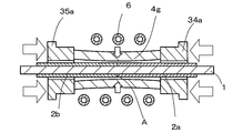
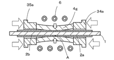
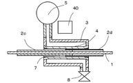
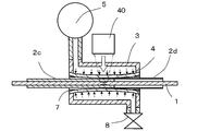
- the pressing means includes a pressure tube which can extend and contract in a direction perpendicular to the axis of the core material, and an axial direction of the core material of the pressure tube.
- a hollow housing having a hollow space having a hollow space forming a cavity between the pressure means and the circumferential surface of the pressure tube, and a fluid supplying the fluid with the fluid.
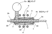
- the hollow housing is partially in intimate contact with the pressurizing tube, and a cavity is formed between the pressurizing tube and the peripheral surface of the pressurizing tube, and the cavity is pressurized by supplying the fluid to the cavity by the fluid supplying means.
- the tube is deformed in a direction perpendicular to the axis of the core material to press the surface of the thermoplastic resin material.
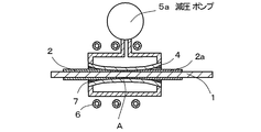
- the pressing means includes a stretchable pressure sheet and a pressure means for applying a fluid pressure to the pressure sheet.
- the pressurizing means is constituted by a hollow housing having an open hole forming a cavity with the pressurizing sheet, and a fluid supplying means for supplying a fluid to the cavity, and the hollow housing is partially in contact with the pressurizing sheet.
- a cavity is formed between the pressure sheet and the pressure sheet, and fluid pressure is supplied to the cavity by a fluid supply means to deform the pressure sheet and press the surface of the thermoplastic resin material.
- the thermoplastic resin material welding apparatus supplies the pressure of the compression means with a gas pressure. More specifically, the gas pressure is increased by a pump, set to a first pressure by a valve, then set to a second pressure, and after welding, the heated gas is discharged from the valve, The pressurized tube is cooled by flowing an unheated gas. As the gas, in addition to air, an inert gas such as nitrogen is used if necessary. By this, the pressure which squeezes a welding object part is made variable arbitrarily, and the said subject (b) is solved. Moreover, the said subject (c) of cooling rapidly compression means, such as a pressurization tube, is solved.
- the pressure of the compression means is supplied by the liquid pressure.
- the liquid in addition to oil, water or the like is used if necessary.
- the pressure which compresses a welding object part is arbitrarily changed, and the said subject (b) is solved.
- the said subject (c) of cooling rapidly compression means such as a pressurization tube, is solved.
- the pressing means includes a pressure tube which can expand and contract in the axial direction of the core material and the direction perpendicular to the axis, and the pressure tube. And pressing means for applying pressure in the axial direction of the material, and applying pressure in the axial direction of the core material to the pressing tube by the pressing means, the pressure tube in a direction perpendicular to the axis of the core material It is configured to be deformed and to press the surface of the thermoplastic resin material.
- the surface of the thermoplastic resin material can be compressed by deforming in the direction perpendicular to the axis of the core material.
- the purpose of the present invention can be achieved by mechanically applying pressure in the axial direction of the pressure tube.
- the thickness of the pressure tube is thick at the end and thinner in the axial direction of the core so as to be thinner toward the center. It is thick.
- the inner diameter of the portion where the thickness of the pressure tube is thin expands and contracts from the portion where the thickness is thick, so the problem (b) of arbitrarily varying the pressure for pressing the portion to be welded is solved.
- the inside diameter of the pressure tube is large at the end, and the center
- the inner diameter of the core material varies in the axial direction so as to be smaller toward the part.
- the pressure for pressing the portion to be welded is arbitrarily varied to solve the problem (b).
- the outer diameter of the pressure tube when the pressure tube is positioned inside the thermoplastic resin material, the outer diameter of the pressure tube is smaller at the end, The outer diameter of the core material varies in the axial direction so as to increase toward the central portion.
- the pressure for pressing the portion to be welded is arbitrarily varied to solve the problem (b).
- the inner diameter or the outer diameter of the pressure tube is made different in the axial direction as described in claim 13 and claim 14 and pressure is applied.
- the thickness of the tube before pressing is made uniform in the axial direction of the core material.
- the pressure which compresses a welding object part is arbitrarily changed, and the said subject (b) is solved.
- the inner diameter of the pressure tube is set to The inner diameter is different in the axial direction so as to be larger at the end and smaller toward the central portion, and the outer diameter of the pressure tube before pressurization is uniform (the same) in the axial direction of the core.
- thermoplastic resin material welding apparatus when the pressure tube is positioned inside the thermoplastic resin material, the outer diameter of the pressure tube is The outside diameter of the core material is different in the axial direction of the core so as to be smaller at the end and larger toward the center, and the inside diameter of the pressure tube before pressurization is uniform (the same) in the axial direction.
- the heating means is provided outside the pressing means. As a result, the heating unit of the thermoplastic resin material is made compact (small).
- thermoplastic resin material welding apparatus In the thermoplastic resin material welding apparatus according to claim 19 of the present invention, a pipe-like core material is used as the core material, and the heating means is disposed in the hollow portion inside the tubular core material. The core material is heated by the heating means, and the heat of the heated core material is transferred to the thermoplastic resin material for welding. By this, internal heating suitable for a combination having a low melting point of the outer tube is realized to solve the problem (d).
- thermoplastic resin material welding apparatus uses the heating means as the high frequency induction heating means, heats the core material by the heating means, and heats the heat of the core material as the thermoplastic resin material It is said that it is welded.
- internal heating suitable for a combination having a low melting point of the outer tube is realized to solve the problem (d).
- the apparatus for welding thermoplastic resin materials according to claim 21 of the present invention uses the heating means as the laser heating means to heat the core material by the heating means, and heats the heat of the heated core material to the thermoplastic resin material. It is told and welded. By this, internal heating suitable for a combination having a low melting point of the outer tube is realized to solve the problem (d).
- thermoplastic resin material welding method the thermoplastic resin material is welded in a state where the surface of the thermoplastic resin material brought into close contact with the support member is compressed with the support member by the compression means.
- a method of welding a resin material wherein a pressing means presses the surface of a portion to be welded of the thermoplastic resin material with a predetermined pressure, and thereafter the pressing means of the pressing area and the surface of the portion to be welded of the thermoplastic resin material Continue to expand the compression area without changing the relative position of the sheet, and heat and weld the welding target portion of the thermoplastic resin material by the heating means, and after completion of the welding, reduce the pressure of the compression means to thermoplasticity The pressure on the resin material is stopped, and the welded thermoplastic resin material is taken out.
- thermoplastic resin material welding method according to claim 23 of the present invention, the thermoplastic resin material is welded in a state where the surface of the thermoplastic resin material brought into close contact with the support member is compressed by the compression means with the support member.
- a method of welding a resin material wherein the surface of the welding target portion of the thermoplastic resin material is pressed with a first pressure by the pressing means, and thereafter the pressing means of the pressing area and the surface of the welding target portion of the thermoplastic resin material While changing the relative position with the second pressure, the second pressure greater than the first pressure squeezes to widen the squeeze area, and the heating target heats and welds the welding target portion of the thermoplastic resin material.
- the pressure of the compression means is lowered to stop the compression of the thermoplastic resin material, and the welded thermoplastic resin material is taken out.
- thermoplastic resin material welding method the thermoplastic resin material welded in a state in which the surface of the thermoplastic resin material adhered to the core material as the support member is pressed by the pressing means.
- the surface of the thermoplastic resin material to be welded is compressed with a predetermined pressure by the compression means, and then the compression means of the compression region and the surface of the thermoplastic resin material to be welded are relative to each other.
- the compression While changing the position, the compression is continued and the compression region is expanded in the axial direction of the core material, and the welding target portion of the thermoplastic resin material is heated and welded by the heating device, and the pressure of the compression device is It is lowered to stop the pressure of the thermoplastic resin material, and the welded thermoplastic resin material is taken out.
- thermoplastic resin material welding method the thermoplastic resin material is welded in a state in which the surface of the thermoplastic resin material adhered to the core material as the supporting member is pressed by the pressing means.
- the surface of the portion to be welded of the thermoplastic resin material is compressed by the first pressure by the compression means, and then the compression means of the compression region and the surface of the portion to be welded of the thermoplastic resin material are used.
- the second pressure greater than the first pressure is compressed to expand the compression region in the axial direction of the core material, and the heating target heats and welds the welding target portion of the thermoplastic resin material
- the pressure of the compression means is lowered to stop the compression of the thermoplastic resin material, and the welded thermoplastic resin material is taken out.
- a pressing unit for a thermoplastic resin material welding device is for a welding device used for a thermoplastic resin material welding device according to any of claims 4 to 6
- a hollow space is formed between the pressure tube, which can be expanded and contracted in the direction perpendicular to the axis of the core material, and the circumferential surface of the pressure tube, and a pump connection communicating with the hollow space is formed.
- a hollow housing having a hole is formed, and when fluid pressure is applied from the pump connection hole to the pressure tube, the pressure tube is deformed to press the surface of the thermoplastic resin material.
- a pressing unit for a thermoplastic resin material welding device is for a welding device used for a thermoplastic resin material welding device according to any one of claims 1 to 3
- the pressure unit includes: an expandable pressure sheet; and a hollow housing having an open hole forming a cavity between the pressure sheet and a pump connection hole communicating with the open hole. When the fluid pressure is applied to the pressure sheet from the pump connection hole, the pressure sheet is deformed to press the surface of the thermoplastic resin material.
- the pressing unit in which the pressing tube is sealingly fixed to the hollow housing is made detachable. As a result, it is possible to weld various thermoplastic resin materials having different dimensions and the like only by replacing the pressing unit with another pressing unit with one welding device.
- the pressing unit in which the pressing sheet is sealingly fixed to the hollow housing is made removable. As a result, it is possible to weld various thermoplastic resin materials having different dimensions and the like only by replacing the pressing unit with another pressing unit with one welding device.
- the fluid supply means is connected to the heating means for heating the fluid, and the fluid pressure of the heated fluid is used.
- the heated gas or liquid even when the thickness of the tube or sheet to be welded is thick, it is possible to heat from both the inside and the outside of the tube or sheet.
- a heat resistant material such as silicone rubber
- oil or the like heated to 280 ° C. can be used as the heated fluid. This allows instantaneous heating and welding of thick tubes or sheets from both the inside and the outside.
- the pressure control unit performs pressure control and pressure reduction control. By this, the welding surface is finished smoothly and the said subject (a) is solved.
- the present invention is a welding apparatus, welding method, and pressing unit for welding apparatus for butt welding or overlapping welding of thermoplastic resin materials, (a) preventing generation of pinholes in the welding portion and making the welding surface smooth Do. (B) The pressure for pressing the portion to be welded is arbitrarily set. (C) After welding, the pressing means such as the pressure tube is rapidly cooled. (D) Allow internal heating suitable for combinations with low melting point of outer tube. (E) The pressing unit for the welding device can be replaced. It solves the problems of
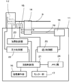
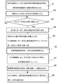
- FIG. 2 is an operation flowchart of the thermoplastic resin welding device according to the first embodiment of the present invention.
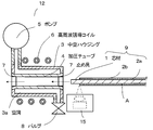
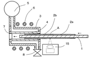
- Sectional drawing which shows the state which inserted the front-end
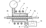
- Sectional drawing which shows the state which positioned the workpiece
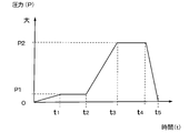
- the graph which showed transition of the pressure of the compression means of the welding apparatus of the thermoplastic resin material concerning 1st embodiment of this invention.
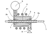
- Sectional drawing which shows the state which applied 1st pressure to the compression means of the heating unit concerning 1st embodiment of this invention, and compressed the abutment surface vicinity of the thermoplastic resin material which is a welding object part.
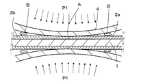
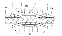
- the partially expanded sectional view which shows the state of butting surface vicinity of the thermoplastic resin material which is the welding object part compressed by 1st pressure by the compression means of the heating unit concerning the 1st embodiment of this invention.
- Sectional drawing which shows the state which gave 2nd pressure to the compression means of the heating unit concerning 1st embodiment of this invention, and expanded the compression area
- the partially expanded sectional view which shows the state of butting surface vicinity of the thermoplastic resin material which was compressed by 2nd pressure by the compression means of the heating unit concerning 1st embodiment of this invention.
- Sectional drawing which shows the state which reduced the pressure of the compression means of the heating unit concerning 1st embodiment of this invention, and stopped compression of a workpiece
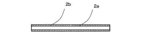
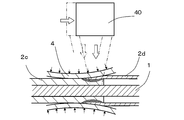
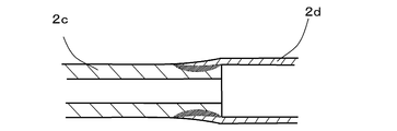
- FIG. 2 is a cross-sectional view of a butt-welded thermoplastic resin material according to the present invention.
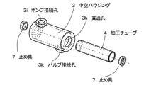
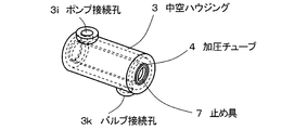
- BRIEF DESCRIPTION OF THE DRAWINGS The perspective view of the press unit for the welding apparatus of the thermoplastic resin material concerning 1st embodiment of this invention.
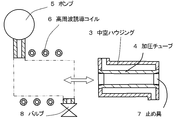
- Sectional drawing which shows the state which removed the press unit of the welding apparatus of the thermoplastic resin material concerning 1st embodiment of this invention from the pump and the valve
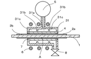
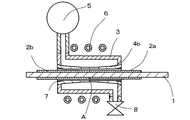
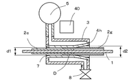
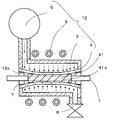
- Sectional drawing which showed the internal structure of the heating unit of the welding apparatus of the thermoplastic resin material concerning 2nd embodiment of this invention, and the positional relationship of a workpiece
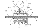
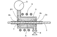
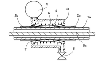
- Sectional drawing which shows the state which began to give pressure to the compression means of the heating unit concerning 2nd embodiment of this invention.
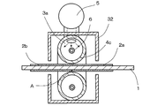
- Sectional drawing which showed the internal structure of the heating unit of the welding apparatus of the thermoplastic resin material concerning 3rd embodiment of this invention, and the positional relationship of a workpiece
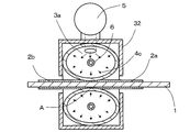
- Sectional drawing which shows the state which applied the pressure to the compression means of the heating unit concerning 3rd embodiment of this invention.
- Sectional drawing which shows the state which applied the pressure to the compression means of the heating unit concerning 4th embodiment of this invention.
- Sectional drawing which shows the state which applied the pressure to the compression means of the heating unit of the welding apparatus of the thermoplastic resin material concerning 5th embodiment of this invention.
- Sectional drawing which showed the internal structure of the heating unit of the welding apparatus of the thermoplastic resin material concerning 6th embodiment of this invention, and the positional relationship of a workpiece
- Sectional drawing which shows the state pressed from the axial direction both sides of the pressure tube of the welding apparatus of the thermoplastic resin material concerning 7th embodiment of this invention.
- Sectional drawing which showed the positional relationship of the heating unit of the welding apparatus of the thermoplastic resin material concerning the 8th embodiment of this invention, and a workpiece
- Sectional drawing which shows the state pressed from the axial direction both sides of the pressure tube of the welding apparatus of the thermoplastic resin material concerning 8th Embodiment of this invention.
- Sectional drawing which showed the positional relationship of the heating unit of the welding apparatus of the thermoplastic resin material concerning 9th embodiment of this invention, and a workpiece
- Sectional drawing which shows the state which applied the pressure to the heating unit of the welding apparatus of the thermoplastic resin material concerning 9th embodiment of this invention.
- Sectional drawing which showed the positional relationship of the laser heating unit which is a heating means of the welding apparatus of the thermoplastic resin material concerning 9th embodiment of this invention, and a workpiece
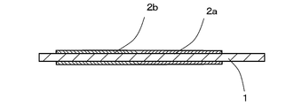
- work welded with the welding apparatus of the thermoplastic resin material concerning 9th embodiment of this invention.
- Sectional drawing which shows the state which applied the pressure to the heating unit of the welding apparatus of the thermoplastic resin material concerning 10th embodiment of this invention.
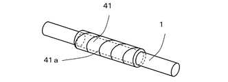
- the core material and the figure of the thermoplastic resin material helically covered on the core material concerning the 11th embodiment of this invention.
- Sectional drawing which shows the state which is applying the pressure to the heating unit of the welding apparatus of the thermoplastic resin material concerning 11th embodiment of this invention.
- Sectional drawing which shows the state which is applying the pressure to the heating unit of the welding apparatus of the thermoplastic resin material concerning 12th embodiment of this invention.
- Sectional drawing which showed the positional relationship of the heating unit of the welding apparatus of the thermoplastic resin material concerning 13th embodiment of this invention, and a workpiece
- Sectional drawing which shows the state which applied the pressure to the heating unit of the welding apparatus of the thermoplastic resin material concerning 13th embodiment of this invention.
- Sectional drawing which showed the positional relationship of the heating unit of the welding apparatus of the thermoplastic resin material concerning 14th embodiment of this invention, and a workpiece
- Sectional drawing which shows the state which applied the pressure to the heating unit of the welding apparatus of the thermoplastic resin material concerning 14th embodiment of this invention.
- FIG. 21 is a cross-sectional view showing a positional relationship between a heating unit and a work of a thermoplastic resin welding device according to a sixteenth embodiment of the present invention.
- FIG. 21 is a cross-sectional view showing a state in which the pressure of the heating unit of the thermoplastic resin welding device according to the sixteenth embodiment of the present invention is reduced.
- FIG. 32 is a cross-sectional view showing a state in which the pressure of the heating unit of the thermoplastic resin welding device according to the sixteenth embodiment of the present invention is returned to before pressure reduction.
- Sectional drawing which shows the state which accumulated the small diameter thermoplastic resin pipe
- Sectional drawing which shows the state which put the welding target part of the thermoplastic resin pipe in the pressure tube with the welding apparatus of the conventional thermoplastic resin pipe.
- Sectional drawing which shows the state which extended
- Sectional drawing which shows the state which abutted the end surface of a pair of thermoplastic resin tubes with an equal diameter on the conventional core material.
- Sectional drawing which shows the state which put the welding target part of the thermoplastic resin pipe in the pressure tube with the welding apparatus of the conventional thermoplastic resin pipe.
- Sectional drawing which shows the state which extended
- FIG. 1 is an external perspective view of a thermoplastic resin welding device 10 according to a first embodiment of the present invention.
- the heating unit 12 and the position sensor 15 are disposed on the upper surface of the main body 11, and the mounting table 14 is movably disposed on a guide rail 13 provided on the upper surface of the main body 11.
- the mounting table 14 includes a movable table 14a, a V-groove 14b, and a clamp member 14c, and heats one end of the workpiece 9 in a state where the workpiece 9 is held by the clamp member 14c in the V-groove 14b formed on the upper surface of the movable table 14a. It can be freely inserted into and removed from the hole 12 a of the unit 12.
- the work 9 is obtained by covering tubular thermoplastic resin materials 2 a and 2 b on a core material (mandrel) 1 which is a support member to be described later. Further, the welding operation unit 16 is disposed in front of the main body portion 11, and the monitor portion 17 is provided at the back side of the main body portion 11. The monitor unit 17 displays operation conditions, operation states, and the like.
- FIG. 2 the schematic block diagram of the welding apparatus 10 of the thermoplastic resin material concerning 1st embodiment of this invention is shown.
- the heating unit 12, the position sensor 15, and the mounting table 14 are disposed on the upper surface of the main body 11, and the welding operation portion 16 is disposed in front of the main body 11, and the monitor 17 is disposed behind the main body 11. did.
- a drive motor 18 for moving the mounting table 14 and a feed screw 19 are provided in the main body 11. Further, the main body 11 accommodates a feed control unit 20, a welding control unit 21, a pressure control unit 22, a heating control unit 23, and a memory unit 24 for storing welding conditions and the like as control means.
- the welding control unit 21 comprehensively controls the welding operation in accordance with an instruction from the operator using the welding operation unit 16 and the monitor unit 17.
- the welding control unit 21 includes a feed control unit 20, a pressure control unit 22 and a heating control unit 23. As a whole, the desired welding operation is performed.
- the pressure control unit 22 controls the pressure of the compression means provided in the heating unit 12.
- the heating control unit 23 controls heating means such as high frequency induction heating and laser heating.
- FIG. 3 shows the internal configuration of the heating unit 12 of the thermoplastic resin welding device 10 according to the first embodiment of the present invention, the position sensor 15, and the core material 1 with the thermoplastic resin materials 2a and 2b.
- FIG. 6 is a schematic cross-sectional view showing the positional relationship of the workpiece 9. Further, in order to understand the invention, FIG. 4 shows an exploded perspective view of the hollow housing 3, the pressure tube 4 and the stopper 7.
- the heating unit 12 has a through hole 3h formed in a hollow housing 3 made of a nonmetal material such as plastic, for example, and passes through the pressure tube 4 made of a silicone rubber tube or the like through the through hole 3h.
- a ring-shaped stopper 7 having a wedge-like cross section is pushed into both ends of the pressurizing tube 4, and the pressurizing tube 4 is fixed to the through hole 3 h of the hollow housing 3 by the stopper 7.
- the hollow housing 3 has a columnar outer shell whose inside is a hollow (hollow space), and through holes 3h are opened at both end faces of the column. Then, press the pressure tube 4 made of a silicone rubber tube or the like through the through hole 3 h, and press the ring-shaped stopper 7 against the inner peripheral surface of the through hole 3 h by bringing the end outer peripheral surface of the pressure tube 4 into contact.
- the hollow space of the hollow housing 3 is sealed with a pressure tube 4 to form a cavity 3a.
- the pump 5 is attached to one end of the hollow housing 3 via the pump connection hole 3i, and the valve 8 is attached to the other end of the hollow housing 3 via the valve connection hole 3k.
- the hollow housing 3, the pressure tube 4, the pump 5, and the valve 8 seal the gap between each other, and the air is pumped into the sealed cavity 3 a by the pump 5 and held at a predetermined pressure, or the air can be taken in and out freely.
- the hollow housing 3, the pressure tube 4, the pump 5, the stopper 7, and the valve 8 constitute “compression means” in the heating unit 12.
- a heating unit 12 is provided with a high frequency induction coil 6 as heating means disposed outside the hollow housing 3. Since the inner hole of the pressure tube 4 is open at both ends, the work 9 can be taken in and out of the inner hole of the ring-shaped stopper 7 fixed to the hollow housing 3 into the inner hole of the pressure tube 4. it can.
- a position sensor 15 is disposed in the vicinity of the inlet of the pressure tube 4.
- the position sensor 15 measures the amount of movement of the thermoplastic resin members 2a and 2b using an image recognition unit such as a CCD image sensor, detects the butting surface A of the thermoplastic resin members 2a and 2b, and then The amount of movement of the thermoplastic resin materials 2a and 2b is measured.
- the feed control unit 20 detects that the abutting surfaces A of the thermoplastic resin materials 2a and 2b have reached the central position of the pressure tube 4 by the position sensor 15, the feed control unit 20 stops the feed of the mounting table 14 on which the work 9 is mounted. Positioning The pressure control unit 22 feeds air into the cavity 3a by the pump 5, and compresses and grips the butting surface A of the thermoplastic resin materials 2a and 2b and the surface in the vicinity thereof with the inner wall of the expanded pressure tube 4.
- the valve 8 controls the pressure in the cavity 3a, and by closing the valve, the pressure in the cavity 3a is maintained at the first pressure (P1) and the second pressure (P2) higher than the first pressure. Can.
- the air accumulated in the cavity 3a can be discharged to reduce the pressure in the cavity 3a.
- the thermoplastic resin materials 2a and 2b put on the core material 1 are pressed and held by the inner wall of the pressure tube 4, the air in the gap between the core material 1 and the thermoplastic resin materials 2a and 2b is pushed out.
- the pressure control unit 22 performs complicated control combining pressure reduction control as well as pressure control. be able to.
- the high frequency induction coil 6 is wound on the outside of the hollow housing 3 several times. With the core material 1 having the thermoplastic resin materials 2 a and 2 b put in the pressure tube 4, under the control of the heating control unit 23, a high frequency current is applied to the high frequency induction coil 6 using a high frequency power supply (not shown). Energize. Then, the metal core material 1 such as a stainless steel rod generates heat, and the butting surfaces A of the thermoplastic resin materials 2a and 2b covering the core material 1 melt and are welded.
- the number of turns and the thickness of the high frequency induction coil 6 may be set to be optimum in accordance with the required heating condition. In some cases, it may be sufficient to draw one loop with the high frequency induction coil 6.
- the valve 8 After welding, when the valve 8 is opened, the heated and heated air is discharged, and the unheated and low-temperature air flows in the cavity 3a. Thereby, the pressurizing tube 4 and the hollow housing 3 are cooled. Thereafter, when the pump 5 is stopped, the pressure in the cavity 3a decreases. That is, the compression force by the pressure tube 4 disappears, the pressure tube 4 returns to the original shape, and the inner wall of the pressure tube 4 separates from the surface of the thermoplastic resin materials 2a and 2b. As a result, the welded thermoplastic resin materials 2a and 2b can be extracted with a small force.
- thermoplastic resin material As a welding apparatus of a thermoplastic resin material, it showed in FIG. 4 among the hollow housing 3, the pressure tube 4, the pump 5, the stopper 7, and the valve 8 which are the component parts of the "compression means” demonstrated above.
- the components other than the pump 5 and the valve 8 can be replaced as one "pressing unit”. That is, a plurality of types of “pressing units” are prepared in advance for different outer diameter dimensions of thermoplastic resin materials, and the pump 5 and valve 8 of the thermoplastic resin material welding device 10 correspond to the target outer diameter. Replace with "Pressing unit”.
- welding operations can be performed by replacing the pressing units for the same outer diameter size with pressing units of different structures.
- FIG. 5 shows an operation flow diagram of the thermoplastic resin material welding apparatus according to the first embodiment of the present invention.
- the operation flow will be described below.
- drawings corresponding to the operation flow are shown and described with reference to these.
- the operator inserts the pair of tubular thermoplastic resin materials 2a and 2b from both ends of the core material (mandrel) 1 and abuts the end surfaces of the thermoplastic resin materials 2a and 2b (step S1) .
- the thermoplastic resin materials 2a and 2b (workpieces 9) are placed on the V-grooves 14b of the moving table 14a of FIG. 1 which has already been shown, and are held down by the clamp members 14c.
- step S2 Under the control of the feed control unit 20, the movable base 14a is moved toward the hole 12a of the heating unit 12 by the drive motor 18 and the feed screw 19, and the core 1 is formed in the hole 12a of the heating unit 12 as shown in FIG. The one end of is inserted (step S2).
- the feed control unit 20 repeats the determination as to whether or not the abutting surface A has been detected until the position sensor 15 detects the abutting surface A (No in step S3).
- the feed control unit 20 causes the pressure motor to move the abutment surface A to a predetermined position by the drive motor 18 as shown in FIG. It sends to the center position of 4 (step S4).
- the feed control unit 20 stops the drive motor 18 and the pressure control unit 22 drives the pump 5.
- the pressure of the cavity 3a rises, and when t1 is reached on the time axis of FIG. 7, the pressure tube 4 squeezes with the first pressure (P1) and grips the vicinity of the abutment surface A (step S5).
- the pressure tube 4 shrinks in a direction perpendicular to the axis of the core 1, that is, in the radial direction, and the inner wall of the pressure tube 4 presses the thermoplastic resin materials 2a and 2b around the butting surface A.
- the abutting surfaces A of the thermoplastic resin materials 2 a and 2 b are mutually pressed on the core material 1. Therefore, the butting surfaces A of the thermoplastic resin materials 2a and 2b are pressed more firmly, but the relative positions of the pressure tube 4 of the pressing means and the surfaces of the portions to be welded of the thermoplastic resin materials 2a and 2b do not change.
- the abutment surface A is not misaligned.
- the first pressure (P1) is a small pressure, the both ends of the pressure tube 4 remain spaced apart in the direction perpendicular to the axis of the core 1.
- the heating control unit 23 controls the heating power source to start the heating of the core 1 by the high frequency induction coil 6.
- the heat of the core material 1 is transmitted to the thermoplastic resin materials 2a and 2b, and the thermoplastic resin materials 2a and 2b begin to soften (step S6).
- the pressure control unit 22 increases the pressure to the second pressure (P2) (t3 of FIG. 7).
- the compression area is enlarged as shown by the open arrow (C) in FIG. 9A and FIG. 9B. As shown in the enlarged cross-sectional view of FIG.
- the pressing area where the inner wall of the pressing tube 4 presses the surface of the thermoplastic resin materials 2a and 2b is an end face from the center of the pressing tube 4 in the axial direction of the core material 1.
- This movement causes the surface of the thermoplastic resin materials 2a and 2b to "squeeze" from the center to the end face side, so the air between the thermoplastic resin materials 2a and 2b and the pressure tube 4 has a fine size It is pushed out from the both ends of the pressurization tube 4 including the thing. Also, air including fine air is expelled from the gap between the core material 1 and the thermoplastic resin materials 2a and 2b (step S7).
- the heating control unit 23 stops heating (step S8).
- the heating may be started when the pressure rises from the first pressure (P1) to the second pressure (P2), or the pressure becomes the second pressure (P2). You may start heating from. For example, in the time axis of FIG. 7, the heating may be started between t2 and t3, or may be started after t3.
- the pressure control unit 22 opens the valve 8 (t4 in the time axis of FIG. 7) to discharge the air having heat and reduce the pressure.
- the pressure of the compression means decreases (t5 on the time axis in FIG. 7)
- the pressure tube 4 returns to its original shape and separates from the thermoplastic resin materials 2a and 2b.
- the pump 5 sends fresh low-temperature air to the cavity 3a, the pressurizing tube 4 and the hollow housing 3 are rapidly cooled.
- thermoplastic resin materials 2a and 2b are not compressed by the compression means, the thermoplastic resin materials 2a and 2b can be removed together with the core material 1 with a small force.
- FIG. 11A the thermoplastic resin materials 2a and 2b are taken out together with the core material 1 from the mounting table 14 and the core material 1 is removed as shown in FIG. 11B, to obtain a welded thermoplastic resin pipe (step S9). .
- the pair of tubular thermoplastic resin members 2a and 2b are fitted from both ends of the core member 1 and the end faces of the thermoplastic resin members 2a and 2b are butt welded. Even when the plastic resin members 2a and 2b are fitted and the end portions of the thermoplastic resin members 2a and 2b are overlapped, the overlapping portions can be welded similarly.
- the surfaces of the thermoplastic resin materials 2a and 2b are heated while moving from the center to the end face side.
- the “compression means” adjusts the pressure in the internal cavity 3a and presses the thermoplastic resin materials 2a and 2b with the flexible pressure tube 4 (b) optionally pressure to compress the portion to be welded It can be set. Then, after welding, the pressure in the cavity 3a of the "compression means” is removed and new air is introduced, whereby the compression means such as the pressure tube can be rapidly cooled after (c) welding.
- the core material 1 is heated, it is possible to perform internal heating suitable for (d) a combination of the thermoplastic resin materials 2a and 2b having a low melting point. Furthermore, since the hollow housing 3, the pressing tube 4 and the stopper 7 are easily removable from the welding apparatus as the pressing unit, (e) the pressing unit of the welding apparatus can be replaced.
- gas pressure such as inert gas
- liquid pressure such as oil and water.
- it may be a gas or liquid, a gas or liquid at normal temperature, or a gas or liquid heated to a high temperature. If the gas or liquid is previously heated to a high temperature, it can be heated from the inside and the outside of the thermoplastic resin material to be welded, so that a thick thermoplastic resin material can be welded in a short time. Thus, any pressing method may be used if necessary.
- FIG. 12 shows an external perspective view of the stopper 7, the pressure tube 4 and the hollow housing 3 when assembled. If the outer shape of the hollow housing 3 of FIG. 12 is the same, one having a different inner diameter, thickness, and material of the pressure tube 4 can be used as a pressure unit and can be replaced. If the pressing unit is removed from the pump 5 and the valve 8 as shown in FIG. 13 and replaced with another pressing unit, another pressing unit with different dimensions or material welds the other thermoplastic resin material. It can be carried out.
- the valve 8 may be omitted.
- Some of the pumps 5 are of a type in which the fluid is drained and the pressure drops when the operation of the pump is stopped, and the pump 5 alone applies the pressure to the first pressure (P1) and the second pressure (P2). This is because pressure, exhaust, and depressurization can be performed. In this case, only the through hole 3 h and the pump connection hole 3 i are provided in the hollow housing 3, and the valve connection hole 3 k is not provided.
- a structure may be adopted in which the fastener 7 is omitted by bonding or welding in advance.
- a fluid heating / heating means may be provided in front of or behind the pump 5 to heat the fluid to a predetermined temperature and to send the heated fluid by the pump 5.
- FIGS. 14A and 14B show the internal configuration of the heating unit of the thermoplastic resin welding device according to the second embodiment of the present invention and the positional relationship between the workpieces.
- the thermoplastic resin material welding apparatus according to the second embodiment of the present invention is characterized in that a partition 31b for pressure distribution adjustment is provided on the inner wall of the hollow housing 31 of the compression means.
- the same parts as those of the first embodiment are given the same reference numerals, and the description thereof is omitted.
- partition walls 31b are formed on the inner wall of the hollow housing 31 of the compression means, from the inner wall in the radial direction of the core 1, that is, in the direction perpendicular to the axis of the core 1.
- the inside of the hollow housing 31 is divided into three spaces by the partition wall 31b.
- the pump connection hole is provided at the axially central position of the hollow housing 31.
- the central space 31a (hollow) directly connected to the pump 5 is a high pressure air chamber into which the air from the pump 5 blows directly, and the left and right spaces 31c, 31c (hollow) are air from the high pressure air chamber 31a.
- the low pressure air chamber which flows in from the gap between the pressure tube 4 and the outer peripheral surface of the pressure tube 4.
- FIG. 14B shows a state where air pressure has started to be applied to the compression means of the heating unit according to the second embodiment of the present invention.
- the pressing tube 4 presses the periphery of the butting surface A of the thermoplastic resin materials 2a and 2b first, although it is a short time. While pressing and bringing the butting surfaces A of the thermoplastic resin materials 2a and 2b into close contact with each other, an operation of squeezing from the vicinity of the butting surfaces A to the outside is performed.
- the core material 1 and the thermoplastic resin materials 2a and 2b are in close contact with each other at the butting surface A of the thermoplastic resin materials 2a and 2b, which are welding target parts, and in the vicinity thereof. It is removed including.
- the thermoplastic resin materials 2a and 2b can be connected by welding on a smooth surface while suppressing the occurrence of pinholes.
- the same effect as that of the above embodiment can be obtained.
- the inside of the hollow housing 31 is divided into three spaces by two partitions 31b and 31b, but an optional number of partitions 31b may be provided if necessary. It may be divided into any number of spaces.
- FIGS. 15A and 15B show the internal configuration of the heating unit of the thermoplastic resin welding device according to the third embodiment of the present invention and the positional relationship between the workpieces.
- the thermoplastic resin material welding apparatus according to the third embodiment of the present invention is characterized in that the thickness of the pressure tube 4b of the pressing means is increased at both ends and reduced at the central portion.
- the same reference numerals are given to the same parts as those in the embodiment described above, and the description will be omitted.
- the thickness of the pressure tube 4b is increased at both ends and reduced at the central portion.
- the pressure tube 4 b is an elastic tube made of, for example, silicone rubber. Therefore, a thick portion is hard to be deformed, and a thin portion is easily deformed.
- the inner diameter of the thin central portion first shrinks, and the circumference of the butting surface A of the thermoplastic resin materials 2a and 2b is firstly pressed. Then, the pressure tube 4b squeezes the contact surface A of the thermoplastic resin members 2a and 2b from the vicinity of the contact surface A while squeezing the contact surfaces A of the thermoplastic resin materials 2a and 2b into contact with each other. .
- FIG. 15B shows a state in which air pressure is applied to the compression means of the heating unit according to the third embodiment of the present invention.
- the occurrence of pinholes can be suppressed and welding can be performed on a smooth surface to connect the thermoplastic resin material.
- the same effect as that of the above embodiment can be obtained.
- FIGS. 16A and 16B show an internal configuration of a heating unit of a thermoplastic resin welding device according to a fourth embodiment of the present invention and a positional relationship between workpieces.
- the through hole 3 h is opened in the hollow housing 3 (31)
- the pressure tube 4 made of an elastic tube such as silicone rubber is made in the through hole 3 h ( 4b)
- push the ring-shaped stopper 7 with a wedge-shaped cross section at both ends of the pressurizing tube 4 (4b) and use the stopper 7 to insert the pressurizing tube 4 (4b) into the through hole of the hollow housing 3 It is fixed.
- the thermoplastic resin welding device according to the fourth embodiment of the present invention is characterized in that the pressure tube 4c has a donut shape.
- the hole (inner hole) at the center of the donut-shaped pressure tube 4c is narrowed, and the thermoplastic resin materials 2a and 2b pass through the hole.
- the outer periphery of the donut-shaped pressure tube 4c and the left and right side surfaces of FIGS. 16A and 16B are covered by an annular frame 32 which has a rectangular cross section and an inner peripheral surface is opened.
- a frame 32 located outside the donut-shaped pressure tube 4c is a guide frame for regulating the position of the donut-shaped pressure tube 4c.
- FIG. 16B shows a state in which air pressure is further applied to the compression means of the heating unit according to the fourth embodiment of the present invention.
- the compression region of the donut-like pressure tube 4c moves from the butting surface A of the thermoplastic resin materials 2a and 2b in the axial direction of the core material 1 and spreads.
- the donut-shaped pressure tube 4c is regulated by the frame 32 as well as the outer peripheral portion as well as the left and right side surfaces of FIG. 16B.
- FIG. 17 shows a state where air pressure is applied to the pressing means of the heating unit of the thermoplastic resin welding device according to the fifth embodiment of the present invention.
- the thermoplastic resin material welding apparatus according to the fifth embodiment of the present invention is characterized in that the cross section of the donut-like pressure tube 4d is elliptical. Further, in accordance with the shape of the donut-like pressure tube 4d, the frame 33 has a shape in which the left and right side surfaces in FIG.
- valve when pressure is applied to the donut-like pressure tube 4d to expand it, and it is regulated by the frame 33, heating is performed in a state where the compression region is expanded in the axial direction of the core material 1; It is possible to connect the thermoplastic resin material by welding on a smooth surface while suppressing the occurrence.
- description of the valve (valve) was abbreviate
- FIG. 18 shows the internal configuration of the heating unit of the thermoplastic resin welding device according to the sixth embodiment of the present invention and the positional relationship between the workpieces.
- the pressure tube 4e includes the center of the donut-shaped pressure tube of the fourth and fifth embodiments of the present invention described above. It is characterized in that the vicinity of the hole is cut off.
- the pressure tube 4e is formed by cutting the shape in the vicinity of the central hole of the donut-shaped pressure tube, that is, in the form of an arc convex inward.
- the hollow housing 3 is attached in a sealed manner in the through hole, and the pump 5 and the valve 8 are attached to the hollow housing 3 to constitute a compression means.
- the high frequency induction coil 6 is disposed outside the hollow housing 3 to form a heating unit.
- the basic configuration is the same as the first embodiment, but the shape of the pressure tube 4e is different.
- the outer diameter of the pressure tube 4e of FIG. 18 may be made uniform (same) so as to have a semicircular cross section. Further, the outer diameter of the pressure tube 4e of FIG. 18 may be changed unevenly.
- FIG. 19A and 19B The positional relationship of the heating unit of the welding apparatus of the thermoplastic resin material concerning 7th embodiment of this invention and a workpiece
- work is shown to FIG. 19A and 19B.
- the donut-like pressure tube 4 f is mechanically moved by the pressing members 34 and 35 in the axial direction of the core 1. It is characterized in that it is compressed to shrink the diameter of the central hole.
- FIG. 19B shows a state in which pressure in the axial direction of the core material 1 is applied by the pressing members 34 and 35 to the donut-shaped pressure tube 4 f of the thermoplastic resin welding device according to the seventh embodiment of the present invention.
- the donut-like pressure tube 4f is sandwiched and compressed by the pressing members 34 and 35, thereby increasing the pressure of the donut-like pressure tube 4f to reduce the diameter of the central hole, and the butt surfaces of the thermoplastic resin materials 2a and 2b Squeeze A.
- the donut-shaped pressure tube 4f is further compressed to apply pressure, and the pressure region is expanded in the axial direction of the core 1.
- the high-frequency induction coil 6 disposed in the donut-shaped pressure tube 4f By heating, it is possible to weld the thermoplastic resin material by welding on a smooth surface while suppressing the occurrence of pinholes.
- 19A and 19B do not show means for cooling the pressure tube 4f, which is compression means, but after welding, air is blown to the compression means such as the pressure tube 4f to rapidly cool it. .
- thermoplastic resin material welding apparatus is, as shown in FIG. 20A, formed of the pressure tube 4g in the same manner as the thermoplastic resin according to the seventh embodiment of the present invention.
- the center of the hole in the donut-shaped pressure tube 4f of the resin welding device is cut out, and the left and right ends in FIGS. 20A and 20B are attached to the pressing members 34a and 35a, and high frequency induction is performed outside the pressure tube 4g. It is characterized in that the coil 6 is disposed.
- the pressing tube 4g is pressed by the pressing members 34a and 35a, and mechanical pressure is applied to the pressing tube 4g from both sides in the axial direction of the core member 1
- the welding can be performed by pressing the periphery of the abutting surface A of the thermoplastic resin material.
- FIG. 20B shows a state where the pressing tube 4g of the thermoplastic resin welding device according to the eighth embodiment of the present invention is pressed by the pressing members 34a and 35a in the axial direction.
- the heating means is disposed in the immediate vicinity of the surface of the pressure tube 4g. Therefore, if necessary, the heating element is used instead of heating the core 1 with the high frequency induction coil 6. It may be used to heat the outside of the pressure tube 4g.
- a means for cooling the pressure tube 4g which is a compression means is not shown, but after welding, air is blown to the compression means such as the pressure tube 4g to rapidly cool it. .
- the thermoplastic resin material welding apparatus according to the ninth embodiment of the present invention is characterized in that a laser heating unit 40 is used as a heating means.
- a material which transmits laser light is adopted, and the core material 1 can be heated by transmitting the laser light.
- the core material 1 When the surface of the core material 1 is irradiated with laser light while rotating the core material 1, the core material 1 generates heat, and the thermoplastic resin materials 2c and 2d placed on the core material 1 melt and weld.
- thermoplastic resin material 2d on the right side in FIGS. 21A and 21B forms an outer pipe
- the tip of the thermoplastic resin material 2d which is the outer pipe is aligned with the center position of the pressure tube 4.
- FIG. 21B shows a state in which pressure is applied to the pressing means of the thermoplastic resin welding device according to the eighth embodiment of the present invention, and laser light is irradiated by the laser heating unit 40.
- the thermoplastic resin materials 2c and 2d while pressing the thermoplastic resin materials 2c and 2d with the pressure tube 4 to which the pressure is applied as in the first embodiment, at the position corresponding to the tip portion of the thermoplastic resin material 2d Irradiate laser light.
- the core material 1 is heated by laser beam irradiation, and generation of pinholes at the portions to be welded of the thermoplastic resin members 2c and 2d is suppressed, and welding is performed on a smooth surface. 2d can be connected.
- FIG. 22A shows the positional relationship between the laser heating unit and the work of the thermoplastic resin welding device according to the ninth embodiment of the present invention.
- FIG. 22A shows a state in which the laser heating unit 40 is moved in the axial direction. As shown in FIG. 22A, the laser heating unit 40 is moved so as to move the irradiation center of the laser light from the tip end position of the thermoplastic resin material 2d which is the outer pipe to the tip end position of the thermoplastic resin material 2d which is the inner pipe. Move from left to right on 22A. As described above, when the laser heating unit 40 is moved in the axial direction, the range in which the core material 1 is heated is expanded, so welding can be performed with a smoother surface.
- FIG. 22B is a cross-sectional view of a workpiece welded by the thermoplastic resin welding device according to the ninth embodiment of the present invention.
- the thermoplastic resin material 2d which is the outer tube
- the pressure tube 4 squeezes while ironing from the tip of the outer tube to the root side. Therefore, the welded portion can be formed into a shape in which the outer diameter smoothly spreads from the inner pipe surface to the outer pipe surface by eliminating the step of the outer pipe tip.
- the same effect as that of the above embodiment can be obtained.
- 21A to 22B show an example in which the thick thermoplastic resin material 2c and the thin thermoplastic resin material 2d are overlapped and welded, but two thick thermoplastic resin materials 2c, When 2 g is overlapped and welded, as shown in FIG. 23, the diameter of the end portion of the pressure tube 4 h may be made smaller on one side (d 1) and larger on the other side (d 2).
- thermoplastic resin materials having the same outer diameter may be butted and welded.
- the thermoplastic resin material can be connected by welding on a smooth surface while suppressing the generation of pinholes at the welding target portion of the thermoplastic resin material.
- FIG. 24A and FIG. 24B show the positional relationship between the heating unit and the work of the thermoplastic resin welding device according to the tenth embodiment of the present invention.
- a tubular core material is used as the core material 1a, and heating is performed to the hollow portion of the tubular core material 1a. It is characterized in that the means 6a is arranged.
- the thermoplastic resin members 2a and 2b having a large diameter can be supported, and the portion to be welded can be heated and welded in a compressed state.
- FIG. 24B shows a state where pressure is applied between the hollow housing 3 and the pressure tube 4 of the thermoplastic resin welding device according to the tenth embodiment of the present invention by the pump 5.
- the heating means 6a may be a sheathed heater or the like other than the high frequency induction coil.
- the end faces of the tubular thermoplastic resin material in the axial direction are butt-welded or lap-welded.
- the present invention can be applied to the case where helical or plate-like thermoplastic resin materials are spirally wound and butt-welded.
- thermoplastic resin material 41 is spirally wound around the core material 1.
- the thermoplastic resin material 41 is spirally wound with compression means (hollow housing 3 and pressure tube 4, pump 5, stopper 7, valve 8) of the heating unit 12 of the present invention. Squeeze the surface. Pressure is applied to the thermoplastic resin material 41 by the compression means, and the compression region is expanded in the axial direction of the core 1 and heated by the heating means 6.
- the abutting surfaces 41a adjacent to each other in a spiral shape of the thermoplastic resin material 41 can be welded on a smooth surface while suppressing the occurrence of pinholes, whereby a thermoplastic resin tube can be formed.
- thermoplastic resin material 41 spirally wound around the core material 1 may be sequentially fed to the holes 12 a of the heating unit 12 by a fixed size to weld by a fixed size.
- the present invention is directed to a plurality of plate-like thermal materials different in material and color.
- the present invention may be applied to the case where plastic resin materials are arranged adjacent to each other and spirally wound around the core member 1 to weld adjacent butting surfaces.
- thermoplastic resin material 42 is wound around the core 1 so that the end faces 42a parallel to the axial direction are butted.
- the pressing means of the heating unit 12 of the present invention presses the welding target portion where the end face 42a of the thermoplastic resin material 42 is butted and the vicinity thereof.
- thermoplastic resin material 42 The pressure is applied to the thermoplastic resin material 42 by the compression means, and the compression region is expanded in the axial direction of the core material 1 and heated by the heating means 6.
- the butt surface 42a parallel to the axis of the core material 1 of the thermoplastic resin material 42 can be welded on a smooth surface with generation of pinholes suppressed, and a thermoplastic resin material can be produced.
- thermoplastic resin materials 2a, 2b, 2c, 2d, 41, 42 are covered on the outer periphery of the core members 1 and 1a.
- the present invention can be applied to the case where the inside and the outside of the thermoplastic resin material and the core material are reversed. That is, as shown in FIG. 29A, compression means in which the thermoplastic resin materials 2a and 2b are placed inside the cylindrical core material 1b and located inside the thermoplastic resin materials 2a and 2b, specifically, pressure is applied.
- the present invention can be applied to the case where the welding target portions of the thermoplastic resin materials 2a and 2b are pressed against the inner peripheral surface of the core 1b on the outer periphery of the tube 4i and heated and welded by the heating means 6.
- the tubular thermoplastic resin materials 2a and 2b are butted inside the cylindrical core material 1b.
- both end faces of a pressure tube 4i which is in the form of a cylinder smaller in diameter than the core member 1b are closed by the hollow housing 36.
- the centers of the disk-shaped end faces 36a and 36b are connected by a tubular spacer 36c.
- a ring-shaped stopper 7a having a wedge-like cross section whose front and back reverses with the stopper 7 is pushed onto the outer circumferences of both ends of the pressure tube 4i to press the pressure tube 4i to both end faces 36a and 36b of the hollow housing 36. It is fixed.
- a plurality of holes are bored in the circumferential surface.
- one end face 36a is connected to the pump 5 through the pump connection hole, and the other end face 36b is connected to the valve 8 through the valve connection hole.
- a fluid such as air is introduced from the pump 5 through the hole of the spacer 36c into the cavity between the pressure tube 4i and the hollow housing 36. It is made to expand in the direction perpendicular to the axis of core material 1b.
- the heating means 6 is arrange
- the pressing tube 4i squeezes the butting surface A of the thermoplastic resin materials 2a and 2b and the vicinity thereof. Pressure is applied to the thermoplastic resin materials 2a and 2b by the compression means, and the compression region is expanded in the axial direction of the core material 1b, and heating is performed by the heating means 6. By this, it is possible to weld the butting surfaces A of the thermoplastic resin materials 2a and 2b on a smooth surface while suppressing the occurrence of pinholes.
- the fluid such as air is removed by the valve 8, the pressure of the pressure means is lowered, the pressing of the thermoplastic resin materials 2a and 2b by the pressure tube 4i is stopped, and the welded thermoplastic resin materials 2a and 2b are cored
- the core material 1b and the thermoplastic resin materials 2a and 2b are separated by taking out the material 1b together.
- the pressure tube 4i As a cross-sectional shape of the pressure tube 4i, if the outer diameter of the pressure tube 4i is made smaller at the end and made different in the axial direction so as to increase toward the central portion, the pressure tube 4i When the part of the pressure tube 4i expands, the abutment surface A, which is a portion to be welded of the thermoplastic resin materials 2a and 2b, and the vicinity thereof at the central portion of the pressure tube 4i can be compressed first.
- the thickness of the pressure tube 4i may be made uniform in the axial direction, or the inner diameter of the pressure tube 4i may be equalized to have a semicircular cross section.
- the present invention can be applied not only to the butt welding or superposition welding of the above-described tubular thermoplastic resin materials but also to butt welding or superposition welding of plate-like thermoplastic resin materials.
- work to FIG. 30A, FIG. 30B was shown.
- the flat support base 1c corresponds to the cores 1, 1a and 1b of the other embodiments
- the flat pressure sheet 45 is the pressure tubes 4, 4b and 4c.
- the hollow housing 37 having the open hole 37a at the lower side corresponds to the hollow housing 3
- the stopper 7b corresponds to the stopper 7, 7a.
- the other parts are basically similar in structure, and the same parts are denoted by the reference numerals and the description thereof is omitted.
- FIG. 30A the end faces of the plate-like thermoplastic resin materials 2e and 2f are placed on the flat support base 1c in a state where the end faces are abutted.
- Heating means 6 are disposed above and below the thermoplastic resin materials 2e and 2f.
- the compression means is constituted by the hollow housing 37, the pressure sheet 45, the pump 5, the stopper 7b, and the valve 8 in substantially the same manner as the embodiments described above.
- a flat pressure sheet 45 is attached to the lower surface of the hollow housing 37 to seal the open hole 37 a of the hollow housing 37.
- the stopper 7 b has an L-shaped cross section, and is fixed to the hollow housing 37 in a state where the corner around the flat pressure sheet 45 is pressed against the hollow housing 37.
- the pump 5 is attached to the hollow housing 37 through the pump connection hole, and the valve 8 is attached through the valve connection hole.
- the pressure sheet 45 can be expanded downward by putting a fluid such as air toward the open hole 37 a of the hollow housing 37 by the pump 5.
- the pressure is lowered by removing air or the like by the valve 8 so that the pressure sheet 45 is returned to the original shape and separated from the surfaces of the thermoplastic resin materials 2e and 2f.
- the heating means 6 is disposed outside the compression means. In FIG. 30 (a), the heating means 6 is arranged as a high frequency induction coil so as to surround the compression means and the support 1c.
- a fluid such as air is introduced by the pump 5 to expand the pressure sheet 45 downward, and the butting surfaces of the thermoplastic resin materials 2e and 2f and the vicinity thereof are compressed by the pressure sheet 45.
- the pressure is applied in this manner, and in a state where the compression region is expanded, the support base 1c is heated by the heating means 6 to heat the butting surface E of the thermoplastic resin materials 2e and 2f and the vicinity thereof on the support base 1c.
- the fluid such as air is removed by the valve 8, the pressure of the pressure means is reduced, the pressing of the thermoplastic resin materials 2e and 2f by the pressure sheet 45 is stopped, and the welded thermoplastic resin material is removed.
- the pressure of the pressure means is reduced, the pressing of the thermoplastic resin materials 2e and 2f by the pressure sheet 45 is stopped, and the welded thermoplastic resin material is removed.
- the pressure pump is used as the pump 5.
- the present invention is not limited to a pressure reducing pump 5 such as a so-called vacuum pump. May be used. More specifically, as shown in FIGS. 31A and 31B, a plurality of air holes 3b are formed on the outer peripheral surface of the cylindrical hollow housing 3 extending along the core material (mandrel) 1, and the pressure tube 4b is formed on the inner wall. Set up.
- the pressurizing tube 4 b has a cylindrical shape whose diameter is reduced toward the central portion in the axial direction, and both ends thereof are fixed by the stoppers 7 and 7.
- the fasteners 7 and 7 have through holes through which the thermoplastic resin materials 2a and 2b can pass. Further, the stoppers 7, 7 are provided with rubber sealing valves 30, 30 for sealing the through holes. At the time of welding and after welding, the work (core 1, thermoplastic resin materials 2a, 2b) is taken in and out through the sealing valves 30, 30.
- the inside of the hollow housing 3 is sealed by attaching the sealing valves 30, 30 made of rubber to both ends of the hollow housing 3 using the pressure reducing pump 5a, and when air is sucked by the pressure reducing pump 5a,
- the space between the pressure tube 4b and the thermoplastic resin materials 2a and 2b, which are objects to be welded, can be depressurized.
- the surface of thermoplastic resin material 2a, 2b can be pressed centering
- the core material 1 (mandrel) is heated by the high frequency induction coil in a state where the surface of the connecting portion of the thermoplastic resin materials 2a and 2b is pressed by the inner wall surface of the pressure tube 4b, and the surface of the connecting portion is welded smoothly can do.
- gas such as air between the inner wall surface of the pressurizing tube 4b and the surface of the connecting portion is sucked by the decompression pump 5a, the inner wall surface of the pressurizing tube 4b and the surface of the connecting portion of the thermoplastic resin materials 2a and 2b adhere Do.
- the inner diameter of the inner hole of the pressure tube 4b is the thermoplastic resin material
- the inner wall surface of the inner hole of the pressure tube 4b is larger than the outer diameter of 2a and 2b, and the surface of the connecting portion of the thermoplastic resin members 2a and 2b is not in contact with each other, and a gap is formed.
- a gas such as air between the inner wall surface of the pressurizing tube 4b and the surface of the connecting portion is sucked by the decompression pump 5a, the inner wall surface of the pressurizing tube 4b and the surface of the connecting portion are in close contact.
- 31B shows a state in which the inner wall surface of the pressure tube 4b is in close contact with the surface of the connecting portion. In this state, when the high frequency induction coil 6 is energized, the core material 1 generates heat, and the surface of the connection portion can be welded smoothly.
- the pressure reduction by the pressure reduction pump 5a is reduced to a plurality of stages, for example, the first pressure (P1) and then to the second pressure (P2).
- the compression means compresses the surface of the welding target portion (connection portion) of the thermoplastic resin material with the first pressure (P1), and then the compression means of the compression region and the welding of the thermoplastic resin material While changing the relative position with the surface of the target portion, the second pressure (P2), which is larger than the first pressure (P1), squeezes to widen the squeezing area, and the heating target is a welding target portion of the thermoplastic resin material Is heated and welded, and after completion of welding, the compression of the thermoplastic resin material is stopped, and the welded thermoplastic resin material can be used as a thermoplastic resin material welding device configured to be removable.
- the pressure reducing pump is used to suck a gas such as air between the inner wall surface of the pressurizing tube and the surface of the connecting portion.
- a gas such as air on the outer wall surface may be sucked.
- 32A to 32C show the configuration as a sixteenth embodiment of the present invention. That is, in the sixteenth embodiment of the present invention, as shown in FIG. 32A, the outer wall of the pressure tube 4 is outside by suctioning gas such as air in the space outside the pressure tube 4 by the decompression pump 5a. Spread out. Then, as shown in FIG.
- the diameter of the inner wall surface of the pressure tube 4 is made larger than the outer diameter of the connecting portion of the thermoplastic resin materials 2a and 2b, and the core material 1 is covered with the core material 1
- the connection portion of the plastic resin members 2a and 2b is inserted in a noncontact manner. Thereafter, when the suction of the decompression pump 5a is stopped, the pressurizing tube 4 squeezes the outer surface of the connecting portion of the thermoplastic resin materials 2a and 2b with the inner wall surface of the pressurizing tube 4 by its own restoring force. In this state, when the high frequency induction coil 6 is energized, the core material (mandrel) 1 generates heat, so that the surface of the connection portion can be welded smoothly.
- the pressure reduction by the pressure reduction pump 5a is reduced to a plurality of stages, for example, the first pressure (P1), and then the second pressure (P2).
- the compression means compresses the surface of the welding target portion of the thermoplastic resin material with the first pressure, and then the compression means of the compression area and the thermoplasticity While changing the relative position with respect to the surface of the welding target portion of the resin material, the second pressure greater than the first pressure squeezes to widen the compression region, and the heating means heats the welding target portion of the thermoplastic resin material It can be used as a welding apparatus of a thermoplastic resin material which has a configuration in which the pressure of the thermoplastic resin material is stopped after welding and the welded thermoplastic resin material can be taken out.
- the present invention can be applied to a method and apparatus for welding thermoplastic resin materials such as thin thermoplastic resin tubes having a diameter of about 0.2 to 10 mm, such as catheters, and thermoplastic resin pipes having a diameter of more than 10 mm. it can.
- thermoplastic resin materials such as thin thermoplastic resin tubes having a diameter of about 0.2 to 10 mm, such as catheters, and thermoplastic resin pipes having a diameter of more than 10 mm. it can.
- catheters it can be applied to a method and apparatus for welding thermoplastic resin materials in which joints are connected by a smooth outer surface without pinholes, and heating methods such as high frequency induction heating and laser heating Can be selected arbitrarily.
- the present invention is not limited to the above embodiments, and can be applied in a wide range, such as butt welding or lap welding of tubular thermoplastic resin materials, butt welding or lap welding of sheet-like or plate-like thermoplastic resin materials.
- the invention can be applied to the welding of thermoplastic resin materials.
Landscapes
- Engineering & Computer Science (AREA)
- Mechanical Engineering (AREA)
- Physics & Mathematics (AREA)
- Health & Medical Sciences (AREA)
- Thermal Sciences (AREA)
- Electromagnetism (AREA)
- Toxicology (AREA)
- Optics & Photonics (AREA)
- Oral & Maxillofacial Surgery (AREA)
- Lining Or Joining Of Plastics Or The Like (AREA)
Description
しかし、この従来の方法は、太さの違う熱可塑性樹脂管を重ね合わせて溶着する方法であるという点を含め、熱可塑性樹脂管の溶着方法あるいは溶着装置としては、幾つかの課題を残していた。
本発明の請求項2に記載の熱可塑性樹脂材の溶着装置は、熱可塑性樹脂材を支持部材に密着させた状態で溶着する熱可塑性樹脂材の溶着装置であって、熱可塑性樹脂材の溶着対象部分とその近傍の表面を圧迫する圧迫手段と、加熱手段と、を有し、圧迫手段で、熱可塑性樹脂材の溶着対象部分の表面を第一の圧力で圧迫し、その後、圧迫領域の圧迫手段と熱可塑性樹脂材の溶着対象部分の表面との相対位置を変えずに、第一の圧力より大きい第二の圧力で圧迫して圧迫領域を広げるとともに、加熱手段で熱可塑性樹脂材の溶着対象部分を加熱して溶着し、溶着終了後に、圧迫手段の圧力を下げて熱可塑性樹脂材の圧迫を止め、溶着した熱可塑性樹脂材を取り出し可能な構成としている。
そのため、連続的に圧迫領域を拡大する動作が行われ、熱可塑性樹脂材の溶着対象部分とその近傍を連続的にしごき、空気を微細なものを含めて追い出して、溶着部分のピンホールの発生を防ぎ、溶着表面を滑らかに仕上げて前記課題(a)を解決している。
本発明の請求項5に記載の熱可塑性樹脂材の溶着装置は、熱可塑性樹脂材を支持部材である芯材に密着させた状態で溶着する熱可塑性樹脂材の溶着装置であって、熱可塑性樹脂材の溶着対象部分とその近傍の表面を、芯材の軸と直角方向に圧迫する圧迫手段と、加熱手段と、を有し、圧迫手段で、熱可塑性樹脂材の溶着対象部分の表面を第一の圧力で圧迫し、その後、圧迫領域の圧迫手段と熱可塑性樹脂材の溶着対象部分の表面との相対位置を変えずに、第一の圧力より大きい第二の圧力で圧迫して圧迫領域を芯材の軸方向に広げるとともに、加熱手段で熱可塑性樹脂材の溶着対象部分を加熱して溶着し、溶着終了後に、圧迫手段の圧力を下げて熱可塑性樹脂材の圧迫を止め、溶着した熱可塑性樹脂材を取り出し可能な構成としている。
そのため、連続的に圧迫領域を拡大する動作が行われ、熱可塑性樹脂材の溶着対象部分とその近傍を連続的にしごき、空気を微細なものを含めて追い出して、溶着部分のピンホールの発生を防ぎ、溶着表面を滑らかに仕上げて前記課題(a)を解決している。
また、本発明の請求項12に記載の熱可塑性樹脂材の溶着装置は、加圧チューブの肉厚を、端部で厚く、中央部に向かって薄くなるよう、芯材の軸方向に異なる肉厚としている。
また、本発明の請求項13に記載の熱可塑性樹脂材の溶着装置は、加圧チューブを熱可塑性樹脂材の外側に位置させた場合において、加圧チューブの内径を、端部で大きく、中央部に向かって小さくなるよう、芯材の軸方向に異なる内径としている。
また、本発明の請求項14に記載の熱可塑性樹脂材の溶着装置は、加圧チューブを熱可塑性樹脂材の内側に位置させた場合において、加圧チューブの外径を、端部で小さく、中央部に向かって大きくなるよう、芯材の軸方向に異なる外径としている。
また、本発明の請求項15に記載の熱可塑性樹脂材の溶着装置は、請求項13や請求項14のように加圧チューブの内径あるいは外径を軸方向に異なる径にするとともに、加圧チューブの加圧前の肉厚を芯材の軸方向に均一にしている。
また、本発明の請求項16に記載の熱可塑性樹脂材の溶着装置は、請求項13のように、加圧チューブを熱可塑性樹脂材の外側に位置させた場合において、加圧チューブの内径を、端部で大きく、中央部に向かって小さくなるよう、軸方向に異なる内径としているとともに、加圧チューブの加圧前の外径を芯材の軸方向に均一(同じ)にしている。
また、本発明の請求項17に記載の熱可塑性樹脂材の溶着装置は、請求項14のように、加圧チューブを熱可塑性樹脂材の内側に位置させた場合において、加圧チューブの外径を、端部で小さく、中央部に向かって大きくなるよう、芯材の軸方向に異なる外径としているとともに、加圧チューブの加圧前の内径を軸方向に均一(同じ)にしている。
また、本発明の請求項18に記載の熱可塑性樹脂材の溶着装置は、加熱手段を圧迫手段の外側に設けている。このことにより、熱可塑性樹脂材の加熱ユニットをコンパクト(小型)に構成している。
このことにより、外管の融点が低い組み合わせにも適する内部加熱を実現して、前記課題(d)を解決している。
このことにより、外管の融点が低い組み合わせにも適する内部加熱を実現して、前記課題(d)を解決している。
このことにより、外管の融点が低い組み合わせにも適する内部加熱を実現して、前記課題(d)を解決している。
また、本発明の請求項23に記載の熱可塑性樹脂材の溶着方法は、支持部材に密着させた熱可塑性樹脂材の表面を支持部材との間で圧迫手段により圧迫した状態で溶着する熱可塑性樹脂材の溶着方法であって、圧迫手段で、熱可塑性樹脂材の溶着対象部分の表面を第一の圧力で圧迫し、その後、圧迫領域の圧迫手段と熱可塑性樹脂材の溶着対象部分の表面との相対位置を変えずに、第一の圧力より大きい第二の圧力で圧迫して圧迫領域を広げるとともに、加熱手段で熱可塑性樹脂材の溶着対象部分を加熱して溶着し、溶着終了後に、圧迫手段の圧力を下げて熱可塑性樹脂材の圧迫を止め、溶着した熱可塑性樹脂材を取り出すようにしている。
また、本発明の請求項24に記載の熱可塑性樹脂材の溶着方法は、支持部材である芯材に密着させた熱可塑性樹脂材の表面を圧迫手段で圧迫した状態で溶着する熱可塑性樹脂材の溶着方法であって、圧迫手段で、熱可塑性樹脂材の溶着対象部分の表面を所定の圧力で圧迫し、その後、圧迫領域の圧迫手段と熱可塑性樹脂材の溶着対象部分の表面との相対位置を変えずに、圧迫を継続して圧迫領域を芯材の軸方向に広げるとともに、加熱手段で熱可塑性樹脂材の溶着対象部分を加熱して溶着し、溶着終了後に、圧迫手段の圧力を下げて熱可塑性樹脂材の圧迫を止め、溶着した熱可塑性樹脂材を取り出すようにしている。
また、本発明の請求項25に記載の熱可塑性樹脂材の溶着方法は、支持部材である芯材に密着させた熱可塑性樹脂材の表面を圧迫手段で圧迫した状態で溶着する熱可塑性樹脂材の溶着方法であって、圧迫手段で、熱可塑性樹脂材の溶着対象部分の表面を第一の圧力で圧迫し、その後、圧迫領域の圧迫手段と熱可塑性樹脂材の溶着対象部分の表面との相対位置を変えずに、第一の圧力より大きい第二の圧力で圧迫して圧迫領域を芯材の軸方向に広げるとともに、加熱手段で熱可塑性樹脂材の溶着対象部分を加熱して溶着し、溶着終了後に、圧迫手段の圧力を下げて熱可塑性樹脂材の圧迫を止め、溶着した熱可塑性樹脂材を取り出すようにしている。
また、本発明の請求項26に記載の熱可塑性樹脂材の溶着装置用の押圧ユニットは、請求項4から請求項6のいずれかに記載の熱可塑性樹脂材の溶着装置に用いられる溶着装置用の押圧ユニットであって、芯材の軸と直角方向に伸縮可能な加圧チューブと、加圧チューブの周面との間に空洞を形成する中空空間が形成され、中空空間に連通するポンプ接続孔が形成された中空ハウジングと、を有し、ポンプ接続孔から加圧チューブに流体圧を与えられたときに、加圧チューブを変形させて熱可塑性樹脂材の表面を圧迫するものとしている。このことにより、寸法等の違う熱可塑性樹脂材を溶着するときに押圧ユニットを他の押圧ユニットに交換して対応できるようにしている。
また、本発明の請求項29に記載の熱可塑性樹脂材の溶着装置は、中空ハウジングに加圧シートを密閉的に固定した押圧ユニットを着脱自在にしている。このことにより、1台の溶着装置で押圧ユニットを他の押圧ユニットに交換するだけで、寸法等の違う各種の熱可塑性樹脂材を溶着することができる。
このように、加熱した気体あるいは液体を用いたことにより、溶着対象であるチューブやシートの厚みが厚い場合でも、チューブやシートの内側と外側の両方から加熱できる。特に、加圧チューブや加圧シートにシリコンゴムなどの耐熱性材料を用いると、加熱した流体として例えば280℃に加熱した油等を用いることができる。このことにより、厚みの厚いチューブやシートを内側と外側の両方から瞬時に加熱して溶着することができる。
このことにより、溶着表面を滑らかに仕上げて前記課題(a)を解決している。
図1に、本発明の第一の実施の形態にかかる熱可塑性樹脂材の溶着装置10の外観斜視図を示す。溶着装置10は、本体部11の上面に加熱ユニット12と位置センサー15を配置し、本体部11の上面に設けたガイドレール13上で載置台14を移動自在に配置している。載置台14は、移動台14a、V溝14b、クランプ部材14cからなり、移動台14aの上面に形成したV溝14bに、ワーク9をクランプ部材14cで押さえた状態で、ワーク9の一端を加熱ユニット12の孔12aに出し入れ自在にしている。当該ワーク9は、後述する支持部材である芯材(マンドレル)1に管状の熱可塑性樹脂材2a、2bを被せたものである。また、本体部11の手前には溶着操作部16を配置し、本体部11の奥側にはモニター部17を設けている。モニター部17には、操作条件や動作状態等を表示する。
溶着制御部21は、溶着操作部16とモニター部17を用いた操作者からの指示に従って、総合的に溶着作業を制御するもので、送り制御部20、圧力制御部22、加熱制御部23を統括して、所望の溶着作業を実行する。圧力制御部22は、加熱ユニット12内に設けた圧迫手段の圧力を制御する。加熱制御部23は、高周波誘導加熱やレーザ加熱などの加熱手段を制御する。
一方、中空ハウジング3の外側には、高周波誘導コイル6を幾重にも巻いている。加圧チューブ4内に熱可塑性樹脂材2a、2bを被せた芯材1を入れた状態で、加熱制御部23の制御の下、この高周波誘導コイル6に図示しない高周波電源を用いて高周波電流を通電する。そうすると、ステンレス棒等の金属製の芯材1が発熱し、芯材1に被せている熱可塑性樹脂材2a、2bの突合せ面Aが溶融して溶着する。なお、高周波誘導コイル6の巻き数や太さについては、求められる加熱条件に応じて最適になるように設定すればよい。高周波誘導コイル6で一つのループを描いただけで良い場合もある。
まず、最初の作業として、操作者が、芯材(マンドレル)1の両端から一対の管状の熱可塑性樹脂材2a、2bを嵌め、熱可塑性樹脂材2a、2bの端面を突き合わせる(ステップS1)。そして、既に示した図1の移動台14aのV溝14bに熱可塑性樹脂材2a、2b(ワーク9)を載せ、クランプ部材14cで押さえる。送り制御部20の制御により、移動台14aを駆動モータ18と送りネジ19により加熱ユニット12の孔12aに向けて動かし、既に示した図3のように、加熱ユニット12の孔12aに芯材1の片端を挿入していく(ステップS2)。送り制御部20は、位置センサー15が突合せ面Aを感知するまで、当該突合せ面Aを感知したかの判定を繰り返す(ステップS3のNo)。図6Aのように、位置センサー15が突合せ面Aを感知すると(ステップS3のYes)、送り制御部20は図6Bのように、駆動モータ18により、突合せ面Aを所定位置である加圧チューブ4の中央の位置まで送る(ステップS4)。
一定時間が経過し、図7の時間軸でt2を過ぎると、圧力制御部22は、圧力を第二の圧力(P2)まで高くする(図7の時間軸でt3)。そして、図9Aと、図9Bの白抜き矢印(C)で示したように圧迫領域を拡大する。図9Bの拡大断面図で示したように、加圧チューブ4の内壁が熱可塑性樹脂材2a、2bの表面を押している圧迫領域は、芯材1の軸方向に加圧チューブ4の中央から端面側へ移動して広がる。この動きは、熱可塑性樹脂材2a、2bの表面を中央から端面側へ「しごく」動作になるので、熱可塑性樹脂材2a、2bと加圧チューブ4の間にあった空気は、微細な大きさのものも含めて加圧チューブ4の両端から押し出される。また、芯材1と熱可塑性樹脂材2a、2bの隙間からも空気が微細なものを含めて追い出される(ステップS7)。
なお、加熱するタイミングは、圧力が第一の圧力(P1)から第二の圧力(P2)に上昇する段階で加熱を開始しても良いし、圧力が第二の圧力(P2)になってから加熱を開始しても良い。例えば、図7の時間軸でいうと、t2からt3の間で加熱を開始してもよいし、t3を過ぎてから加熱を開始してもよい。
なお、本発明では、図4の斜視図に示したように、止め具7で加圧チューブ4を中空ハウジング3の貫通孔3hに固定したものをポンプ5とバルブ8に接続している。図12に、止め具7、加圧チューブ4、中空ハウジング3を組み立てたときの外観斜視図を示す。図12の中空ハウジング3の外形が同じであれば、加圧チューブ4の内径、肉厚、材質が違うものを、押圧ユニットと称して交換使用することができる。押圧ユニットを、図13で示したようにポンプ5とバルブ8から取り外して、他の押圧ユニットと交換すれば、寸法や材質の違う他の押圧ユニットで、他の熱可塑性樹脂材の溶着作業を行うことができる。
また、ポンプ5の前または後ろに流体加熱・保温手段を設けて、流体を所定温度に加熱し、加熱した流体をポンプ5で送る構造にしても良い。
図14A、図14Bに、本発明の第二の実施の形態にかかる熱可塑性樹脂材の溶着装置の加熱ユニットの内部構成とワークの位置関係を示す。本発明の第二の実施の形態にかかる熱可塑性樹脂材の溶着装置では、圧迫手段の中空ハウジング31の内壁に圧力分布調整用の隔壁31bを設けた点に特徴がある。なお、第一の実施の形態と同じ部分については、同じ符号を付して、説明を省略する。
図15A、図15Bに、本発明の第三の実施の形態にかかる熱可塑性樹脂材の溶着装置の加熱ユニットの内部構成とワークの位置関係を示す。本発明の第三の実施の形態にかかる熱可塑性樹脂材の溶着装置では、圧迫手段の加圧チューブ4bの肉厚を両端側で厚く、中央部で薄くしている点に特徴がある。なお、既に説明した実施の形態と同じ部分については、同じ符号を付して、説明を省略する。
図16A、図16Bに、本発明の第四の実施の形態にかかる熱可塑性樹脂材の溶着装置の加熱ユニットの内部構成とワークの位置関係を示す。
既に説明した本発明の第一から第三の実施の形態では、中空ハウジング3(31)に貫通孔3hをあけ、この貫通孔3hにシリコンゴムなどの弾性体チューブでできた加圧チューブ4(4b)を通し、加圧チューブ4(4b)の両端にくさび状の断面をしたリング状の止め具7を押し込んで、止め具7で加圧チューブ4(4b)を中空ハウジング3の貫通孔に固定している。これに対し、本発明の第四の実施の形態にかかる熱可塑性樹脂材の溶着装置では、加圧チューブ4cをドーナッツ状にした点に特徴がある。
図17に、本発明の第五の実施の形態にかかる熱可塑性樹脂材の溶着装置の加熱ユニットの圧迫手段に空気圧を付与した状態を示す。本発明の第五の実施の形態にかかる熱可塑性樹脂材の溶着装置では、ドーナッツ状加圧チューブ4dの断面を楕円形にした点に特徴がある。また、ドーナッツ状加圧チューブ4dの形状に合わせて、枠33は図17の左右側面が外側に広がった形状をなしている。第四の実施の形態と同じく、ドーナッツ状加圧チューブ4dに圧力を加えて膨張させ、枠33で規制して、圧迫領域を芯材1の軸方向に広げた状態で加熱すると、ピンホールの発生を抑制して滑らかな表面で溶着して、熱可塑性樹脂材を接続することができる。その他の点、作用、効果は第四の実施の形態と同じである。なお、図17でも、説明を簡単にするため、バルブ(弁)の記載を省略した。
図18に、本発明の第六の実施の形態にかかる熱可塑性樹脂材の溶着装置の加熱ユニットの内部構成とワークの位置関係を示す。本発明の第六の実施の形態にかかる熱可塑性樹脂材の溶着装置では、加圧チューブ4eとして、上記で説明した本発明の第四、第五の実施の形態のドーナッツ状加圧チューブの中央の孔近傍を切り取った形とした点に特徴がある。
図19A、図19Bに、本発明の第七の実施の形態にかかる熱可塑性樹脂材の溶着装置の加熱ユニットとワークの位置関係を示す。
図19Aに示したように、本発明の第七の実施の形態にかかる熱可塑性樹脂材の溶着装置は、ドーナッツ状加圧チューブ4fを芯材1の軸方向に押圧部材34、35で機械的に圧縮して、中央の孔の径を収縮するようにした点に特徴がある。
図20A、図20Bに、本発明の第八の実施の形態にかかる熱可塑性樹脂材の溶着装置の加熱ユニットとワークの位置関係を示す。本発明の第八の実施の形態にかかる熱可塑性樹脂材の溶着装置は、図20Aに示したように、加圧チューブ4gの形を、上記本発明の第七の実施の形態にかかる熱可塑性樹脂材の溶着装置のドーナッツ状加圧チューブ4fの中央の孔近傍を切り出した形にして、図20A、図20Bにおける左右両端を押圧部材34a、35aに取り付け、加圧チューブ4gの外側に高周波誘導コイル6を配置した点に特徴がある。本発明の第八の実施の形態によれば、押圧部材34a、35aで加圧チューブ4gを押圧して、加圧チューブ4gに芯材1の軸方向の両側から機械的な圧力を加えることで、熱可塑性樹脂材の突合せ面Aの周囲を圧迫して溶着することができる。
また、図20A、Bでは圧迫手段である加圧チューブ4gを冷却する手段は示していないが、溶着後、空気を加圧チューブ4g等の圧迫手段に吹きつけて急速に冷却するようにしている。
図21A、図21Bに、本発明の第九の実施の形態にかかる熱可塑性樹脂材の溶着装置の加熱ユニットとワークの位置関係を示す。本発明の第九の実施の形態にかかる熱可塑性樹脂材の溶着装置は、加熱手段としてレーザ加熱ユニット40を用いた点に特徴がある。中空ハウジング3、加圧チューブ4、熱可塑性樹脂材2c、2dの材料としてレーザ光を透過するものを採用しており、レーザ光を透過させて芯材1を加熱することができる。芯材1を回転させながら芯材1の表面にレーザ光を照射すると、芯材1が発熱し、芯材1の上に被せた熱可塑性樹脂材2c、2dが溶融して溶着する。
なお、レーザ光を照射して熱可塑性樹脂材を溶着する方法については、出願人は特願2011-512335にて技術内容を詳細に開示している。詳しい内容については、同文献を参照されたい。
以上、加熱手段として高周波誘導加熱手段を用いた場合と、レーザ加熱手段を用いた場合について例示して説明したが、必要により他の加熱手段を用いてもよい。
図24A、図24Bに、本発明の第十の実施の形態にかかる熱可塑性樹脂材の溶着装置の加熱ユニットとワークの位置関係を示す。本発明の第十の実施の形態にかかる熱可塑性樹脂材の溶着装置では、図24Aに示したように、芯材1aとして管状の芯材を用い、管状をした芯材1aの中空部に加熱手段6aを配置した点に特徴がある。本発明は、管状をした芯材1aを用いることにより、径の太い熱可塑性樹脂材2a、2bを支持して、溶着対象部分を圧迫した状態で加熱して溶着することができる。
上記本発明の第一の実施の形態から第十の実施の形態では、管状の熱可塑性樹脂材の軸方向の端面同士を突合せ溶着、あるいは重ね合わせ溶着する場合を説明したが、本発明はシート状または板状の熱可塑性樹脂材を螺旋状に巻いて突合せ溶着する場合に適用することができる。
本発明は板状の熱可塑性樹脂材42を芯材1に巻きつけたときに、軸方向と平行に突き合わせた突き合せ面42aとその近傍を溶着する場合にも適用できる。
本発明の第十二の実施の形態では、図27に示すように、芯材1に熱可塑性樹脂材42を巻いて軸方向と平行な端面42aを突き合わせている。これを、図28のように、本発明の加熱ユニット12の圧迫手段で、熱可塑性樹脂材42の端面42aを突き合せた溶着対象部分とその近傍を圧迫する。熱可塑性樹脂材42に、当該圧迫手段により圧力を加え、圧迫領域を芯材1の軸方向に広げた状態で、加熱手段6により加熱する。このことにより、熱可塑性樹脂材42の芯材1の軸と平行な突合せ面42aをピンホールの発生を抑制して滑らかな表面で溶着して、熱可塑性樹脂材を作ることができる。なお、芯材1に巻いた熱可塑性樹脂材42の長さが長い場合は、加熱ユニット12の孔12aに一定寸法ずつ順送りすることにして、一定寸法ずつ溶着すればよい。このように、第十二の実施の形態においても上記の実施の形態と同様の効果を奏することができる。
上記本発明の第一の実施の形態から第十二の実施の形態では、熱可塑性樹脂材2a、2b、2c、2d、41、42を芯材1、1aの外周に被せた場合を説明したが、本発明は熱可塑性樹脂材と芯材の内と外を逆にした場合にも適用することができる。つまり、図29Aに示すように、熱可塑性樹脂材2a、2bを筒状の芯材1bの内側に入れ、熱可塑性樹脂材2a、2bの内側に位置させた圧迫手段、具体的には加圧チューブ4iの外周で熱可塑性樹脂材2a、2bの溶着対象部分を芯材1bの内周面に圧迫し、加熱手段6により加熱して溶着する場合に適用することができる。
なお、加圧チューブ4iの断面形状としては、加圧チューブ4iの外径を、端部で小さく、中央部に向かって大きくなるように軸方向に異なる外径にしておけば、加圧チューブ4iが膨張したときに、加圧チューブ4iの中央部で熱可塑性樹脂材2a、2bの溶着対象部分である突合せ面Aとその近傍を真っ先に圧迫することができる。加圧チューブ4iの肉厚については軸方向に均一にしておいてもよいし、加圧チューブ4iの内径を等しくして断面半円形状としてもよい。加圧チューブ4iの肉厚に差を設けることにより、熱可塑性樹脂材2a、2bの突合せ面Aとその近傍の表面を圧迫するタイミングと圧力を任意に設定することができる。以上のことから、第十三の実施の形態においても上記の実施の形態と同様の効果を奏することができる。
また、本発明は、上記の管状の熱可塑性樹脂材の突合せ溶着や重ね合せ溶着だけでなく、板状の熱可塑性樹脂材の突合せ溶着や重ね合せ溶着等にも適用することができる。
図30A、図30Bに本発明の第十四の実施の形態の板状の熱可塑性樹脂材2e、2fの溶着装置の加熱ユニットとワークの位置関係を示した。なお、図30A、図30Bでは、平板状の支持台1cが他の実施の形態の芯材1、1a、1bに相当し、同じく平面状の加圧シート45が加圧チューブ4、4b、4c、4d、4e、4f、4gに相当し、下方に開放穴37aを有する中空ハウジング37が中空ハウジング3、31に相当し、止め具7bは止め具7、7aに相当する。その他は、基本的には、類似の構成であり、同じ部分には符号を付して説明を省略する。
圧迫手段は、中空ハウジング37、加圧シート45、ポンプ5、止め具7b、バルブ8により構成されていることは、これまで説明した実施の形態とほぼ同じである。中空ハウジング37の下面には、平面状の加圧シート45を貼付して中空ハウジング37の開放穴37aを密閉している。止め具7bはL字状断面をしており、平面状の加圧シート45の周囲の隅を中空ハウジング37に押し付けた状態で、中空ハウジング37に固定している。
上記本発明の第一の実施の形態から第十四の実施の形態では、ポンプ5に加圧ポンプを用いた場合を説明したが、本発明はポンプに、いわゆる真空ポンプのような減圧ポンプ5を用いた構成としてもよい。
詳しくは、図31A、図31Bに示すように、芯材(マンドレル)1に沿って延びた円筒状の中空ハウジング3の外周面に複数の空気孔3bを形成し、内壁に加圧チューブ4bを設ける。当該加圧チューブ4bは軸方向中央部分に向かって径が縮小した円筒状とし、両端が止め具7、7により固定されている。止め具7、7には熱可塑性樹脂材2a、2bが貫通可能な貫通孔が形成されている。さらに当該止め具7、7には当該貫通孔をシールするゴム製の密閉弁30、30が設けられている。溶着時及び溶着後には、密閉弁30、30を通してワーク(芯材1、熱可塑性樹脂材2a、2b)を出し入れする。
その後、減圧ポンプ5aで加圧チューブ4bの内壁面と接続部分の表面の間の空気等の気体を吸引すると、加圧チューブ4bの内壁面と接続部分の表面が密着する。図31Bは、加圧チューブ4bの内壁面と接続部分の表面が密着した状態を示す。この状態で、高周波誘導コイル6に通電すると、芯材1が発熱し、接続部分の表面を滑らかに溶着することができる。
上記本発明の第十五の実施の形態では、減圧ポンプで加圧チューブの内壁面と接続部分の表面の間の空気等の気体を吸引する場合を説明したが、減圧ポンプで加圧チューブの外壁面の空気等の気体を吸引するようにしてもよい。
図32AからCに、その構成を本発明の第十六の実施の形態として示す。すなわち、本発明の第十六の実施の形態では、図32Aのように、減圧ポンプ5aで加圧チューブ4の外側の空間の空気等の気体を吸引することで加圧チューブ4の外壁を外側に拡げる。そして、図32Bのように、加圧チューブ4の内壁面の径を熱可塑性樹脂材2a、2bの接続部の外径より大きくして、加圧チューブ4の孔に芯材1に被せた熱可塑性樹脂材2a、2bの接続部を非接触で挿入する。その後、減圧ポンプ5aの吸引を止めると、加圧チューブ4は自らの復元力で加圧チューブ4の内壁面で熱可塑性樹脂材2a、2bの接続部の外表面を圧迫する。この状態で、高周波誘導コイル6に通電すると、芯材(マンドレル)1が発熱するので、接続部分の表面を滑らかに溶着することができる。
2a、2b 熱可塑性樹脂材
3 中空ハウジング
3a 空洞
4 加圧チューブ
5 ポンプ
6 高周波誘導コイル
8 バルブ(弁)
9 ワーク
12 加熱ユニット
13 ガイドレール
14 載置台
15 位置センサー
16 溶着操作部
17 モニター部
18 駆動モータ
19 送りネジ
20 送り制御部
21 溶着制御部
22 圧力制御部
23 加熱制御部
40 レーザ加熱ユニット
Claims (31)
- 熱可塑性樹脂材を支持部材に密着させた状態で溶着する熱可塑性樹脂材の溶着装置であって、
前記熱可塑性樹脂材の溶着対象部分とその近傍の表面を圧迫する圧迫手段と、
加熱手段と、を有し、
前記圧迫手段で、前記熱可塑性樹脂材の溶着対象部分の表面を所定の圧力で圧迫し、
その後、圧迫領域の前記圧迫手段と前記熱可塑性樹脂材の溶着対象部分の表面との相対位置を変えずに、圧迫を継続して前記圧迫領域を広げるとともに、前記加熱手段で前記熱可塑性樹脂材の溶着対象部分を加熱して溶着し、
溶着終了後に、前記圧迫手段の圧力を下げて前記熱可塑性樹脂材の圧迫を止め、
溶着した熱可塑性樹脂材を取り出し可能な構成とした熱可塑性樹脂材の溶着装置。 - 熱可塑性樹脂材を支持部材に密着させた状態で溶着する熱可塑性樹脂材の溶着装置であって、
前記熱可塑性樹脂材の溶着対象部分とその近傍の表面を圧迫する圧迫手段と、
加熱手段と、を有し、
前記圧迫手段で、前記熱可塑性樹脂材の溶着対象部分の表面を第一の圧力で圧迫し、
その後、圧迫領域の前記圧迫手段と前記熱可塑性樹脂材の溶着対象部分の表面との相対位置を変えずに、前記第一の圧力より大きい第二の圧力で圧迫して圧迫領域を広げるとともに、前記加熱手段で前記熱可塑性樹脂材の溶着対象部分を加熱して溶着し、
溶着終了後に、前記圧迫手段の圧力を下げて前記熱可塑性樹脂材の圧迫を止め、
溶着した熱可塑性樹脂材を取り出し可能な構成とした熱可塑性樹脂材の溶着装置。 - 前記圧迫手段で前記熱可塑性樹脂材の溶着対象部分の表面に加える圧力を、前記第一の圧力から前記第一の圧力より大きい前記第二の圧力に連続的に圧力を高めて圧迫領域を広げるよう構成した請求項2に記載した熱可塑性樹脂材の溶着装置。
- 熱可塑性樹脂材を支持部材である芯材に密着させた状態で溶着する熱可塑性樹脂材の溶着装置であって、
前記熱可塑性樹脂材の溶着対象部分とその近傍の表面を、前記芯材の軸と直角方向に圧迫する圧迫手段と、
加熱手段と、を有し、
前記圧迫手段で、前記熱可塑性樹脂材の溶着対象部分の表面を所定の圧力で圧迫し、
その後、圧迫領域の前記圧迫手段と前記熱可塑性樹脂材の溶着対象部分の表面との相対位置を変えずに、圧迫を継続して前記圧迫領域を前記芯材の軸方向に広げるとともに、前記加熱手段で前記熱可塑性樹脂材の溶着対象部分を加熱して溶着し、
溶着終了後に、前記圧迫手段の圧力を下げて前記熱可塑性樹脂材の圧迫を止め、
溶着した熱可塑性樹脂材を取り出し可能な構成とした熱可塑性樹脂材の溶着装置。 - 熱可塑性樹脂材を支持部材である芯材に密着させた状態で溶着する熱可塑性樹脂材の溶着装置であって、
前記熱可塑性樹脂材の溶着対象部分とその近傍の表面を、前記芯材の軸と直角方向に圧迫する圧迫手段と、
加熱手段と、を有し、
前記圧迫手段で、前記熱可塑性樹脂材の溶着対象部分の表面を第一の圧力で圧迫し、
その後、圧迫領域の前記圧迫手段と前記熱可塑性樹脂材の溶着対象部分の表面との相対位置を変えずに、前記第一の圧力より大きい第二の圧力で圧迫して圧迫領域を前記芯材の軸方向に広げるとともに、前記加熱手段で前記熱可塑性樹脂材の溶着対象部分を加熱して溶着し、
溶着終了後に、前記圧迫手段の圧力を下げて前記熱可塑性樹脂材の圧迫を止め、
溶着した熱可塑性樹脂材を取り出し可能な構成とした熱可塑性樹脂材の溶着装置。 - 前記圧迫手段で前記熱可塑性樹脂材の溶着対象部分の表面に加える圧力を、前記第一の圧力から前記第一の圧力より大きい前記第二の圧力に連続的に圧力を高めて圧迫領域を前記芯材の軸方向に広げるよう構成した請求項5に記載した熱可塑性樹脂材の溶着装置。
- 前記圧迫手段は、前記芯材の軸と直角方向に伸縮可能な加圧チューブと、
前記加圧チューブの前記芯材の軸方向と直角方向に流体圧を加える加圧手段と、を有し、
前記加圧手段を、前記加圧チューブの周面との間に空洞を形成する中空空間を有する中空ハウジングと、
前記空洞に流体を供給する流体供給手段とで構成し、
前記加圧チューブに前記中空ハウジングを一部密着して、前記加圧チューブの周面との間に空洞を形成し、前記空洞に前記流体供給手段により流体を供給することより、
前記加圧チューブを前記芯材の軸と直角方向に変形させて前記熱可塑性樹脂材の表面を圧迫するようにしたことを特徴とする請求項4から請求項6のいずれかに記載の熱可塑性樹脂材の溶着装置。 - 前記圧迫手段は、伸縮可能な加圧シートと、
当該加圧シートに流体圧を加える加圧手段と、を有し、
前記加圧手段を、前記加圧シートとの間に空洞を形成する開放穴を有する中空ハウジングと、
前記空洞に流体を供給する流体供給手段とで構成し、
前記加圧シートに前記中空ハウジングを一部密着して、前記加圧シートとの間に空洞を形成し、
前記空洞に前記流体供給手段により、流体圧を供給することにより、
前記加圧シートを変形させて前記熱可塑性樹脂材の表面を圧迫するようにしたことを特徴とする請求項1から請求項3のいずれかに記載した熱可塑性樹脂材の溶着装置。 - 前記圧迫手段の圧力を気体圧で供給することとしたことを特徴とする請求項1から請求項8のいずれかに記載した熱可塑性樹脂材の溶着装置。
- 前記圧迫手段の圧力を液体圧で供給することとしたことを特徴とする請求項1から請求項8のいずれかに記載した熱可塑性樹脂材の溶着装置。
- 前記圧迫手段は、前記芯材の軸方向および軸と直角方向に伸縮可能な加圧チューブと、
当該加圧チューブを、前記芯材の軸方向に圧力を加える加圧手段と、を有し、
前記加圧手段により、前記加圧チューブに前記芯材の軸方向の圧力を与えることにより、
前記加圧チューブを前記芯材の軸と直角方向に変形させて前記熱可塑性樹脂材の表面を圧迫するようにしたことを特徴とする請求項4から請求項6のいずれかに記載した熱可塑性樹脂材の溶着装置。 - 前記加圧チューブの肉厚を、端部で厚く、中央部に向かって薄くなるよう、前記芯材の軸方向に異なる肉厚とした請求項4から請求項6のいずれかに記載した熱可塑性樹脂材の溶着装置。
- 前記加圧チューブを前記熱可塑性樹脂材の外側に位置させた場合において、
前記加圧チューブの内径を、端部で大きく、中央部に向かって小さくなるよう、前記芯材の軸方向に異なる内径とした請求項4から請求項6のいずれかに記載した熱可塑性樹脂材の溶着装置。 - 前記加圧チューブを前記熱可塑性樹脂材の内側に位置させた場合において、
前記加圧チューブの外径を、端部で小さく、中央部に向かって大きくなるよう、前記芯材の軸方向に異なる外径とした請求項4から請求項6のいずれかに記載した熱可塑性樹脂材の溶着装置。 - 前記加圧チューブの加圧前の肉厚を前記芯材の軸方向に均一にした請求項13または請求項14に記載した熱可塑性樹脂材の溶着装置。
- 前記加圧チューブの加圧前の外径を前記芯材の軸方向に均一にした請求項13に記載した熱可塑性樹脂材の溶着装置。
- 前記加圧チューブの加圧前の内径を前記芯材の軸方向に均一にした請求項14に記載した熱可塑性樹脂材の溶着装置。
- 前記加熱手段を前記圧迫手段の外側に設けたことを特徴とする請求項1から請求項17のいずれかに記載した熱可塑性樹脂材の溶着装置。
- 前記芯材として管状の芯材を用い、管状をした前記芯材の中空部に前記加熱手段を配置し、
前記加熱手段で前記芯材を加熱して、加熱した前記芯材の熱を前記熱可塑性樹脂材に伝えて溶着するようにしたことを特徴とする請求項4から請求項6のいずれかに記載した熱可塑性樹脂材の溶着装置。 - 前記加熱手段を、高周波誘導加熱手段として、
前記加熱手段で前記芯材を加熱し、加熱した前記芯材の熱を前記熱可塑性樹脂材に伝えて溶着するようにしたことを特徴とする請求項1から請求項19のいずれかに記載した熱可塑性樹脂材の溶着装置。 - 前記加熱手段を、レーザ加熱手段として、
前記加熱手段で前記芯材を加熱し、加熱した前記芯材の熱を前記熱可塑性樹脂材に伝えて溶着するようにしたことを特徴とする請求項1から請求項19のいずれかに記載した熱可塑性樹脂材の溶着装置。 - 支持部材に密着させた熱可塑性樹脂材の表面を前記支持部材との間で圧迫手段により圧迫した状態で溶着する熱可塑性樹脂材の溶着方法であって、
前記圧迫手段で、前記熱可塑性樹脂材の溶着対象部分の表面を所定の圧力で圧迫し、
その後、圧迫領域の前記圧迫手段と前記熱可塑性樹脂材の溶着対象部分の表面との相対位置を変えずに、圧迫を継続して前記圧迫領域を広げるとともに、加熱手段で前記熱可塑性樹脂材の溶着対象部分を加熱して溶着し、
溶着終了後に、前記圧迫手段の圧力を下げて前記熱可塑性樹脂材の圧迫を止め、溶着した熱可塑性樹脂材を取り出すようにした熱可塑性樹脂材の溶着方法。 - 支持部材に密着させた熱可塑性樹脂材の表面を前記支持部材との間で圧迫手段により圧迫した状態で溶着する熱可塑性樹脂材の溶着方法であって、
前記圧迫手段で、前記熱可塑性樹脂材の溶着対象部分の表面を第一の圧力で圧迫し、その後、圧迫領域の前記圧迫手段と前記熱可塑性樹脂材の溶着対象部分の表面との相対位置を変えずに、前記第一の圧力より大きい第二の圧力で圧迫して圧迫領域を広げるとともに、加熱手段で前記熱可塑性樹脂材の溶着対象部分を加熱して溶着し、
溶着終了後に、前記圧迫手段の圧力を下げて前記熱可塑性樹脂材の圧迫を止め、溶着した熱可塑性樹脂材を取り出すようにした熱可塑性樹脂材の溶着方法。 - 支持部材である芯材に密着させた熱可塑性樹脂材の表面を圧迫手段で圧迫した状態で溶着する熱可塑性樹脂材の溶着方法であって、
前記圧迫手段で、前記熱可塑性樹脂材の溶着対象部分の表面を所定の圧力で圧迫し、
その後、圧迫領域の前記圧迫手段と前記熱可塑性樹脂材の溶着対象部分の表面との相対位置を変えずに、圧迫を継続して前記圧迫領域を前記芯材の軸方向に広げるとともに、前記加熱手段で前記熱可塑性樹脂材の溶着対象部分を加熱して溶着し、
溶着終了後に、前記圧迫手段の圧力を下げて前記熱可塑性樹脂材の圧迫を止め、溶着した熱可塑性樹脂材を取り出すようにした熱可塑性樹脂材の溶着方法。 - 支持部材である芯材に密着させた熱可塑性樹脂材の表面を圧迫手段で圧迫した状態で溶着する熱可塑性樹脂材の溶着方法であって、
前記圧迫手段で、前記熱可塑性樹脂材の溶着対象部分の表面を第一の圧力で圧迫し、
その後、圧迫領域の前記圧迫手段と前記熱可塑性樹脂材の溶着対象部分の表面との相対位置を変えずに、前記第一の圧力より大きい第二の圧力で圧迫して圧迫領域を前記芯材の軸方向に広げるとともに、前記加熱手段で前記熱可塑性樹脂材の溶着対象部分を加熱して溶着し、
溶着終了後に、前記圧迫手段の圧力を下げて前記熱可塑性樹脂材の圧迫を止め、溶着した熱可塑性樹脂材を取り出すようにした熱可塑性樹脂材の溶着方法。 - 請求項4から請求項6のいずれかに記載の熱可塑性樹脂材の溶着装置に用いられる溶着装置用の押圧ユニットであって、
前記芯材の軸と直角方向に伸縮可能な加圧チューブと、
前記加圧チューブの周面との間に空洞を形成する中空空間が形成され、前記中空空間に連通するポンプ接続孔が形成された中空ハウジングと、
を有し、
前記ポンプ接続孔から前記加圧チューブに流体圧を与えられたときに、前記加圧チューブを変形させて前記熱可塑性樹脂材の表面を圧迫するものである溶着装置用の押圧ユニット。 - 請求項1から請求項3のいずれかに記載の熱可塑性樹脂材の溶着装置に用いられる溶着装置用の押圧ユニットであって、
伸縮可能な加圧シートと、
前記加圧シートとの間に空洞を形成する開放穴が形成され、前記開放穴に連通するポンプ接続孔が形成された中空ハウジングと、
を有し、
前記ポンプ接続孔から前記加圧シートに流体圧を与えられたときに、前記加圧シートを変形させて前記熱可塑性樹脂材の表面を圧迫するものである溶着装置用の押圧ユニット。 - 芯材の軸と直角方向に伸縮可能な加圧チューブと、当該加圧チューブの周面との間に空洞を形成する中空空間が形成され、当該中空空間に連通するポンプ接続孔が形成された中空ハウジングと、を有し、
前記ポンプ接続孔から前記加圧チューブに流体圧を与えられたときに、当該加圧チューブを変形させて前記熱可塑性樹脂材の表面を圧迫する押圧ユニットを着脱自在にした請求項4から請求項6のいずれかに記載の熱可塑性樹脂材の溶着装置。 - 伸縮可能な加圧シートと、当該加圧シートとの間に空洞を形成する開放穴が形成され、開放穴に連通するポンプ接続孔が形成された中空ハウジングと、を有し、
前記ポンプ接続孔から前記加圧シートに流体圧を与えられたときに、当該加圧シートを膨張させて前記熱可塑性樹脂材の表面を圧迫する押圧ユニットを着脱自在にした請求項1から請求項3のいずれかに記載の熱可塑性樹脂材の溶着装置。 - 前記流体供給手段に流体を加熱する加熱手段を接続して、加熱した流体の流体圧を用いることとした請求項8又は請求項7に記載した熱可塑性樹脂材の溶着装置。
- 前記圧力制御部は、加圧制御と減圧制御を行うようにした請求項1から請求項6のいずれかに記載の熱可塑性樹脂材の溶着装置。
Priority Applications (4)
| Application Number | Priority Date | Filing Date | Title |
|---|---|---|---|
| JP2013510831A JP5344415B1 (ja) | 2012-02-14 | 2013-02-13 | 熱可塑性樹脂材の溶着装置、溶着方法、および溶着装置用の押圧ユニット |
| US14/359,814 US9108362B2 (en) | 2012-02-14 | 2013-02-13 | Welding device and method for welding thermoplastic resin articles, and pressing unit for the welding device |
| EP13749251.8A EP2815870B1 (en) | 2012-02-14 | 2013-02-13 | Device for welding thermoplastic resin material |
| CN201380008659.5A CN104114350B (zh) | 2012-02-14 | 2013-02-13 | 热塑性树脂件的焊接装置、焊接方法及焊接装置用的按压单元 |
Applications Claiming Priority (2)
| Application Number | Priority Date | Filing Date | Title |
|---|---|---|---|
| JP2012-029409 | 2012-02-14 | ||
| JP2012029409 | 2012-02-14 |
Publications (1)
| Publication Number | Publication Date |
|---|---|
| WO2013122083A1 true WO2013122083A1 (ja) | 2013-08-22 |
Family
ID=48984193
Family Applications (1)
| Application Number | Title | Priority Date | Filing Date |
|---|---|---|---|
| PCT/JP2013/053349 Ceased WO2013122083A1 (ja) | 2012-02-14 | 2013-02-13 | 熱可塑性樹脂材の溶着装置、溶着方法、および溶着装置用の押圧ユニット |
Country Status (5)
| Country | Link |
|---|---|
| US (1) | US9108362B2 (ja) |
| EP (1) | EP2815870B1 (ja) |
| JP (1) | JP5344415B1 (ja) |
| CN (1) | CN104114350B (ja) |
| WO (1) | WO2013122083A1 (ja) |
Cited By (4)
| Publication number | Priority date | Publication date | Assignee | Title |
|---|---|---|---|---|
| JP2020533203A (ja) * | 2017-09-14 | 2020-11-19 | フォッカー エアロストラクチャーズ ビー.ブイ. | 伝導型溶着 |
| JP2022523618A (ja) * | 2018-12-20 | 2022-04-26 | コーク・アンド・ファン・エンゲレン・コンポジット・ストラクチャーズ・ベー.フェー. | 成形部品の電磁溶接方法で使用するための工具、及びその工具の製造方法 |
| WO2023013447A1 (ja) * | 2021-08-03 | 2023-02-09 | テルモ株式会社 | カテーテルの製造方法およびカテーテルの製造装置 |
| JP2025510064A (ja) * | 2022-03-22 | 2025-04-14 | トップ キャップ ホールディング ゲーエムベーハー | 缶蓋及び缶蓋の製造方法 |
Families Citing this family (17)
| Publication number | Priority date | Publication date | Assignee | Title |
|---|---|---|---|---|
| KR101406076B1 (ko) * | 2013-01-08 | 2014-06-13 | 한전원자력연료 주식회사 | 핵연료봉의 봉단마개 자동 용접장치 |
| JP6542516B2 (ja) * | 2014-08-28 | 2019-07-10 | 三菱製鋼株式会社 | ゴムブッシュ付きスタビライザバーの製造方法 |
| WO2016094847A1 (en) * | 2014-12-12 | 2016-06-16 | Saint-Gobain Performance Plastics Corporation | Ir tube sealer and methods sealing a tube |
| US9327672B1 (en) * | 2015-03-12 | 2016-05-03 | Ford Global Technologies, Llc | Active bolster with bladder member hot welded to reaction plate |
| JP6742697B2 (ja) * | 2015-06-03 | 2020-08-19 | 三菱重工業株式会社 | 樹脂複合材料の硬化装置、および硬化方法 |
| JP5953483B1 (ja) * | 2015-08-31 | 2016-07-20 | 精電舎電子工業株式会社 | 熱カシメ装置 |
| FR3041280B1 (fr) * | 2015-09-23 | 2018-03-23 | Saipem S.A. | Methode d'assemblage de tubes par soudage laser |
| JP6047693B1 (ja) * | 2016-02-23 | 2016-12-21 | 精電舎電子工業株式会社 | レーザ溶着装置およびレーザ溶着方法 |
| CN109571976A (zh) * | 2017-09-28 | 2019-04-05 | 中国商用飞机有限责任公司 | 用于焊接连续纤维增强的热塑性复合材料构件的方法 |
| EP3718749B1 (en) * | 2017-11-30 | 2023-08-30 | Nagano Automation Co., Ltd. | Melt-bonding device |
| JP6990343B2 (ja) * | 2018-07-16 | 2022-01-12 | アルケマ フランス | 熱可塑性材料の部品を溶着する方法 |
| CN110978534A (zh) * | 2019-11-19 | 2020-04-10 | 云南联塑科技发展有限公司 | 一种管道口部预加热装置 |
| CN111516274B (zh) * | 2020-04-13 | 2022-06-10 | 嘉兴雅博电器有限公司 | 一种塑料储物箱盖内密封圈的嵌装设备 |
| EP4088913A1 (en) * | 2021-05-11 | 2022-11-16 | The Boeing Company | Thermoplastic welding tooling |
| US12558853B2 (en) * | 2022-06-08 | 2026-02-24 | Spirit Aerosystems, Inc. | Semi-conformable pressure application system and method for joining composite parts |
| US20260054031A1 (en) * | 2022-08-30 | 2026-02-26 | Biotronik Ag | Heat shrink tubing-free catheter connections |
| US12539388B2 (en) | 2023-05-10 | 2026-02-03 | Bendit Technologies Ltd. | Lubricious liner in catheter tube |
Citations (7)
| Publication number | Priority date | Publication date | Assignee | Title |
|---|---|---|---|---|
| JPH01110127A (ja) * | 1987-09-23 | 1989-04-26 | Georg Fischer Ag | 熱可塑性材料から成る管状部材の溶接方法および装置 |
| JPH03280968A (ja) | 1990-03-30 | 1991-12-11 | Terumo Corp | バルーンカテーテルの製法 |
| JPH08108477A (ja) | 1994-10-07 | 1996-04-30 | Kanegafuchi Chem Ind Co Ltd | 熱可塑性樹脂管の熱溶着連結方法並びにその方法に用いる熱溶着装置 |
| JPH08238676A (ja) | 1995-03-06 | 1996-09-17 | Kanegafuchi Chem Ind Co Ltd | 熱可塑性樹脂管の溶着方法 |
| JP2003507139A (ja) * | 1999-08-23 | 2003-02-25 | ボストン サイエンティフィック リミテッド | インターロックリブ付き結合領域を有するカテーテル |
| JP2005334542A (ja) * | 2004-05-31 | 2005-12-08 | Piolax Medical Device:Kk | 医療用チューブ及びその接合方法 |
| JP2011512335A (ja) | 2008-02-08 | 2011-04-21 | コルゲート・パーモリブ・カンパニー | 組成物およびデバイス |
Family Cites Families (7)
| Publication number | Priority date | Publication date | Assignee | Title |
|---|---|---|---|---|
| US3873395A (en) * | 1973-03-05 | 1975-03-25 | Monon Trailer Inc | Apparatus for forming laminated wall structures |
| CH676689A5 (ja) * | 1988-08-16 | 1991-02-28 | Fischer Ag Georg | |
| JP2678161B2 (ja) * | 1991-10-30 | 1997-11-17 | 九州電子金属 株式会社 | 半導体ウエーハの真空貼着装置 |
| US20080135170A1 (en) * | 2004-05-21 | 2008-06-12 | Fugui He | Systems and Methods for Laser Bonding Catheter Components |
| EP1815500A2 (en) * | 2004-10-09 | 2007-08-08 | Applied Microengineering Limited | Equipment for wafer bonding |
| US7846813B2 (en) * | 2008-02-04 | 2010-12-07 | Fairchild Semiconductor Corporation | Method and apparatus for bonded substrates |
| FI121300B (fi) * | 2008-02-22 | 2010-09-30 | Raute Oyj | Menetelmä ja laite vanerivalmistuksen liiskauspuristuksen suorittamiseksi |
-
2013
- 2013-02-13 US US14/359,814 patent/US9108362B2/en active Active
- 2013-02-13 CN CN201380008659.5A patent/CN104114350B/zh active Active
- 2013-02-13 WO PCT/JP2013/053349 patent/WO2013122083A1/ja not_active Ceased
- 2013-02-13 JP JP2013510831A patent/JP5344415B1/ja active Active
- 2013-02-13 EP EP13749251.8A patent/EP2815870B1/en active Active
Patent Citations (7)
| Publication number | Priority date | Publication date | Assignee | Title |
|---|---|---|---|---|
| JPH01110127A (ja) * | 1987-09-23 | 1989-04-26 | Georg Fischer Ag | 熱可塑性材料から成る管状部材の溶接方法および装置 |
| JPH03280968A (ja) | 1990-03-30 | 1991-12-11 | Terumo Corp | バルーンカテーテルの製法 |
| JPH08108477A (ja) | 1994-10-07 | 1996-04-30 | Kanegafuchi Chem Ind Co Ltd | 熱可塑性樹脂管の熱溶着連結方法並びにその方法に用いる熱溶着装置 |
| JPH08238676A (ja) | 1995-03-06 | 1996-09-17 | Kanegafuchi Chem Ind Co Ltd | 熱可塑性樹脂管の溶着方法 |
| JP2003507139A (ja) * | 1999-08-23 | 2003-02-25 | ボストン サイエンティフィック リミテッド | インターロックリブ付き結合領域を有するカテーテル |
| JP2005334542A (ja) * | 2004-05-31 | 2005-12-08 | Piolax Medical Device:Kk | 医療用チューブ及びその接合方法 |
| JP2011512335A (ja) | 2008-02-08 | 2011-04-21 | コルゲート・パーモリブ・カンパニー | 組成物およびデバイス |
Non-Patent Citations (1)
| Title |
|---|
| See also references of EP2815870A4 |
Cited By (8)
| Publication number | Priority date | Publication date | Assignee | Title |
|---|---|---|---|---|
| JP2020533203A (ja) * | 2017-09-14 | 2020-11-19 | フォッカー エアロストラクチャーズ ビー.ブイ. | 伝導型溶着 |
| JP7287737B2 (ja) | 2017-09-14 | 2023-06-06 | フォッカー エアロストラクチャーズ ビー.ブイ. | 伝導型溶着 |
| JP2022523618A (ja) * | 2018-12-20 | 2022-04-26 | コーク・アンド・ファン・エンゲレン・コンポジット・ストラクチャーズ・ベー.フェー. | 成形部品の電磁溶接方法で使用するための工具、及びその工具の製造方法 |
| JP7478155B2 (ja) | 2018-12-20 | 2024-05-02 | コーク・アンド・ファン・エンゲレン・コンポジット・ストラクチャーズ・ベー.フェー. | 成形部品の電磁溶接方法で使用するための工具、及びその工具の製造方法 |
| WO2023013447A1 (ja) * | 2021-08-03 | 2023-02-09 | テルモ株式会社 | カテーテルの製造方法およびカテーテルの製造装置 |
| JPWO2023013447A1 (ja) * | 2021-08-03 | 2023-02-09 | ||
| JP7835764B2 (ja) | 2021-08-03 | 2026-03-25 | テルモ株式会社 | カテーテルの製造方法およびカテーテルの製造装置 |
| JP2025510064A (ja) * | 2022-03-22 | 2025-04-14 | トップ キャップ ホールディング ゲーエムベーハー | 缶蓋及び缶蓋の製造方法 |
Also Published As
| Publication number | Publication date |
|---|---|
| US9108362B2 (en) | 2015-08-18 |
| US20140326411A1 (en) | 2014-11-06 |
| JPWO2013122083A1 (ja) | 2015-05-11 |
| EP2815870A4 (en) | 2015-10-28 |
| CN104114350A (zh) | 2014-10-22 |
| EP2815870A1 (en) | 2014-12-24 |
| EP2815870B1 (en) | 2019-09-11 |
| CN104114350B (zh) | 2017-06-13 |
| JP5344415B1 (ja) | 2013-11-20 |
Similar Documents
| Publication | Publication Date | Title |
|---|---|---|
| WO2013122083A1 (ja) | 熱可塑性樹脂材の溶着装置、溶着方法、および溶着装置用の押圧ユニット | |
| WO2023103146A1 (zh) | 具有管道内圆顶紧对位机构的激光焊接设备 | |
| JP5380189B2 (ja) | 熱間バルジ成形装置 | |
| WO2011162345A1 (ja) | 接合方法および接合装置 | |
| JPS6362408B2 (ja) | ||
| CN106715093A (zh) | 热铆装置 | |
| WO2020163694A1 (en) | Ultrasonic sonotrode with workpiece clamping tool | |
| CN103459124A (zh) | 制造用于包装管的管子的设备和方法 | |
| CN221022321U (zh) | 增强复合管的封口设备 | |
| CN106255642A (zh) | 用于包装套筒的热活化的方法和装置 | |
| US20220024145A1 (en) | Infrared welding machine | |
| TW200303968A (en) | A method and a device for connecting a plastic line and a plastic socket | |
| JP5382794B2 (ja) | 熱可塑性樹脂管の回転摩擦接合方法 | |
| US20150156821A1 (en) | Heating element for a plastic-tube butt-welding machine, method for manufacturing a panel-type radiator, and plastic-tube butt-welding machine | |
| RU2260512C2 (ru) | Устройство для неподвижного приваривания круглой сплошной заготовки с использованием ультразвука | |
| JP6739104B2 (ja) | 可撓性チューブと樹脂成形品の超音波振動溶着方法、および超音波振動溶着装置 | |
| KR101553638B1 (ko) | 자동융착기 | |
| JP7067329B2 (ja) | 樹脂成形品の接合方法 | |
| CN117644663A (zh) | 聚乙烯管材热熔连接工艺 | |
| JP5144134B2 (ja) | 接着剤類収容パウチの製造法 | |
| CN107053686B (zh) | 一种中空塑料件表面焊接其他塑料件的加工方法及其实现装置 | |
| JP7050959B2 (ja) | 時間指定の空気袋システムを有する接合組立体システム | |
| JP3364815B2 (ja) | 熱可塑性樹脂管の熱溶着連結方法並びにその方法に用いる熱溶着装置 | |
| JP2002542072A (ja) | チューブ端部を結合するための装置 | |
| KR101211631B1 (ko) | 금속 주름관 제조 방법 및 제조 장치 |
Legal Events
| Date | Code | Title | Description |
|---|---|---|---|
| ENP | Entry into the national phase |
Ref document number: 2013510831 Country of ref document: JP Kind code of ref document: A |
|
| 121 | Ep: the epo has been informed by wipo that ep was designated in this application |
Ref document number: 13749251 Country of ref document: EP Kind code of ref document: A1 |
|
| WWE | Wipo information: entry into national phase |
Ref document number: 14359814 Country of ref document: US |
|
| WWE | Wipo information: entry into national phase |
Ref document number: 2013749251 Country of ref document: EP |
|
| NENP | Non-entry into the national phase |
Ref country code: DE |