WO2013122158A1 - Actionneur linéaire électrique - Google Patents
Actionneur linéaire électrique Download PDFInfo
- Publication number
- WO2013122158A1 WO2013122158A1 PCT/JP2013/053554 JP2013053554W WO2013122158A1 WO 2013122158 A1 WO2013122158 A1 WO 2013122158A1 JP 2013053554 W JP2013053554 W JP 2013053554W WO 2013122158 A1 WO2013122158 A1 WO 2013122158A1
- Authority
- WO
- WIPO (PCT)
- Prior art keywords
- housing
- linear actuator
- electric linear
- retaining ring
- sleeve
- Prior art date
- Legal status (The legal status is an assumption and is not a legal conclusion. Google has not performed a legal analysis and makes no representation as to the accuracy of the status listed.)
- Ceased
Links
Images


Classifications
-
- F—MECHANICAL ENGINEERING; LIGHTING; HEATING; WEAPONS; BLASTING
- F16—ENGINEERING ELEMENTS AND UNITS; GENERAL MEASURES FOR PRODUCING AND MAINTAINING EFFECTIVE FUNCTIONING OF MACHINES OR INSTALLATIONS; THERMAL INSULATION IN GENERAL
- F16H—GEARING
- F16H25/00—Gearings comprising primarily only cams, cam-followers and screw-and-nut mechanisms
- F16H25/18—Gearings comprising primarily only cams, cam-followers and screw-and-nut mechanisms for conveying or interconverting oscillating or reciprocating motions
- F16H25/20—Screw mechanisms
- F16H25/22—Screw mechanisms with balls, rollers, or similar members between the co-operating parts; Elements essential to the use of such members
- F16H25/2204—Screw mechanisms with balls, rollers, or similar members between the co-operating parts; Elements essential to the use of such members with balls
-
- F—MECHANICAL ENGINEERING; LIGHTING; HEATING; WEAPONS; BLASTING
- F16—ENGINEERING ELEMENTS AND UNITS; GENERAL MEASURES FOR PRODUCING AND MAINTAINING EFFECTIVE FUNCTIONING OF MACHINES OR INSTALLATIONS; THERMAL INSULATION IN GENERAL
- F16H—GEARING
- F16H25/00—Gearings comprising primarily only cams, cam-followers and screw-and-nut mechanisms
- F16H25/18—Gearings comprising primarily only cams, cam-followers and screw-and-nut mechanisms for conveying or interconverting oscillating or reciprocating motions
- F16H25/20—Screw mechanisms
- F16H25/24—Elements essential to such mechanisms, e.g. screws, nuts
-
- F—MECHANICAL ENGINEERING; LIGHTING; HEATING; WEAPONS; BLASTING
- F16—ENGINEERING ELEMENTS AND UNITS; GENERAL MEASURES FOR PRODUCING AND MAINTAINING EFFECTIVE FUNCTIONING OF MACHINES OR INSTALLATIONS; THERMAL INSULATION IN GENERAL
- F16H—GEARING
- F16H25/00—Gearings comprising primarily only cams, cam-followers and screw-and-nut mechanisms
- F16H25/18—Gearings comprising primarily only cams, cam-followers and screw-and-nut mechanisms for conveying or interconverting oscillating or reciprocating motions
- F16H25/20—Screw mechanisms
- F16H25/22—Screw mechanisms with balls, rollers, or similar members between the co-operating parts; Elements essential to the use of such members
- F16H25/2204—Screw mechanisms with balls, rollers, or similar members between the co-operating parts; Elements essential to the use of such members with balls
- F16H25/2214—Screw mechanisms with balls, rollers, or similar members between the co-operating parts; Elements essential to the use of such members with balls with elements for guiding the circulating balls
-
- H—ELECTRICITY
- H02—GENERATION; CONVERSION OR DISTRIBUTION OF ELECTRIC POWER
- H02K—DYNAMO-ELECTRIC MACHINES
- H02K7/00—Arrangements for handling mechanical energy structurally associated with dynamo-electric machines, e.g. structural association with mechanical driving motors or auxiliary dynamo-electric machines
- H02K7/06—Means for converting reciprocating motion into rotary motion or vice versa
-
- F—MECHANICAL ENGINEERING; LIGHTING; HEATING; WEAPONS; BLASTING
- F16—ENGINEERING ELEMENTS AND UNITS; GENERAL MEASURES FOR PRODUCING AND MAINTAINING EFFECTIVE FUNCTIONING OF MACHINES OR INSTALLATIONS; THERMAL INSULATION IN GENERAL
- F16B—DEVICES FOR FASTENING OR SECURING CONSTRUCTIONAL ELEMENTS OR MACHINE PARTS TOGETHER, e.g. NAILS, BOLTS, CIRCLIPS, CLAMPS, CLIPS OR WEDGES; JOINTS OR JOINTING
- F16B21/00—Means for preventing relative axial movement of a pin, spigot, shaft or the like and a member surrounding it; Stud-and-socket releasable fastenings
- F16B21/10—Means for preventing relative axial movement of a pin, spigot, shaft or the like and a member surrounding it; Stud-and-socket releasable fastenings by separate parts
- F16B21/16—Means for preventing relative axial movement of a pin, spigot, shaft or the like and a member surrounding it; Stud-and-socket releasable fastenings by separate parts with grooves or notches in the pin or shaft
- F16B21/18—Means for preventing relative axial movement of a pin, spigot, shaft or the like and a member surrounding it; Stud-and-socket releasable fastenings by separate parts with grooves or notches in the pin or shaft with circlips or like resilient retaining devices, i.e. resilient in the plane of the ring or the like; Details
- F16B21/183—Means for preventing relative axial movement of a pin, spigot, shaft or the like and a member surrounding it; Stud-and-socket releasable fastenings by separate parts with grooves or notches in the pin or shaft with circlips or like resilient retaining devices, i.e. resilient in the plane of the ring or the like; Details internal, i.e. with spreading action
-
- F—MECHANICAL ENGINEERING; LIGHTING; HEATING; WEAPONS; BLASTING
- F16—ENGINEERING ELEMENTS AND UNITS; GENERAL MEASURES FOR PRODUCING AND MAINTAINING EFFECTIVE FUNCTIONING OF MACHINES OR INSTALLATIONS; THERMAL INSULATION IN GENERAL
- F16H—GEARING
- F16H25/00—Gearings comprising primarily only cams, cam-followers and screw-and-nut mechanisms
- F16H25/18—Gearings comprising primarily only cams, cam-followers and screw-and-nut mechanisms for conveying or interconverting oscillating or reciprocating motions
- F16H25/20—Screw mechanisms
- F16H2025/2062—Arrangements for driving the actuator
- F16H2025/2081—Parallel arrangement of drive motor to screw axis
-
- Y—GENERAL TAGGING OF NEW TECHNOLOGICAL DEVELOPMENTS; GENERAL TAGGING OF CROSS-SECTIONAL TECHNOLOGIES SPANNING OVER SEVERAL SECTIONS OF THE IPC; TECHNICAL SUBJECTS COVERED BY FORMER USPC CROSS-REFERENCE ART COLLECTIONS [XRACs] AND DIGESTS
- Y10—TECHNICAL SUBJECTS COVERED BY FORMER USPC
- Y10T—TECHNICAL SUBJECTS COVERED BY FORMER US CLASSIFICATION
- Y10T74/00—Machine element or mechanism
- Y10T74/18—Mechanical movements
- Y10T74/18568—Reciprocating or oscillating to or from alternating rotary
- Y10T74/18576—Reciprocating or oscillating to or from alternating rotary including screw and nut
Definitions
- the present invention relates to an electric linear actuator having a ball screw mechanism used in a drive unit of a general industrial electric motor or automobile, and more specifically, a rotational input from an electric motor is applied to a ball in a transmission or a parking brake of the automobile.
- the present invention relates to an electric linear actuator that converts a linear motion of a drive shaft through a screw mechanism.
- a trapezoidal screw or a gear mechanism such as a rack and pinion is generally used as a mechanism for converting the rotational motion of the electric motor into a linear motion in the axial direction. Since these conversion mechanisms involve a sliding contact portion, the power loss is large, and it is necessary to increase the size of the electric motor and increase the power consumption. Therefore, a ball screw mechanism has been adopted as a more efficient actuator.
- a ball screw shaft constituting a ball screw can be driven to rotate by an electric motor supported by a housing, and an output member coupled to a nut by rotating the ball screw shaft. Can be displaced in the axial direction. Since the ball screw mechanism has very low friction and the ball screw shaft easily rotates due to the thrust load acting on the output member side, it is necessary to hold the position of the output member when the electric motor is stopped.
- a brake means is provided in an electric motor, or a low-efficiency thing such as a worm gear is provided as a transmission means.
- an electric motor as shown in FIG. Linear actuators are known.
- the electric linear actuator 50 includes a ball screw shaft 51 that is rotationally driven by an electric motor (not shown), and a ball screw nut 52 that is screwed onto the ball screw shaft 51 via a ball (not shown).
- a ball screw mechanism 53 provided is employed.
- the ball screw shaft 51 is rotatably supported by cylindrical housings 54 and 55 by two rolling bearings 56 and 57. These rolling bearings 56 and 57 are fixed by a locking member 59 for preventing loosening via a fixing lid 58.
- a spiral screw groove 51a is formed on the outer periphery of the ball screw shaft 51, and a cylindrical ball screw nut 52 is screwed through the ball.
- a spiral screw groove 52a is formed on the inner periphery of the ball screw nut 52, and a large diameter portion 60 is formed at the end.
- a flat portion 61 is formed on the side surface of the large-diameter portion 60 and is cut so that the end surface is flat.
- a cam follower (rotation stop means) 62 projects from the substantially central portion of the flat portion 61 toward the outside in the radial direction.
- the present invention has been made in view of such problems of the prior art, and an object of the present invention is to provide an electric linear actuator that reduces sliding friction and wear, and has a simple structure and reduced cost. .
- the invention described in claim 1 of the present invention is a cylindrical housing made of an aluminum light alloy, an electric motor attached to the housing, and the rotational force of the electric motor as a motor shaft. And a ball screw mechanism that converts the rotational motion of the electric motor to a linear motion in the axial direction of the drive shaft via the speed reduction mechanism, and this ball screw mechanism is mounted on the housing.
- a nut that is rotatably supported through the pair of support bearings and is not axially movable, and has a helical thread groove formed on the inner periphery, and is inserted into the nut via a number of balls.
- a screw that is coaxially integrated with the drive shaft has a helical thread groove corresponding to the thread groove of the nut on the outer periphery, and is supported so as to be non-rotatable and axially movable with respect to the housing
- a cylindrical sleeve is fitted into the housing hole of the housing, and an axial direction is formed on the inner periphery of the sleeve.
- a pair of concave grooves are formed at opposite positions and a guide pin implanted at the end of the screw shaft is engaged, and an annular groove is formed in the opening of the housing hole of the housing, The sleeve is prevented from coming off while being pressed by a hole retaining ring mounted in the annular groove.
- a cylindrical housing made of aluminum light alloy, an electric motor attached to the housing, a reduction mechanism that transmits the rotational force of the electric motor through the motor shaft, and electric operation through the reduction mechanism.
- a ball screw mechanism that converts the rotational motion of the motor into a linear motion in the axial direction of the drive shaft.
- the ball screw mechanism is rotatable via a pair of support bearings mounted on the housing and cannot move in the axial direction.
- a cylindrical sleeve is fitted into the housing hole of the housing, extends in the axial direction on the inner periphery of the sleeve, and has a pair of concave grooves formed at opposite positions so as to be planted at the end of the screw shaft.
- An annular groove is formed in the opening of the housing accommodation hole, and the sleeve is prevented from coming off while being pressed by a retaining ring for a hole attached to the annular groove.
- the retaining ring is formed with a curved portion having an apex at least at one position at a position symmetrical with respect to the notch, the retaining ring An axial load is generated by the spring force, a predetermined preload can be applied to the sleeve, and the occurrence of wear, noise, or vibration of the housing can be reliably prevented.
- the retaining ring is formed by press working using a wire rod whose corners are previously rounded, post-processing is not required, and mass productivity is improved.
- the sleeve is formed of a sintered alloy that can be carburized and quenched as in the invention described in claim 6, even if the sleeve has a high workability and a complicated shape, it can be easily and accurately performed. It can be formed into a desired shape and size.
- the housing is formed by aluminum die casting, it is rich in mass productivity and cost reduction can be achieved.
- the guide pin is made of a needle roller for a needle roller bearing
- the wear resistance and shear strength are excellent, and the availability is good and the cost is reduced.
- crowning is formed on the outer peripheral surface, so that edge load is prevented in contact with the groove of the sleeve, reducing the contact surface pressure, and durability over a long period of time. Can be improved.
- An electric linear actuator includes a cylindrical housing made of an aluminum light alloy, an electric motor attached to the housing, a reduction mechanism that transmits the rotational force of the electric motor via a motor shaft, and the reduction gear.
- a ball screw mechanism that converts the rotational motion of the electric motor into a linear motion in the axial direction of the drive shaft via a mechanism, and the ball screw mechanism is rotatable via a pair of support bearings mounted on the housing
- a nut that is supported so as not to move in the axial direction and has a helical thread groove formed on the inner periphery thereof, and is inserted into the nut via a number of balls, and is coaxially integrated with the drive shaft,
- a spiral screw groove corresponding to the screw groove of the nut is formed on the outer periphery, and the screw shaft is configured so as to be non-rotatable and axially movable with respect to the housing.
- a cylindrical sleeve is fitted into the housing hole of the housing, and extends axially and opposes the inner periphery of the sleeve.
- a pair of concave grooves is formed at a position to engage a guide pin implanted at the end of the screw shaft, and an annular groove is formed in the opening of the housing hole of the housing. Since the sleeve is retained by being pressed by the retaining ring for the hole, the sliding friction and wear of the housing are reduced, and an electric linear actuator with a simple structure and low cost is provided. can do.
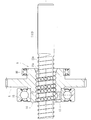
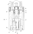
- FIG. 1 is a longitudinal sectional view showing an embodiment of an electric linear actuator according to the present invention. It is a longitudinal cross-sectional view which shows the ball screw mechanism of FIG.
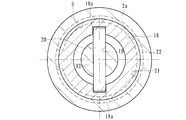
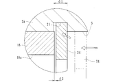
- FIG. 3 is a transverse sectional view taken along line III-III in FIG. It is a principal part enlarged view which shows the mounting part of the retaining ring of FIG.
- (A) is a side view of a retaining ring according to the present invention
- (b) is a front view of (a).
- a cylindrical housing made of an aluminum light alloy, an electric motor attached to the housing, a reduction mechanism that transmits the rotational force of the electric motor via a motor shaft, and rotation of the electric motor via the reduction mechanism
- a ball screw mechanism that converts the motion into a linear motion in the axial direction of the drive shaft, and this ball screw mechanism is supported via a pair of support bearings mounted on the housing so as to be rotatable and non-movable in the axial direction.
- a nut having a spiral thread groove formed on the inner periphery, and inserted into the nut via a number of balls, integrated coaxially with the drive shaft, and corresponding to the thread groove of the nut on the outer periphery.
- the screw shaft is formed so as to be non-rotatable with respect to the housing and supported so as to be movable in the axial direction, and the screw shaft is accommodated in the housing.
- a cylindrical sleeve is fitted into the housing hole of the housing, and the sleeve extends in the axial direction on the inner periphery of the sleeve, and a pair of concave grooves are formed at opposing positions.
- a guide pin implanted at the end of the screw shaft is engaged, and an annular groove is formed in the opening of the housing hole of the housing.
- the annular groove is attached to the annular groove and is symmetrical with respect to the notch.
- the sleeve is retained in a pressed state by a retaining ring for a hole in which a curved portion having a vertex is formed at a certain position.
- FIG. 1 is a longitudinal sectional view showing an embodiment of an electric linear actuator according to the present invention
- FIG. 2 is a longitudinal sectional view showing a ball screw mechanism of FIG. 1
- FIG. 3 is taken along the line III-III of FIG. 4 is an enlarged view of the main part showing the retaining ring mounting portion of FIG. 1
- FIG. 5A is a side view of the retaining ring according to the present invention
- FIG. FIG. 6 is a front view and FIG. 6 is an explanatory view showing a mounting portion state of a conventional retaining ring.
- the electric linear actuator 1 includes a cylindrical housing 2, an electric motor 3 attached to the housing 2, and a pair for transmitting the rotational force of the electric motor 3 via a motor shaft 3a. And a ball screw mechanism 8 for converting the rotational motion of the electric motor 3 into the linear motion of the drive shaft 7 via the speed reduction mechanism 6.
- the housing 2 is made of an aluminum alloy such as A6063TE or ADC12, and includes a first housing 2a and a second housing 2b abutted on the end face thereof, and is integrally fixed by a fixing bolt (not shown). Yes.
- An electric motor 3 is attached to the first housing 2a, and an accommodation hole (bag hole) 9 and an accommodation hole (penetration) for accommodating the screw shaft 12 are provided in the first housing 2a and the second housing 2b. Hole 10 is formed.
- a small spur gear 4 is attached to the end of the motor shaft 3a of the electric motor 3 so as not to be relatively rotatable by press fitting, and is rotatably supported by a rolling bearing 11 attached to the second housing 2b.
- the large spur gear 5 is integrally formed with a nut 14 constituting a ball screw mechanism 8 described later, and meshes with the small spur gear 4.
- the drive shaft 7 is configured integrally with a screw shaft 12 constituting the ball screw mechanism 8.
- the ball screw mechanism 8 includes a screw shaft 12 and a nut 14 that is externally mounted on the screw shaft 12 via a ball 13 as shown in an enlarged manner in FIG.
- the screw shaft 12 has a spiral thread groove 12a formed on the outer periphery thereof, and is supported so as to be movable in the axial direction and non-rotatable.
- the nut 14 is formed with a spiral thread groove 14a corresponding to the thread groove 12a of the screw shaft 12 on the inner periphery, and a large number of balls 13 are accommodated between the thread grooves 12a and 14a in a freely rolling manner. ing.
- the nut 14 is supported by a housing (not shown) via two support bearings 15 and 16 so as to be rotatable and not movable in the axial direction.
- Reference numeral 17 denotes a piece member that constitutes a circulation member for the ball 13 by connecting the thread groove 14 a of the nut 14, and a large number of balls 13 can be infinitely circulated by the piece member 17.
- each thread groove 12a, 14a may be a circular arc shape or a Gothic arc shape, but here, it has a Gothic arc shape that allows a large contact angle with the ball 13 and a small axial clearance. Is formed. Thereby, the rigidity with respect to an axial load becomes high and generation
- the nut 14 is made of case-hardened steel such as SCM415 or SCM420, and the surface thereof is hardened in the range of 55 to 62 HRC by vacuum carburizing and quenching. Thereby, the buffing etc. for the scale removal after the heat treatment can be omitted, and the cost can be reduced.
- the screw shaft 12 is made of medium carbon steel such as S55C or case-hardened steel such as SCM415 or SCM420, and its surface is hardened in the range of 55 to 62 HRC by induction hardening or carburizing hardening.
- a large spur gear 5 constituting the speed reduction mechanism 6 is integrally formed on the outer periphery of the nut 14, and two support bearings 15 and 16 are press-fitted on both sides of the large spur gear 5 via a predetermined squeeze.
- the two support bearings 15 and 16 are constituted by sealed deep groove ball bearings having shield plates attached to both ends thereof, leakage of lubricating grease sealed inside the bearing, wear powder from the outside, and the like. Is prevented from entering the inside of the bearing.
- a cylindrical sleeve 18 is fitted into the accommodation hole (bag hole) 9 of the first housing 2a.
- the sleeve 18 is made of a sintered alloy prepared by adjusting a metal powder into a plastic shape and molding it with an injection molding machine.
- first, metal powder and a binder made of plastic and wax are kneaded by a kneader, and the kneaded product is granulated into pellets.
- the granulated pellets are molded by so-called MIM (Metal Injection Molding), which is supplied to a hopper of an injection molding machine and pushed into a mold in a heated and melted state.
- MIM Metal Injection Molding
- C carbon
- Ni nickel
- Cr chromium
- Cu copper
- SCM415 which is 0.04 wt%
- Mn manganese
- Mo molecular weight
- Si silicon
- Si silicon
- the rest Fe (iron).
- the sleeve 18 is performed by adjusting the carburizing quenching and tempering temperatures.
- the material of the sleeve 18 includes 3.0 to 10.0 wt% of Ni and is excellent in workability and corrosion resistance (FEN8 of Japanese Powder Metallurgy Industry Standard), or C is 0.07 wt%. %, Cr is 17 wt%, Ni is 4 wt%, Cu is 4 wt%, and the remainder is precipitation hardened stainless steel SUS630 made of Fe or the like. This SUS630 can appropriately increase the surface hardness in the range of 20 to 33 HRC by solution heat treatment, and can ensure toughness and high hardness.
- the sleeve 18 is formed with a concave groove 18a extending in the axial direction so as to face the circumferential direction.
- the material strength and wear resistance are higher than those of the first housing 2a made of at least an aluminum alloy, and the durability can be improved.
- a through hole 19 penetrating in the radial direction is formed at the end of the screw shaft 12, and a guide pin 20 is fitted into the through hole 19.
- the sleeve 18 is press-fitted into the accommodation hole 9 of the housing 2a.
- An annular groove 21 is formed in the opening of the accommodation hole 9, and the sleeve 18 is positioned and fixed in the axial direction by a retaining ring 22 for a hole, which will be described later, attached to the annular groove 21 (see FIG. 1).
- the guide pin 20 is engaged with the concave groove 18a of the sleeve 18, and the rotation of the screw shaft 12 is prevented together with the guide in the axial direction.
- the guide pin 20 and the sleeve 18 having the concave groove 18 a that engages with the guide pin 20 constitute a rotation preventing mechanism for the screw shaft 12.
- the guide pin 20 uses a needle roller (needle) for a needle roller bearing that is excellent in wear resistance and shear strength and that is easily available and low in cost.
- needle roller needle roller bearing
- the edge load is prevented in contact with the concave groove 18a of the sleeve 18 to reduce the contact surface pressure, and for a long period of time. Durability can be improved.
- a retaining ring 22 is attached to an annular groove 21 formed in the accommodation hole 9, and the sleeve 18 interferes with the retaining ring 22, thereby causing the sleeve 18. Is prevented from moving in the axial direction.
- the retaining ring 22 is formed from a hard steel wire such as SWRH67A (JIS G3506).
- the retaining ring 22 is not flat like an ordinary C-shaped concentric retaining ring, but has an arcuate shape, that is, at least at a position symmetrical with respect to the notch 22a. Curved portions 23 and 23 having apexes at one place (here, one place at the center) are formed.
- the retaining ring 22 can be used, for example, by pressing from an austenitic stainless steel plate (JIS standard SUS304 type or the like) or a rust-proof cold rolled steel plate (JIS standard SPCC type or the like). It may be formed.
- an austenitic stainless steel plate JIS standard SUS304 type or the like
- a rust-proof cold rolled steel plate JIS standard SPCC type or the like
- the axial direction depends on the backlash ⁇ 1 (axial clearance) between the annular groove 21 and the retaining ring 24 or the backlash ⁇ 2 between the retaining ring 24 and the sleeve 18. Further, there is a risk that the sleeve 18 will rattle, and the housing hole 9 of the housing 2b may be worn, sounded or vibrated. Further, when the retaining ring 24 is mounted, the inner diameter of the receiving hole 9 is scraped because the diameter of the retaining hole 9 is increased while entering the annular groove 21 while being in contact with the inner peripheral face of the receiving hole 9. If this shaving powder remains in the actuator as contamination, it may cause malfunction, which is not preferable.
- the edge of the outer diameter portion of the retaining ring 22 is removed and rounded.
- the groove width W of the annular groove 21 is set to be smaller than the free height H0 of the retaining ring 22 (see FIG. 5A)
- the annular groove 21 is annular with respect to the uncompressed state (free height H0). In the state where it is mounted in the groove 21 (mounting height H1), it is compressed in the axial direction.
- an axial load is generated on the sleeve 18 by the spring force of the retaining ring 22, and a predetermined preload can be applied to the sleeve 18 to reliably prevent the housing 2b from being worn, sounded or vibrated. be able to.
- An electric linear actuator according to the present invention is used in a drive unit of a general industrial electric motor, automobile, etc., and has a ball screw mechanism that converts rotational input from an electric motor into linear motion of a drive shaft via the ball screw mechanism. It can be applied to the provided electric linear actuator.
Landscapes
- Engineering & Computer Science (AREA)
- General Engineering & Computer Science (AREA)
- Mechanical Engineering (AREA)
- Power Engineering (AREA)
- Transmission Devices (AREA)
- Connection Of Motors, Electrical Generators, Mechanical Devices, And The Like (AREA)
- Snaps, Bayonet Connections, Set Pins, And Snap Rings (AREA)
Priority Applications (3)
| Application Number | Priority Date | Filing Date | Title |
|---|---|---|---|
| EP13749561.0A EP2816254B1 (fr) | 2012-02-17 | 2013-02-14 | Actionneur linéaire électrique |
| CN201380009606.5A CN104160176B (zh) | 2012-02-17 | 2013-02-14 | 电动线性致动器 |
| US14/461,367 US9574648B2 (en) | 2012-02-17 | 2014-08-16 | Electric linear actuator |
Applications Claiming Priority (2)
| Application Number | Priority Date | Filing Date | Title |
|---|---|---|---|
| JP2012-032234 | 2012-02-17 | ||
| JP2012032234A JP5914031B2 (ja) | 2012-02-17 | 2012-02-17 | 電動リニアアクチュエータ |
Related Child Applications (1)
| Application Number | Title | Priority Date | Filing Date |
|---|---|---|---|
| US14/461,367 Continuation US9574648B2 (en) | 2012-02-17 | 2014-08-16 | Electric linear actuator |
Publications (1)
| Publication Number | Publication Date |
|---|---|
| WO2013122158A1 true WO2013122158A1 (fr) | 2013-08-22 |
Family
ID=48984267
Family Applications (1)
| Application Number | Title | Priority Date | Filing Date |
|---|---|---|---|
| PCT/JP2013/053554 Ceased WO2013122158A1 (fr) | 2012-02-17 | 2013-02-14 | Actionneur linéaire électrique |
Country Status (5)
| Country | Link |
|---|---|
| US (1) | US9574648B2 (fr) |
| EP (1) | EP2816254B1 (fr) |
| JP (1) | JP5914031B2 (fr) |
| CN (1) | CN104160176B (fr) |
| WO (1) | WO2013122158A1 (fr) |
Cited By (3)
| Publication number | Priority date | Publication date | Assignee | Title |
|---|---|---|---|---|
| US20170350479A1 (en) * | 2015-02-02 | 2017-12-07 | Ntn Corporation | Electric Actuator |
| TWI649956B (zh) * | 2017-10-19 | 2019-02-01 | 國立成功大學 | 線性串聯彈性致動器 |
| US10731743B2 (en) | 2011-11-16 | 2020-08-04 | Roller Bearing Company Of America, Inc. | Cam follower and yoke roller assemblies |
Families Citing this family (26)
| Publication number | Priority date | Publication date | Assignee | Title |
|---|---|---|---|---|
| KR101520922B1 (ko) * | 2013-11-13 | 2015-05-18 | 유도스타자동화 주식회사 | 사출성형기의 밸브 모터장치 |
| FR3028714B1 (fr) * | 2014-11-25 | 2017-03-31 | Pellenc Sa | Mecanisme de vis et ecrou a billes. |
| JP6524763B2 (ja) * | 2015-04-03 | 2019-06-05 | 日本精工株式会社 | ボールねじ機構及びアクチュエータ |
| CN104879463A (zh) * | 2015-05-05 | 2015-09-02 | 四川大学 | 一种使丝杠沿轴向方向运动的齿轮及其运动机构 |
| CN107035836A (zh) * | 2015-08-04 | 2017-08-11 | 日本电产三协电子(东莞)有限公司 | 线性致动器 |
| US9802640B2 (en) * | 2015-09-25 | 2017-10-31 | Steering Solutions Ip Holding Corporation | Ball screw assembly |
| JP6641881B2 (ja) * | 2015-10-23 | 2020-02-05 | 株式会社アドヴィックス | 車両用ブレーキ |
| JP6779645B2 (ja) * | 2016-03-30 | 2020-11-04 | Ntn株式会社 | 電動アクチュエータ |
| KR101691207B1 (ko) * | 2016-07-12 | 2016-12-29 | (주)에스엠디에스피 | 운동변환장치 및 이를 갖는 모바일 모듈 |
| DE102016213865B4 (de) * | 2016-07-28 | 2025-11-13 | Robert Bosch Gmbh | Antriebseinrichtung für einen Komfortantrieb eines Kraftfahrzeugs und Komfortantrieb |
| CN107795653B (zh) * | 2016-08-30 | 2020-03-17 | 上银科技股份有限公司 | 装设在义肢内的线性驱动系统 |
| EP3372869B1 (fr) * | 2017-03-07 | 2021-12-01 | Georg Fischer JRG AG | Mécanisme de commande |
| CN107606089B (zh) * | 2017-08-21 | 2019-07-12 | 北京精密机电控制设备研究所 | 一种嵌套式滚珠丝杠副 |
| TWI657208B (zh) * | 2018-05-24 | 2019-04-21 | 高明鐵企業股份有限公司 | 電動缸 |
| CN109340461B (zh) * | 2018-09-25 | 2021-07-13 | 安徽科恩新能源有限公司 | 一种新式蒸汽管道隔热支架 |
| KR102670366B1 (ko) * | 2019-04-18 | 2024-05-30 | 현대모비스 주식회사 | 차량용 전동부스터 |
| CN110131327B (zh) * | 2019-05-29 | 2021-06-22 | 浙江吉利控股集团有限公司 | 一种汽车离合器的螺旋式致动器 |
| CN114051570A (zh) * | 2019-06-28 | 2022-02-15 | 株式会社不二工机 | 流路构造、具备该流路构造的止回阀及止回阀的制造方法 |
| CN110509908A (zh) * | 2019-08-01 | 2019-11-29 | 东风汽车集团有限公司 | 用于自动驾驶汽车的电子制动助力器、系统及方法 |
| IT202000001054A1 (it) * | 2020-01-21 | 2021-07-21 | Grazioli Cesare S R L | Macchina transfer |
| US11836018B2 (en) | 2020-03-19 | 2023-12-05 | Canrig Robotic Technologies As | Robotic system including an internal cooling system |
| US11719044B2 (en) | 2020-03-19 | 2023-08-08 | Canrig Robotic Technologies As | Robotic system including an electrical clamping system |
| CN116507829B (zh) * | 2020-11-11 | 2025-09-30 | 张贤良 | 一种电机驱动的直线运动装置 |
| TWI796627B (zh) * | 2021-01-11 | 2023-03-21 | 捷世達企業股份有限公司 | 線性致動器及線性致動器組裝方法 |
| CN114763827B (zh) | 2021-01-11 | 2025-07-01 | 捷世达企业股份有限公司 | 线性致动器及线性致动器组装方法 |
| US12509950B2 (en) | 2022-09-30 | 2025-12-30 | Nabors Drilling Technologies Usa, Inc. | Dual speed linear actuator assembly |
Citations (8)
| Publication number | Priority date | Publication date | Assignee | Title |
|---|---|---|---|---|
| JPH0849782A (ja) * | 1994-08-06 | 1996-02-20 | Toyota Autom Loom Works Ltd | 直動変換モータのスクリューシャフトの回り止め機構 |
| JPH08324982A (ja) * | 1995-06-06 | 1996-12-10 | Nippon Seiko Kk | ボールねじ式ジャッキ |
| JPH10331836A (ja) * | 1997-06-02 | 1998-12-15 | Nissan Motor Co Ltd | ガスステーの継手構造 |
| JP2005291480A (ja) * | 2004-04-06 | 2005-10-20 | Nsk Ltd | 電動式リニアアクチュエータ |
| JP2006316923A (ja) * | 2005-05-13 | 2006-11-24 | Chubu Bearing Kk | 軸用止め輪 |
| JP2007333046A (ja) * | 2006-06-14 | 2007-12-27 | Ntn Corp | 電動アクチュエータ |
| JP2010286083A (ja) * | 2009-06-15 | 2010-12-24 | Ntn Corp | 電動アクチュエータ |
| JP2012021609A (ja) * | 2010-07-15 | 2012-02-02 | Nsk Ltd | リニアアクチュエータ |
Family Cites Families (16)
| Publication number | Priority date | Publication date | Assignee | Title |
|---|---|---|---|---|
| US2487802A (en) * | 1944-11-08 | 1949-11-15 | Waldes Kohinoor Inc | Retaining ring assembly |
| US4752178A (en) * | 1986-12-17 | 1988-06-21 | Smalley Steel Ring Company | Waved retaining ring |
| US5046376A (en) * | 1991-04-03 | 1991-09-10 | Cooper Industries, Inc. | Shaft locking or manual operating apparatus |
| KR960008139A (ko) | 1994-08-06 | 1996-03-22 | 직동 변환 모터의 스크류 샤프트의 회전 방지 및 분리 방지 기구 | |
| US5899114A (en) * | 1997-08-14 | 1999-05-04 | Thomson Saginaw Ball Screw Company, L.L.C. | Differential ball screw and nut assembly and method of obtaining relative linear motion differentially |
| JP2001124170A (ja) * | 1999-10-27 | 2001-05-08 | Alpha Getriebe Ltd | リニアアクチュエータの支持点設置方式 |
| FR2809464B1 (fr) * | 2000-05-26 | 2002-10-11 | Commissariat Energie Atomique | Transmission a vis, ecrou et cable attache a la vis |
| JP2002122203A (ja) * | 2000-10-17 | 2002-04-26 | Minebea Co Ltd | リニアアクチュエータ |
| ITTO20060110A1 (it) * | 2006-02-16 | 2007-08-17 | Skf Ab | Attuatore elettromeccanico lineare per un freno di stazionamento. |
| JP5340561B2 (ja) * | 2007-06-15 | 2013-11-13 | Ntn株式会社 | 円すいころ軸受 |
| JP5243018B2 (ja) * | 2007-12-27 | 2013-07-24 | Ntn株式会社 | 電動リニアアクチュエータ |
| DE102008051544B4 (de) * | 2008-10-14 | 2012-12-27 | Continental Automotive Gmbh | Spindeltrieb mit Verdrehsicherung |
| TWM356733U (en) * | 2008-12-05 | 2009-05-11 | Moteck Electric Corp | Push rod structure |
| JP2011117513A (ja) * | 2009-12-02 | 2011-06-16 | Ntn Corp | 電動アクチュエータ |
| EP2520829B1 (fr) * | 2010-04-26 | 2016-03-02 | NSK Ltd. | Actionneur linéaire |
| JP5547563B2 (ja) * | 2010-06-25 | 2014-07-16 | Ntn株式会社 | 電動アクチュエータ |
-
2012
- 2012-02-17 JP JP2012032234A patent/JP5914031B2/ja active Active
-
2013
- 2013-02-14 CN CN201380009606.5A patent/CN104160176B/zh active Active
- 2013-02-14 WO PCT/JP2013/053554 patent/WO2013122158A1/fr not_active Ceased
- 2013-02-14 EP EP13749561.0A patent/EP2816254B1/fr active Active
-
2014
- 2014-08-16 US US14/461,367 patent/US9574648B2/en active Active
Patent Citations (8)
| Publication number | Priority date | Publication date | Assignee | Title |
|---|---|---|---|---|
| JPH0849782A (ja) * | 1994-08-06 | 1996-02-20 | Toyota Autom Loom Works Ltd | 直動変換モータのスクリューシャフトの回り止め機構 |
| JPH08324982A (ja) * | 1995-06-06 | 1996-12-10 | Nippon Seiko Kk | ボールねじ式ジャッキ |
| JPH10331836A (ja) * | 1997-06-02 | 1998-12-15 | Nissan Motor Co Ltd | ガスステーの継手構造 |
| JP2005291480A (ja) * | 2004-04-06 | 2005-10-20 | Nsk Ltd | 電動式リニアアクチュエータ |
| JP2006316923A (ja) * | 2005-05-13 | 2006-11-24 | Chubu Bearing Kk | 軸用止め輪 |
| JP2007333046A (ja) * | 2006-06-14 | 2007-12-27 | Ntn Corp | 電動アクチュエータ |
| JP2010286083A (ja) * | 2009-06-15 | 2010-12-24 | Ntn Corp | 電動アクチュエータ |
| JP2012021609A (ja) * | 2010-07-15 | 2012-02-02 | Nsk Ltd | リニアアクチュエータ |
Cited By (3)
| Publication number | Priority date | Publication date | Assignee | Title |
|---|---|---|---|---|
| US10731743B2 (en) | 2011-11-16 | 2020-08-04 | Roller Bearing Company Of America, Inc. | Cam follower and yoke roller assemblies |
| US20170350479A1 (en) * | 2015-02-02 | 2017-12-07 | Ntn Corporation | Electric Actuator |
| TWI649956B (zh) * | 2017-10-19 | 2019-02-01 | 國立成功大學 | 線性串聯彈性致動器 |
Also Published As
| Publication number | Publication date |
|---|---|
| JP2013167334A (ja) | 2013-08-29 |
| EP2816254B1 (fr) | 2021-01-27 |
| CN104160176B (zh) | 2018-02-06 |
| CN104160176A (zh) | 2014-11-19 |
| JP5914031B2 (ja) | 2016-05-11 |
| US9574648B2 (en) | 2017-02-21 |
| EP2816254A4 (fr) | 2016-08-24 |
| EP2816254A1 (fr) | 2014-12-24 |
| US20140352466A1 (en) | 2014-12-04 |
Similar Documents
| Publication | Publication Date | Title |
|---|---|---|
| JP5914031B2 (ja) | 電動リニアアクチュエータ | |
| JP6091149B2 (ja) | 電動リニアアクチュエータ | |
| JP6111042B2 (ja) | 電動リニアアクチュエータ | |
| JP6091148B2 (ja) | 電動リニアアクチュエータ | |
| JP6527705B2 (ja) | 電動アクチュエータ | |
| JP5918510B2 (ja) | 電動リニアアクチュエータ | |
| JP6111078B2 (ja) | 電動リニアアクチュエータ | |
| JP6523631B2 (ja) | 歯車およびこれを備えた電動アクチュエータ | |
| JP2012082921A (ja) | 電動アクチュエータ | |
| JP5924899B2 (ja) | 電動リニアアクチュエータ | |
| JP6114548B2 (ja) | 電動リニアアクチュエータ | |
| JP2012039765A (ja) | 電動アクチュエータ | |
| JP6039748B1 (ja) | 電動アクチュエータ | |
| JP5982220B2 (ja) | 電動リニアアクチュエータ | |
| JP6111038B2 (ja) | 電動リニアアクチュエータ | |
| JP6121760B2 (ja) | 電動リニアアクチュエータ | |
| JP2016161087A (ja) | 電動リニアアクチュエータ | |
| JP2016114118A (ja) | 電動アクチュエータ | |
| JP6130235B2 (ja) | 電動リニアアクチュエータ | |
| JP6239995B2 (ja) | 電動アクチュエータ |
Legal Events
| Date | Code | Title | Description |
|---|---|---|---|
| 121 | Ep: the epo has been informed by wipo that ep was designated in this application |
Ref document number: 13749561 Country of ref document: EP Kind code of ref document: A1 |
|
| NENP | Non-entry into the national phase |
Ref country code: DE |
|
| WWE | Wipo information: entry into national phase |
Ref document number: 2013749561 Country of ref document: EP |