WO2013122183A1 - Dispositif et procédé d'estimation de paramètre de déréverbération, dispositif d'estimation de paramètre de déréverbération/suppression d'écho, dispositif de déréverbération, dispositif de déréverbération/suppression d'écho, et système de conférence en ligne à dispositif de déréverbération - Google Patents
Dispositif et procédé d'estimation de paramètre de déréverbération, dispositif d'estimation de paramètre de déréverbération/suppression d'écho, dispositif de déréverbération, dispositif de déréverbération/suppression d'écho, et système de conférence en ligne à dispositif de déréverbération Download PDFInfo
- Publication number
- WO2013122183A1 WO2013122183A1 PCT/JP2013/053645 JP2013053645W WO2013122183A1 WO 2013122183 A1 WO2013122183 A1 WO 2013122183A1 JP 2013053645 W JP2013053645 W JP 2013053645W WO 2013122183 A1 WO2013122183 A1 WO 2013122183A1
- Authority
- WO
- WIPO (PCT)
- Prior art keywords
- dereverberation
- component
- reverberation
- linear
- filter
- Prior art date
- Legal status (The legal status is an assumption and is not a legal conclusion. Google has not performed a legal analysis and makes no representation as to the accuracy of the status listed.)
- Ceased
Links
Images










Classifications
-
- G—PHYSICS
- G10—MUSICAL INSTRUMENTS; ACOUSTICS
- G10L—SPEECH ANALYSIS TECHNIQUES OR SPEECH SYNTHESIS; SPEECH RECOGNITION; SPEECH OR VOICE PROCESSING TECHNIQUES; SPEECH OR AUDIO CODING OR DECODING
- G10L21/00—Speech or voice signal processing techniques to produce another audible or non-audible signal, e.g. visual or tactile, in order to modify its quality or its intelligibility
- G10L21/02—Speech enhancement, e.g. noise reduction or echo cancellation
- G10L21/0208—Noise filtering
-
- H—ELECTRICITY
- H04—ELECTRIC COMMUNICATION TECHNIQUE
- H04B—TRANSMISSION
- H04B3/00—Line transmission systems
- H04B3/02—Details
- H04B3/20—Reducing echo effects or singing; Opening or closing transmitting path; Conditioning for transmission in one direction or the other
- H04B3/23—Reducing echo effects or singing; Opening or closing transmitting path; Conditioning for transmission in one direction or the other using a replica of transmitted signal in the time domain, e.g. echo cancellers
-
- H—ELECTRICITY
- H04—ELECTRIC COMMUNICATION TECHNIQUE
- H04M—TELEPHONIC COMMUNICATION
- H04M9/00—Arrangements for interconnection not involving centralised switching
- H04M9/08—Two-way loud-speaking telephone systems with means for conditioning the signal, e.g. for suppressing echoes for one or both directions of traffic
- H04M9/082—Two-way loud-speaking telephone systems with means for conditioning the signal, e.g. for suppressing echoes for one or both directions of traffic using echo cancellers
-
- H—ELECTRICITY
- H04—ELECTRIC COMMUNICATION TECHNIQUE
- H04R—LOUDSPEAKERS, MICROPHONES, GRAMOPHONE PICK-UPS OR LIKE ACOUSTIC ELECTROMECHANICAL TRANSDUCERS; ELECTRIC HEARING AIDS; PUBLIC ADDRESS SYSTEMS
- H04R3/00—Circuits for transducers
- H04R3/002—Damping circuit arrangements for transducers, e.g. motional feedback circuits
-
- H—ELECTRICITY
- H04—ELECTRIC COMMUNICATION TECHNIQUE
- H04R—LOUDSPEAKERS, MICROPHONES, GRAMOPHONE PICK-UPS OR LIKE ACOUSTIC ELECTROMECHANICAL TRANSDUCERS; ELECTRIC HEARING AIDS; PUBLIC ADDRESS SYSTEMS
- H04R3/00—Circuits for transducers
- H04R3/02—Circuits for transducers for preventing acoustic reaction, i.e. acoustic oscillatory feedback
-
- G—PHYSICS
- G10—MUSICAL INSTRUMENTS; ACOUSTICS
- G10H—ELECTROPHONIC MUSICAL INSTRUMENTS; INSTRUMENTS IN WHICH THE TONES ARE GENERATED BY ELECTROMECHANICAL MEANS OR ELECTRONIC GENERATORS, OR IN WHICH THE TONES ARE SYNTHESISED FROM A DATA STORE
- G10H2210/00—Aspects or methods of musical processing having intrinsic musical character, i.e. involving musical theory or musical parameters or relying on musical knowledge, as applied in electrophonic musical tools or instruments
- G10H2210/155—Musical effects
- G10H2210/265—Acoustic effect simulation, i.e. volume, spatial, resonance or reverberation effects added to a musical sound, usually by appropriate filtering or delays
- G10H2210/281—Reverberation or echo
-
- G—PHYSICS
- G10—MUSICAL INSTRUMENTS; ACOUSTICS
- G10L—SPEECH ANALYSIS TECHNIQUES OR SPEECH SYNTHESIS; SPEECH RECOGNITION; SPEECH OR VOICE PROCESSING TECHNIQUES; SPEECH OR AUDIO CODING OR DECODING
- G10L21/00—Speech or voice signal processing techniques to produce another audible or non-audible signal, e.g. visual or tactile, in order to modify its quality or its intelligibility
- G10L21/02—Speech enhancement, e.g. noise reduction or echo cancellation
- G10L21/0208—Noise filtering
- G10L2021/02082—Noise filtering the noise being echo, reverberation of the speech
-
- H—ELECTRICITY
- H04—ELECTRIC COMMUNICATION TECHNIQUE
- H04R—LOUDSPEAKERS, MICROPHONES, GRAMOPHONE PICK-UPS OR LIKE ACOUSTIC ELECTROMECHANICAL TRANSDUCERS; ELECTRIC HEARING AIDS; PUBLIC ADDRESS SYSTEMS
- H04R2430/00—Signal processing covered by H04R, not provided for in its groups
- H04R2430/03—Synergistic effects of band splitting and sub-band processing
-
- H—ELECTRICITY
- H04—ELECTRIC COMMUNICATION TECHNIQUE
- H04R—LOUDSPEAKERS, MICROPHONES, GRAMOPHONE PICK-UPS OR LIKE ACOUSTIC ELECTROMECHANICAL TRANSDUCERS; ELECTRIC HEARING AIDS; PUBLIC ADDRESS SYSTEMS
- H04R3/00—Circuits for transducers
- H04R3/005—Circuits for transducers for combining the signals of two or more microphones
Definitions
- the present invention belongs to a technical field relating to noise removal and / or reverberation component removal technology in which only a desired sound is picked up from sound entering a microphone.
- Non-Patent Document 1 From the sound contained in the microphone, the reverberation component generated as a result of sound reflection from the wall or ceiling of the room is removed with high accuracy, and only the component (direct sound) component that reaches the microphone directly from the speaker's mouth is highly accurate. A dereverberation technique for picking up the sound is being studied (for example, see Non-Patent Document 1).
- FIG. 1 shows a schematic diagram of a sound propagation process in a room.
- the component emitted from the speaker's mouth and received by the microphone is a direct sound component (a component of FIG. 1) that propagates along the shortest path from the speaker's mouth to the microphone. i))) and reverberation components, which are components that are reflected in walls, floors, and people in the room and bounce off the microphone.
- the conventional dereverberation technology estimates the sound that enters the microphone as a linear filter using an inverse filter of propagation characteristics, and superimposes the estimated linear filter on the microphone input signal.
- the microphone input signal can be regarded as a technique for dividing only the direct sound component and the reverberation component and extracting only the direct sound component without reverberation.
- the propagation path of this reverberation component has been regarded as a non-variable reverberation component (see (ii) in FIG. 1) that does not vary with time.
- variable reverberation component which is a component transmitted to the microphone after being reflected by a person moving in the room (the head etc. moves) (see (iii) in FIG. 1)
- This variable reverberation component can be regarded as a component that cannot be completely eliminated by a linear filter. It has been proposed to remove such a variable reverberation component by a non-linear filter (see, for example, Patent Document 1).
- Non-Patent Document 1 In a conventional dereverberation method using a linear filter (see, for example, Non-Patent Document 1), the reverberation component is removed on the assumption that the transfer function when sound is transmitted from the speaker's mouth to the microphone does not change.
- the transfer function often changes with time due to the influence of the direction of the speaker's face and the movement of a person other than the speaker (head, etc.).
- the signal used to estimate the linear filter includes a time zone in which the transfer function fluctuates, the estimation accuracy of the transfer function falls, resulting in dereverberation performance. (Problem 1).
- the linear filter is obtained with high accuracy, the reverberation cannot be reduced unless the transfer function does not change with the linear filter, and the reverberation suppression performance in the time zone where the transfer function fluctuates is poor. There is a problem (Problem 2).
- the present invention has been made in view of such a situation, and a technique for accurately removing non-variable and variable reverberation components from a microphone input signal and estimating a parameter for improving direct sound extraction accuracy. And a technique for removing the reverberation component from the microphone input signal using the parameter.
- the present invention proposes an integrated algorithm of a dereverberation method using a linear filter and a dereverberation method using a nonlinear filter. More specifically, it has a function to measure the amount of fluctuation of the transfer function every time in the subsequent nonlinear filter, and controls the strength of the nonlinear filter over time based on this function (controls parameter generation) To do.
- the configuration is such that strong nonlinear processing is applied only when the fluctuation of the transfer function is large, so that the distortion of the audio component can be kept to a minimum.
- the estimated value of the variable reverberation component obtained by the non-linear processing is fed back to the parameter generation processing of the linear filter to further improve the accuracy of non-variable reverberation component removal.
- FIG. 2 is a diagram schematically illustrating a method of removing the non-variable reverberation component and the variable reverberation component included in the microphone.
- the non-variable reverberation component whose propagation process does not vary is suppressed by a linear filter corresponding to an inverse filter of the propagation process.
- the desired direct sound and variable reverberation components remain without being suppressed by the linear filter.
- the linear filter removes the non-variable reverberation component contained in the speech input signal to generate an estimated value of the linear dereverberation signal, and uses the nonlinear filter to include the estimated value of the linear dereverberation signal.
- the parameters of the variable reverberation component and the direct sound component constituting the parameters of the nonlinear filter are updated. Further, the parameters of the linear filter are sequentially updated based on the updated parameters of the variable reverberation component and the direct sound component.
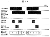
- FIG. 3 is a diagram schematically showing the difference in weight for each time.
- a dereverberation parameter that enables a comfortable voice call with clear voice that is less affected by reverberation in a video conference system that connects large rooms.
- the present invention is assumed to be used in a teleconference system used in a large room, etc., and reverberation noise (non-variable and variable reverberation components) is removed from an input signal to a plurality of microphones, and the microphone is directly used at the mouth.
- reverberation noise non-variable and variable reverberation components
- the microphone is directly used at the mouth.
- estimation of dereverberation parameters and real-time dereverberation processing using the dereverberation parameters are shown.
- the second embodiment in the dereverberation process, a plurality of past dereverberation parameters obtained in the dereverberation parameter estimation process are stored and the best filter is selected and used every time. Yes.
- estimation of parameters for removing reverberation and echo (reverberation) and real-time reverberation and echo removal processing using the same are shown.
- distributed processing for executing dereverberation parameter estimation processing on the server side is shown.
- the embodiment of the present invention may be implemented by software running on a general-purpose computer, or may be implemented by dedicated hardware or a combination of software and hardware.
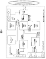
- FIG. 4 is a diagram showing a schematic hardware configuration of a conference system installed at each site of the remote conference according to the first embodiment of the present invention.
- the microphone array 105 collects audio waveforms in each conference room. It is assumed that the microphone array 105 includes a single microphone or a plurality of microphone elements.
- the collected analog voice waveform is converted from an analog signal to a digital signal by the A / D converter 104.
- the converted digital audio waveform is subjected to dereverberation processing in a central processing unit 102 (also referred to as a processor), and then converted into a packet via the HUB 108 and released to the network.
- a central processing unit 102 also referred to as a processor
- the central processing unit 102 reads a program stored in the nonvolatile memory 101 and parameters used in the program, and executes the program.
- a work memory used when executing the program is secured on the volatile memory 103, and storage areas for various parameters necessary for dereverberation are defined.
- the dereverberation parameter is estimated by the central processing unit 102 and stored in the volatile memory 103. Then, the stored reverberation parameter is read again by the central processing unit 102 and used for a new estimation process.
- the central processing unit 102 receives the voice waveform of the other base (far end) in the remote conference from the HUB 108 via the network.
- the received far-end speech waveform (digital speech waveform) is sent to the D / A converter 106 via the central processing unit 102, converted from a digital signal to an analog signal, and then the converted analog speech waveform is Are emitted from the speaker array 107.
- the speaker array 107 includes a single speaker element or a plurality of speaker elements. Also, the video information of each site is captured by a general camera 109 and transmitted to another site via the HUB 108. The video information of other bases is sent to the HUB 108 via the network, and further displayed on the display 110 installed at each base via the central processing unit 102. A configuration in which a plurality of cameras 109 or a plurality of displays 110 are installed may be employed.
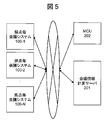
- FIG. 5 is a diagram showing an example of the overall configuration of the remote conference system of the present invention.
- the remote conference system includes N site conference systems 100-1, 100-2,... 100-N (the number of sites is N), an MCU 202 that controls the flow of audio and video at each site,
- the conference information calculation server 201 executes a calculation with a large processing amount that cannot be processed by a computer at each base, and each is connected via a network. Since this system is a system known to those skilled in the art, a detailed description thereof is omitted. Further, the conference information calculation server 201 may be configured to execute a part of processing necessary for dereverberation executed in the conference system at each site.
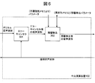
- FIG. 6 is a diagram showing a block configuration of processing (program) executed in the central processing unit 102 in the first embodiment of the present invention.
- the digital speech waveform obtained from the microphone array 105 via the A / D converter 104 is processed by the echo canceller 301 to remove the acoustic echo component.
- the acoustic echo component refers to a component mixed in the microphone array 105 after the sound waveform output from the speaker array 107 is reflected by the wall or ceiling of each base.
- the echo canceller 301 is realized by a configuration known to those skilled in the art, such as the NLMS method obtained via the HUB 108 in order to remove the acoustic echo component.
- a far-end speech waveform is used as a signal output from the speaker array 107.
- the speech waveform after the echo cancellation is sent to the dereverberation 302, the reverberation component is removed, and the speech waveform after the reverberation component is removed is output. Since the speech waveform is a time-series signal, the dereverberation program is executed every time a certain amount of speech waveform after A / D conversion is accumulated.
- FIG. 7 is a diagram for explaining the effect (an example) of the dereverberation 302.
- the microphone input signal shows a spectrogram obtained by converting the input waveform of one microphone constituting the microphone array 105 into the time-frequency domain.
- the horizontal axis is the time axis, and the vertical axis indicates the frequency.
- the brighter time-frequency component means that the volume is larger.
- a signal without reverberation (ideal) shows a waveform of only a direct sound without room reverberation. Comparing the microphone input signal and the signal without reverberation (ideal), it can be seen that the former component is diffused as ink bleeds in the time direction. This component is a reverberation component captured in the present invention.
- the signal after dereverberation (see (iii) in FIG. 7) is a waveform after processing by the dereverberation 302 of the present invention. It can be seen that the reverberation component is removed, and the signal approaches the ideal signal without reverberation.
- FIG. 8 is a diagram showing a detailed block configuration of the dereverberation (processing) 302 (see FIG. 6) according to the first embodiment.
- (I) Framing processing As shown in FIG. 8, the digital speech waveform after echo cancellation is sent to framing (processing) 401.
- the digital voice waveform is described as q (m, t), m is an index of a microphone constituting the microphone array 105, and t is a sample index of A / D conversion processing.
- framing 401 a sound waveform in units of frames is output each time a certain amount of digital sound waveform for each microphone element is accumulated. On the other hand, nothing is output until a certain amount is accumulated.
- the fixed amount is called a frame shift and is described as S (point).
- Such a frame shift is performed in order to accurately capture the transition of the sound because the frequency component is gradually changed and transmitted.
- the speech waveform for each microphone element output in framing 401 is a speech waveform for P points that is larger than the frame shift.
- the unit of the frame is called a frame index and is described as ⁇ .
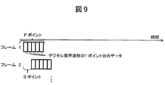
- FIG. 9 is a diagram for explaining frame formation and frame shift processing.
- frame 1 is composed of a speech waveform of data for P points immediately after the start of data acquisition.
- frame 2 is composed of a voice waveform of data for P points from a point shifted by S points from frame 1.
- the framing 401 outputs a speech waveform k (m, ⁇ ) in units of frames of each microphone element.
- the frequency decomposition (process) 402 converts the sound waveform of each microphone element into a time-frequency domain signal by a frequency conversion process generally used by those skilled in the art, such as a Fourier transform process. .
- the mth frame unit signal converted into the time-frequency domain signal is defined as Xm (f, ⁇ ).
- f is a frequency index in the time frequency domain.
- M means the number of microphones.
- the frequency domain signal of each microphone is sent to buffering (processing) 403 and online dereverberation (processing) 405.
- the buffering (processing) 403 stores a time domain signal, outputs the stored signal only when the storage amount reaches a certain amount, and outputs nothing otherwise.
- the amount stored in each microphone is T frames (for example, 300 frames). Since parameter estimation cannot be performed properly (stable) without using a certain amount of statistics, reverberation parameter estimation processing is executed after T frames of speech data are accumulated. For example, if a speaker is switched during a conference, the dereverberation parameter used in the online dereverberation 405 until now is not appropriate, so parameter estimation is performed again and the parameter is updated. However, since it is difficult to detect the switching of the speaker only from the speech waveform, in this embodiment, the dereverberation parameter is updated every T frame.
- the dereverberation process is executed using the current parameter until the next parameter estimation process is completed. That is, in the dereverberation process of the present embodiment, the latest estimation parameter is always used. If it is detected that the speaker has been switched, the dereverberation parameter may be updated at the timing of the speaker switching.
- the dereverberation parameter estimation (processing) 404 estimates parameters for performing dereverberation based on data for T frames output from the buffering 403, and outputs the estimated parameters. . Further details of the dereverberation parameter estimation (processing) 404 will be described later with reference to FIG.
- the online dereverberation (processing) 405 utilizes the estimated dereverberation parameters in real time.
- the dereverberation parameter estimation 404 performs processing every time data for T frames accumulates, whereas the online dereverberation 405 needs to perform dereverberation in real time. Perform the process.
- the online dereverberation 405 outputs a signal after removing the reverberation component in the data for one frame including the reverberation.
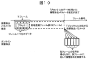
- FIG. 10 is a timing chart for explaining the execution timing of the dereverberation parameter estimation 404 and the online dereverberation 405.
- the dereverberation parameter estimation 404 as described above, parameter estimation processing is executed every time data for T frames is obtained.
- Each processing delay frame length (U frame) until the estimated parameter starts to be used in the online dereverberation 405 depends on the processing amount in the dereverberation parameter estimation 404 and is different.
- the online dereverberation 405 performs dereverberation on the time domain signal of each frame using the latest dereverberation parameter obtained at the time of processing.
- time domain conversion (processing) 406 performs frequency domain to time domain conversion processing such as inverse Fourier transform on the frequency domain signal for one frame for each microphone. By doing so, the time domain signal is restored, and the returned time domain signal is output as a speech waveform after dereverberation. By executing this time domain conversion process, it is possible to adjust the audio power of the overlapping area for (PS) points in each frame.
- frequency domain to time domain conversion processing such as inverse Fourier transform
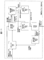
- FIG. 11 is a diagram showing a detailed block configuration of the dereverberation parameter estimation (process) 404.
- the dereverberation parameter estimation 404 is configured to sequentially improve the dereverberation performance by iterative calculation. That is, in this embodiment, when two types of parameters X and Y (here, X is a non-variable dereverberation parameter and Y is a variable dereverberation parameter), X is first fixed, The appropriate value of Y is obtained by changing the value. Next, X is changed to obtain an appropriate value of X. As described above, FIG. 11 shows a process of alternately obtaining and converging X and Y. In the dereverberation parameter estimation 404, processing is performed independently for each frequency index. Therefore, a configuration in which this dereverberation parameter estimation process is executed by a central processing unit (processor) that differs for each frequency is also possible.
- processor central processing unit
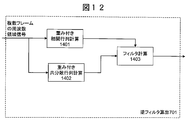
- FIG. 12 is a diagram showing a detailed configuration of the inverse filter calculation (processing) 701.
- a filter calculation (processing) 1403 calculates a linear filter according to equation (2). Since the reverberation component is a component derived from a past signal, Expression (2) is an arithmetic expression for calculating the correlation between the current signal, the past signal, and the past signals. . If only the correlation between the current signal and the past signal is obtained, the past signal may be excessively removed from the current signal.Therefore, in order to avoid excessive signal removal, the correlation between the past signals is calculated. The calculation also takes into account. Note that the calculation for calculating the correlation is performed on the audio signals for T frames.
- Equation (3) is an arithmetic expression for calculating the correlation between past signals.
- H is an operator representing a conjugate transpose of a matrix or a vector.
- Equation (2) is calculated by equation (4) in weighted correlation matrix calculation 1401.
- Expression (4) is an arithmetic expression for calculating the correlation between the current signal and the past signal.
- ′ in Expression (3) represents an operator representing transposition of a matrix or a vector.
- I an operator representing the Kronecker-Delta product.
- Equation (3) U f, ⁇ (i) is defined by Equation (5).
- D and L1 be predetermined parameters.
- D is preferably set to a frame length corresponding to the initial reverberation among the reverberant components.
- L1 is a parameter corresponding to the continuous frame length of the rear reverberation, and is desirably set to a large value in an environment where the rear reverberation is large.
- R x, f, ⁇ (i) is a matrix output by the linear reverberation component weight calculation 707. When the linear reverberation component weight calculation (processing) 707 is not performed, or when the inverse filter calculation 701 is executed for each T frame data for the first time, R x, f, ⁇ (i) is set in the unit matrix. .
- “vec” is an operator for converting a matrix into a vector. An example of converting the matrix A into a vector by the vec operator is shown in Expression (6).
- a mn means the m-th row and n-th column component of the matrix A.
- evec is an inverse operator of the vec operator and converts a vector into a matrix.
- a matrix in which the number of rows of the output matrix matches the number of microphones is output.
- a f obtained by Expression (2) is classified for each block by Expression (7).
- the inverse filter calculation 701 outputs A f and ends the process.
- the linear reverberation component elimination (processing) 702 uses the Af output from the inverse filter calculation 701 to obtain the signal g f, ⁇ (i) from which the non-variable reverberation component has been removed by the equation (8). Get by.
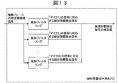
- the linear reverberation component elimination (processing) 702 can be regarded as a method of obtaining a dereverberation signal for each channel by operating a separate FIR filter for each microphone channel.
- FIG. 13 shows a concept that is understood as a configuration in which dereverberation is performed for each microphone channel.
- the linear dereverberation process according to the present embodiment is executed for all the time-frequency signals for T frames.
- the signal after linear reverberation removal is sent to residual reverberation / direct sound separation 703.
- Residual Reverberation / Direct Sound Separation Processing Residual reverberation / direct sound separation (processing) 703 separates the signal after linear reverberation removal into a direct sound and a reverberation sound (estimated value).
- FIG. 14 is a diagram showing a detailed block configuration of the residual reverberation / direct sound separation 703.
- the residual reverberation / direct sound separation processing is also executed for all time frequency signals for T frames.
- the estimated value of the dereverberation signal for each frame is obtained by superimposing the filter coefficients W n, f, ⁇ (i) estimated by the direct sound filter coefficient estimation 1102 on the time-frequency signal of each frame, as shown in Expression (9). Is calculated.
- n is a variable indicating the index of the sound source, and is an integer from 1 to N. Even when N is the number of sound sources and there are a plurality of sound sources, by setting N to 2 or more, reverberation removal and direct sound separation of a plurality of sound sources can be performed simultaneously.
- a direct sound filter estimation (processing) 1102 calculates a filter (mirror filter) W n, f, ⁇ (i) for extracting a direct sound for each sound source, using Expression (10). Equation (10) is substantially equivalent to determining the ratio of the direct sound power to the total power (direct sound power / (direct sound power + residual reverberation power)).
- R s (n), f, ⁇ (i) is a covariance matrix for each sound source and for each frame, and in the target sound variance estimation (processing) 1104 for each time, using Equation (11) Calculated.
- v s (n), f, ⁇ (i) , C s (n), f are parameters relating to the nth direct sound component, and are parameters that are sequentially updated in the iterative calculation. is there.
- the initial value of v s (n), f, ⁇ (i) is 1, and C s (n), f is a random positive definite Hermitian matrix.
- the residual reverberation component is calculated as shown in Expression (12) by superimposing W rev, l, m, f, ⁇ (i) on the time frequency signal of each frame.
- Equation (13) is substantially equivalent to determining the ratio of the residual reverberation power to the total power (residual reverberation power / (direct sound power + residual reverberation power)).
- R rev, l, m, f, ⁇ (i) is a covariance matrix for each tap index of the inverse filter and for each frame.
- R rev, l, m, f, ⁇ (i) is a covariance matrix for each tap index of the inverse filter and for each frame.
- X f, ⁇ (i) (m) is a time frequency domain signal of the m-th microphone having the frequency index f and the frame index ⁇ (i).
- C rev, l, m, f is a covariance matrix of the residual reverberation component for each tap index and microphone index, and is a parameter that is sequentially updated in the iterative calculation.
- the initial value is a random positive definite Hermitian matrix.
- the separated reverberation estimation value and the direct sound estimation value are sent to the residual reverberation parameter estimation (processing) 704 and the direct sound parameter estimation (processing) 705, respectively.
- the residual reverberation parameter estimation (processing) 704 estimates parameters such as statistics of variable reverberation components.
- FIG. 15 is a diagram showing details of residual reverberation parameter estimation (processing) 704.
- residual reverberation secondary statistic calculation (processing) 1301 applies the equation (15) to the residual reverberation estimation value sent from the residual reverberation / direct sound separation 703, and performs residual reverberation for each frame. Calculate the second order statistics of the component (power of residual reverberation).
- V rev, l, m, f, ⁇ (i) is sent to the spindle calculation (processing) 1302, and C rev, l, m, f is updated by equation (16).
- the direct sound parameter estimation (processing) 705 estimates parameters such as direct sound statistics.
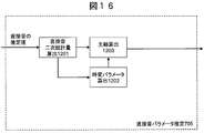
- FIG. 16 is a diagram showing details of the direct sound parameter estimation 705.
- the direct sound secondary statistic calculation (processing) 1201 applies the equation (17) to the residual reverberation estimation value sent from the residual reverberation / direct sound separation 703, and for each frame of each sound source.
- the direct sound covariance matrix (the power of the direct sound input to each microphone and the time difference component until the signal reaches each microphone) is calculated.
- the time-varying parameter calculation 1202 updates v s (n), f, ⁇ (i ) according to the equation (18).
- the time-varying parameter means information including a time difference until sound directly reaches N microphones.
- the spindle calculation 1203 updates C s (n), f according to the equation (19).
- the main axis calculation takes into account the time difference until the sound directly reaches N microphones, and the main axis of the N-dimensional manifold (ellipse) in N dimensions (N microphones) (direct input to each microphone). This means that the variation in sound power) is determined.
- the main axis calculation 1203 is a process for calculating the power variation of the audio signal transmitted to each microphone
- the time-varying parameter calculation 1202 is a process for calculating the time difference of the audio signal (direct sound) until it reaches each microphone. is there. More specifically, when two microphones m1 and m2 are installed, the slope of a straight line connecting the origin and the plot when the power of the audio signal transmitted to m1 and m2 is plotted on the m1-m2 plane. Represents the principal axis, and the principal axis length (distance from the origin to the plot) represents a time-varying parameter (time difference).
- Convergence determination 706 is a scale similar to that in general iterative calculation, such as whether or not the iterative calculation has been executed a predetermined number of times, and whether or not the difference between the estimated parameter value and the pre-estimation value is less than or equal to a predetermined value. Determine if the calculation has converged. If converged, the dereverberation parameter is output, and the dereverberation parameter estimation 404 block ends.
- the linear reverberation component weight calculation (process) 707 updates R x, f, ⁇ (i ) according to the equation (20).
- N is the number of sound sources.
- the weight for each time is fed back to the inverse filter calculation 701.
- the calculation is started with a weighting factor of 1. Then, the weighting factor can be converged to an appropriate value by repeating the calculation of FIG.
- FIG. 17 is a diagram showing a specific configuration of online dereverberation (processing) 405.
- the online dereverberation (processing) 405 is configured to increase the parameter estimation accuracy by sequential calculation.
- (I) Buffering Processing Buffering (processing) 801 stores a time-frequency domain signal for each frame in the volatile memory 103.
- the stored time frequency domain signal is L1 frames (for example, 5 frames) counted from the latest time domain signal among the signals in the T frame.
- an audio signal for a predetermined frame is accumulated by the buffering process 801 and is set as a processing target.
- the linear reverberation component elimination (processing) 702 receives the stored time domain signals for L1 frames, and removes the reverberation components using an inverse filter.
- the applied inverse filter is a filter included in the dereverberation parameter output from the dereverberation parameter estimation (process) 404.
- the reverberation direct sound separation (processing) 703 receives a reverberation component removal signal from the linear reverberation component elimination (processing) 702, separates it into a direct sound and a residual reverberation component, and outputs a direct sound. To do. At this time, the initial value of v s (n), f, ⁇ is 1. Further, C s (n), f is a covariance matrix included in the dereverberation parameter output from the dereverberation parameter estimation (process) 404.
- the direct sound variance estimation (processing) 802 is the same flow as the direct sound parameter estimation 705 in the residual removal parameter estimation 404, and is processed according to Expression (21) (the same expression as Expression (18)). Calculate v s (n), f, ⁇ (i) in the frame.
- the convergence determination (processing) 706 performs convergence determination of the obtained parameters using parameters such as the estimated direct sound dispersion. If it is determined that the signal has converged, the convergence determination (process) 706 outputs the estimated direct sound and ends the process. In other cases, the convergence determination (process) 706 executes the residual reverberation direct sound separation (process) 703 again based on the estimated direct sound dispersion.
- FIG. 18 is a diagram showing a configuration of dereverberation (processing) 302 according to the second embodiment of the present invention.
- the configuration and processing from the framing (processing) 401 to the dereverberation parameter estimation (processing) 404 and the time domain transform (processing) 406 are the configurations shown in FIG. Is the same.
- parameter writing control (processing) 903 is a process of switching whether to register the dereverberation parameter output from the dereverberation parameter estimation 404 as a new dereverberation parameter.
- the dereverberation parameter DB 901 stores a predetermined number of dereverberation parameters in the DB.
- the dereverberation parameter with the oldest stored time is discarded, and the new dereverberation parameter is stored instead.
- a configuration that discards the dereverberation parameter with the smallest likelihood value (likelihood here: synonymous with error) and stores the new dereverberation parameter instead.
- the dereverberation parameter to be discarded may be configured to discard the dereverberation parameter stored at the same timing for each frequency.
- each of the online dereverberation (process) 405-1 to 405-A removes the dereverberation component by online processing for each dereverberation parameter. Execute the process.
- Optimal dereverberation sound selection (processing) 902 selects one dereverberation sound among the dereverberation sounds removed by each dereverberation parameter. For example, a configuration in which the component with the smallest volume among the dereverberation sounds is selected or a configuration in which the dereverberation sound with the largest likelihood value is selected may be employed. Further, the sound volume component and the likelihood value may be calculated using values averaged in the frequency direction.
- the selected dereverberation sound is sent to the time domain conversion (processing) 406, converted into a time domain signal and output.
- the time domain conversion (processing) 406 For example, it is possible to remove dereverberation using the parameter 1 for an audio signal in a low frequency region and the parameter 2 for an audio signal in a high frequency region.
- an optimum filter can be obtained for each frequency, and accurate dereverberation processing can be executed even in a scene where a plurality of people speak at the same time.
- the dereverberation parameters obtained in the past are accumulated, and the optimum parameters obtained in the past can be used even when the speaker is switched. Will be able to.
- the third embodiment relates to a configuration capable of executing the dereverberation and the echo canceller in the same framework, and improving the performance of both the dereverberation and the echo canceller.
- Reverberation removal and echo canceller cancellation can be operated separately, and this configuration is simple (see FIG. 6).
- the filter of the echo canceller always changes its shape, the voice that cannot be erased by the echo canceller may adversely affect the dereverberation. Therefore, rather than optimizing the dereverberation and the echo canceller separately, the performance of the entire system can be further improved by optimizing the two simultaneously (in consideration of the influence of each other).
- a configuration for realizing this is according to the third embodiment.
- FIG. 19 is a diagram schematically showing an internal configuration of a central processing unit that executes processing according to the third embodiment.
- a dereverberation and echo canceller 2001 receives a digital speech waveform (microphone input signal) and a far-end digital speech waveform (reference signal), and performs dereverberation processing and Echo cancellation processing is executed at the same time, and the sound waveform after dereverberation / echo cancellation is output.
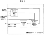
- FIG. 20 is a diagram illustrating a specific configuration of the dereverberation and echo canceller 2001.
- An off-line parameter estimation (processing) 1800 receives a digital speech waveform (microphone input signal) and a far-end digital speech waveform (reference signal), and estimates parameters for dereverberation and acoustic echo cancellers.
- the offline parameter estimation 1800 executes estimation processing every time a plurality of frames (T frames) of time domain signals are obtained.
- T frames The detailed configuration and processing of the offline parameter estimation (processing) 1800 will be described later with reference to FIG.
- the online acoustic echo / dereverberation (processing) 2301 uses the parameters estimated by the offline parameter estimation 1800 to perform dereverberation and acoustic echo component removal for the time-frequency domain signal for each frame.
- the detailed configuration and processing of the online acoustic echo / dereverberation (processing) 2301 will be described later with reference to FIG.
- the time domain conversion 406 converts the time frequency domain signal from which the reverberation component and the acoustic echo component are removed into a time domain signal and outputs it.
- FIG. 21 is a diagram showing a specific block configuration of offline parameter estimation (processing) 1800.
- Both the digital audio waveform obtained by converting the audio waveform obtained by the microphone array 105 into a digital signal and the far-end digital audio waveform (referred to as a reference signal) are subjected to framing (processing) 401 and frequency decomposition (processing) 402. Converted to a time frequency domain signal.
- X ref, b (f, ⁇ ) [X ref, 1 (f, ⁇ ) ,..., X ref, B (f, ⁇ ) ] and B is the number of speaker elements.
- reverberation / acoustic echo cancellation parameter estimation (processing) 1801 is executed, and reverberation / acoustic echo cancellation parameters are output.
- a detailed configuration and processing of the reverberation / acoustic echo cancellation parameter estimation (processing) 1801 will be described later with reference to FIG.
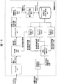
- FIG. 22 is a diagram showing a specific block configuration of reverberation / acoustic echo cancellation parameter estimation (processing) 1801. Since the linear reverberation component elimination 702, the residual reverberation parameter estimation 704, the direct sound parameter estimation 705, and the convergence determination 706 are configured and processed as described above, detailed description thereof is omitted.
- the inverse filter calculation (process) 1908 obtains an inverse filter for removing reverberation (non-fluctuating component) by the above-described method (first embodiment).
- a signal obtained by canceling the linear acoustic echo using the result of the linear acoustic echo cancellation filter calculation (processing) 1901 may be used instead of the microphone input signal.
- the inverse filter calculation 1908 has a function of linear acoustic echo cancellation (processing) 1902.
- the inverse filter calculation 1908 uses the echo cancellation filter calculated by the linear acoustic echo cancellation filter calculation 1901 to cancel the acoustic echo included in the input signal (frequency domain signal of a plurality of frames), and then reverses the dereverberation. Calculate the filter.
- the linear acoustic echo cancellation filter calculation (process) 1901 is for acoustic echo cancellation using a signal from which the reverberation component is removed using the inverse filter obtained by the inverse filter calculation 1908 described above instead of the microphone input signal. You may ask for a filter.
- the linear acoustic echo cancellation filter calculation (processing) 1901 has a function of linear reverberation component cancellation (processing) 702. That is, the linear acoustic echo cancellation filter calculation (process) 1901 calculates a linear acoustic echo cancellation filter after removing the reverberation using the reverberation elimination inverse filter calculated in the inverse filter calculation 1908.
- J p, f , J u, f, ⁇ (i) and J q, f are defined as Expressions (23), (24), and (25), respectively.
- the acoustic echo canceling filter is divided into filters for each tap as shown in Expression (26).
- the linear acoustic echo elimination (processing) 1902 is a signal g 2, f, ⁇ in which the acoustic echo component is eliminated using the acoustic echo elimination filter calculated in the linear acoustic echo cancellation filter calculation 1901.
- (I) is obtained according to equation (27).
- Residual reverberation / residual acoustic echo / direct sound separation (processing) 1904 is a residual reverberation / direct sound separation 703 (first embodiment).
- the residual acoustic echo extraction filter W ref, l, b, f, ⁇ (i) obtained by the equation (28 ) is superimposed on g 2, f, ⁇ (i) .
- the residual acoustic echo estimated value y ref, l, b, f, ⁇ (i) is calculated according to the equation (29).
- R ref, l, b, f, ⁇ (i) can be obtained by equation (30).
- C ref, l, b, f are parameters updated by repeated calculation, and the initial value is a random positive definite Hermitian matrix.
- Residual acoustic echo parameter estimation (processing) 1906 is the same as residual reverberation parameter estimation (processing) 704 (FIG. 11: first embodiment) for C ref, l, b, f . Update by processing. Since the detailed description is as described above, it is omitted here.
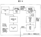
- FIG. 24 is a diagram showing a specific configuration of online (real-time) acoustic echo / dereverberation (processing) 2301.
- the digital audio waveform (microphone input audio signal) and the far-end digital audio waveform (reference signal) are subjected to framing (processing) 401 and frequency decomposition (processing) 402, and further buffered by buffering (processing) 403. .
- the buffered speech waveform is sent to linear acoustic echo / dereverberation (processing) 1902.
- the linear acoustic echo / dereverberation removal (processing) 1902 removes non-variable reverberation and acoustic echo components from the data of each frame of the received speech waveform.
- the residual reverberation / residual acoustic echo / direct sound separation (processing) 1904 extracts only the direct sound.
- the direct sound variance estimation (processing) 802 receives the direct sound extracted from the residual reverberation / residual acoustic echo / direct sound separation (processing) 1904 , and calculates v s (n), f, ⁇ .
- the details of this process are the same as described in the first embodiment, and a description thereof will be omitted.
- the convergence determination (processing) 706 determines whether or not the variance estimation has converged, and outputs the estimated direct sound component if it has converged.
- the estimated direct sound dispersion value is returned to the residual reverberation / residual acoustic echo / direct sound separation 1904, and the direct sound estimation process is executed again. The details of the processing are also as described in the first embodiment.
- a dereverberation parameter having a particularly large calculation amount is executed by the conference information calculation server 201, and other real-time dereverberation processing is performed for each base.
- the present invention relates to a distributed configuration as executed in the conference system 100.
- FIG. 25 is a diagram showing an overall system schematic configuration according to the fourth embodiment.
- framing (processing) 401, frequency decomposition (processing) 402, and buffering (processing) 403 are executed by the conference system 100 for each base. Then, after the time frequency domain signals for T frames are accumulated, the conference system 100 for each site transmits the time frequency domain signal to the conference information calculation server 201.
- the conference information calculation server 201 receives a time-frequency domain signal for T frames sent from the conference system 100 for each base, and executes dereverberation parameter estimation 404 on the signal.
- the conference information calculation server 201 transmits the estimated dereverberation parameter from the server to the conference system 100 for each site.
- the conference system 100 for each site executes online dereverberation 405 and time domain conversion 406 every time a time frequency domain signal for each frame is obtained, and acquires dereverberation sound (direct sound with dereverberation removed).
- the conference information calculation server 201 may include the configuration of the reverberation / acoustic echo cancellation parameter estimation (processing) 1801 shown in the third embodiment instead of the configuration of the dereverberation parameter estimation (processing) 404.
- the conference system 100 for each base includes the configuration of the online acoustic echo / dereverberation (processing) 2301 shown in the third embodiment, instead of the configuration of the online dereverberation (processing) 405.
- the dereverberation parameter is stored in a memory such as a volatile memory, and is sequentially updated according to the processing.
- the memory includes at least parameters of a linear filter for removing non-variable reverberation components included in the voice input signal and parameters of a nonlinear filter for removing variable reverberation components contained in the voice input signal.
- a processor such as a central processing unit estimates and updates a dereverberation parameter for obtaining a direct sound by removing a dereverber component included in the voice input signal, and the dereverberation parameter is set to a linear filter parameter and a nonlinear parameter.
- filter parameters in memory Store as filter parameters in memory.
- the processor (inverse filter calculation 701 and linear reverberation component elimination 702) reads the parameters of the linear filter from the memory, removes the non-variable reverberation component contained in the speech input signal by the linear filter, and performs linear processing. An estimate of the dereverberation signal is generated.
- the processor (residual reverberation / direct sound separation 703) reads the parameters of the non-linear filter from the memory and uses the non-linear filter to determine the variable reverberation component and the direct sound component included in the estimated value of the linear dereverberation signal. Generate an estimate.
- the processor (residual reverberation parameter estimation 704 and direct sound parameter estimation 705) performs principal axis calculation (see FIGS. 15 and 16) based on the variable reverberation component and the direct sound estimation value, and calculates the parameters of the nonlinear filter.
- the parameters of the variable reverberation component and the direct sound component are updated.
- the processor (linear reverberation component weight calculation 707 and inverse filter calculation 701) sequentially updates the parameters of the linear filter based on the updated parameters of the variable reverberation component and the direct sound component.
- the parameter of the linear filter for removing the non-variable reverberation component is fixed to a certain value
- the parameter of the nonlinear filter for removing the variable reverberation component is estimated, and again in light of the obtained estimated value.
- the parameter estimation process is repeated until the estimation parameters converge by updating the parameters of the linear filter.
- the processor (linear reverberation component weight calculation 707) reflects the time zone in which the sum of the variable reverberation component and the direct sound component is large in the audio input signal according to the updated parameters of the variable reverberation component and the direct sound component.
- the filter weight coefficient is determined (see FIG. 3), and the linear filter parameters are updated. In this way, by reducing the weight of the filter coefficient in the time zone where the transfer function of the linear filter may fluctuate, the signal is extracted with an increased specific gravity in the time zone where a large non-variable reverberation component exists. Therefore, it is possible to reduce the influence that the estimation accuracy of the transfer function falls.
- audio signals from a plurality of microphones are assumed as audio input signals.
- the processor (residual reverberation / direct sound separation 703) generates an estimated value of the direct sound component and an estimated value of the variable reverberation component included in the audio signal from each of the plurality of microphones. Then, the processor (residual reverberation parameter estimation 704 and direct sound parameter estimation 705) extracts secondary statistics of the estimated values of the direct sound component and the variable reverberation component from the respective microphones, and extracts a plurality of secondary statistics from the secondary statistics.
- Information representing the power variations of the direct sound component and the variable reverberation component of the sound signal of the microphone is used as a parameter for the variable reverberation component and the direct sound component.
- each microphone is different when the distance from the sound source (speech, sound reflecting surface (reflecting sound emitted from the sound source) on a reflector such as a wall or a person) to each microphone is different. It is possible to estimate a parameter capable of accurately removing reverberation in consideration of variations in the power of the voice input to the.
- the first embodiment further proposes a dereverberation apparatus having the above-described dereverberation parameter estimation apparatus.
- the processor central processing unit acquires the dereverberation parameter from the dereverberation parameter estimation device, and removes the non-variable reverberation component and the variable reverberation component from the speech input signal.
- the direct sound component is output.
- the processor linear reverberation component elimination 702 estimates a linear dereverberation signal by removing non-variable reverberation components from the speech input signal by a linear filter.
- the processor (residual reverberation / direct sound separation 703) separates the variable reverberation component and the direct sound component from the linear dereverberation signal by a non-linear filter. Then, the processor (direct sound variance estimation 802 and convergence determination 706) learns the power change for each time in the direct sound component, and outputs the direct sound component in which the power change is converged. In this way, reverberation can be accurately removed in real time. In addition, since direct sound variance estimation (processing that updates the sound directly according to the sound power that changes with time) is performed, the direct sound without distortion follows the change in the sound power that occurs over time. Can be extracted.
- the second embodiment proposes another dereverberation device.
- the apparatus (FIG. 18) has a dereverberation parameter database that stores the dereverberation parameters obtained by the dereverberation parameter estimation apparatus. This database stores all or part of the dereverberation parameters obtained by estimation in the past.
- the processor online dereverberation 450-1 to 405-A corresponding to the installed microphone acquires a plurality of dereverberation parameters corresponding from the dereverberation parameter database, and each of the plurality of dereverberation parameters is obtained.
- Is used to remove the non-variable reverberation component and the variable reverberation component from the audio input signal generate a plurality of direct sound components, and output an optimum direct sound component among the plurality of direct sound components.
- the dereverberation process can be executed using the estimated parameters, the dereverberation process can be performed quickly, thereby contributing to real-time processing.
- the parameters of the linear reverberation filter for removing the non-variable reverberation component included in the speech input signal and the non-variable echo component included in the speech input signal are removed from the memory.
- a parameter of a non-linear filter for removing a variable reverberation component and a variable echo component included in the voice input signal is estimated.
- the processor central processing unit
- the reverberation filter parameters, the linear echo cancellation filter parameters, and the nonlinear filter parameters are stored in the memory.
- the processor (the inverse filter calculation 1908 and the linear acoustic echo cancellation filter calculation 1901) reads the parameters of the linear reverberation filter parameters and the parameters of the linear echo cancellation filter from the memory, and performs the linear reverberation filter and the linear echo cancellation filter. To remove the non-variable reverberation component and non-variable echo component contained in the voice input signal to generate an estimated value of the linear reverberation / echo removal signal. In this case, the inverse filter calculation 1908 and the linear acoustic echo cancellation filter calculation 1901 calculate the filters using the processing results of each other.
- the linear acoustic echo cancellation filter calculation 1901 calculates a linear acoustic echo cancellation filter using a signal obtained by removing the non-variable reverberation component from the audio input signal.
- the inverse filter calculation 1908 calculates an inverse filter using a signal obtained by removing the non-variable acoustic echo component from the voice input signal.
- the processor uses a nonlinear filter to change the variable reverberation component, the variable echo component, and the direct sound included in the estimated value of the linear reverberation / echo removal signal. Generate an estimate of the component.
- the processor (residual reverberation parameter estimation 704, direct sound parameter estimation 705, and residual acoustic echo parameter estimation 1906) is configured to determine the parameters of the nonlinear filter based on the variable reverberation component, the variable echo component, and the direct sound estimate.
- the parameters of the variable reverberation component, the variable echo component, and the direct sound component are updated.
- the processor (linear reverberation / echo component weight calculation 1907, linear acoustic echo cancellation filter calculation 1901, and inverse filter calculation 1908) is based on the updated parameters of the variable reverberation component, variable echo component, and direct sound component.
- the parameters of the linear reverberation filter and the linear echo cancellation filter are sequentially updated. In this way, by executing dereverberation and echo cancellation within the same framework, it is possible to estimate parameters that can improve the processing accuracy of both.
- the fourth embodiment proposes a configuration (FIG. 25) in which a reverberation parameter estimation process that places a load on the process is executed in the computer server of the conference system.
- the present invention can also be realized by software program codes that implement the functions of the embodiments.
- a storage medium in which the program code is recorded is provided to the system or apparatus, and the computer (or CPU or MPU) of the system or apparatus reads the program code stored in the storage medium.
- the program code itself read from the storage medium realizes the functions of the above-described embodiments, and the program code itself and the storage medium storing the program code constitute the present invention.
- a storage medium for supplying such program code for example, a flexible disk, CD-ROM, DVD-ROM, hard disk, optical disk, magneto-optical disk, CD-R, magnetic tape, nonvolatile memory card, ROM Etc. are used.
- an OS operating system
- the computer CPU or the like performs part or all of the actual processing based on the instruction of the program code.
- the program code is stored in a storage means such as a hard disk or a memory of a system or apparatus, or a storage medium such as a CD-RW or CD-R
- the computer (or CPU or MPU) of the system or apparatus may read and execute the program code stored in the storage means or the storage medium when used.
- control lines and information lines are those that are considered necessary for the explanation, and not all control lines and information lines on the product are necessarily shown. All the components may be connected to each other.
- DESCRIPTION OF SYMBOLS 100 Conference system for every base, 101 ... Nonvolatile memory, 102 ... Central processing unit, 103 ... Volatile memory, 104 ... A / D converter, 105 ... Microphone array, 106 ... D / A converter, 107 ... Speaker array , 108 ... HUB, 109 ... camera, 110 ... display, 201 ... conference information calculation server, 202 ... MCU, 301 ... echo canceller, 302 ... dereverberation, 401 ... framing, 402 ... frequency decomposition, 403 ... buffering, 404 ... dereverberation parameter estimation, 405 ... online dereverberation, 406 ... time domain transform, 701 ...
- Linear acoustic echo cancellation, 904 residual reverberation / residual acoustic echo / direct sound separation, 1906 ... residual acoustic echo parameter estimation, 1907 ... linear reverberation / echo component weight calculation, 1908 ... inverse filter calculation, 2001 ... dereverberation and echo canceller, 2301 ... online acoustic echo ⁇ Reverberation removal
Landscapes
- Engineering & Computer Science (AREA)
- Signal Processing (AREA)
- Physics & Mathematics (AREA)
- Acoustics & Sound (AREA)
- Health & Medical Sciences (AREA)
- Quality & Reliability (AREA)
- Computational Linguistics (AREA)
- Audiology, Speech & Language Pathology (AREA)
- Human Computer Interaction (AREA)
- Multimedia (AREA)
- Computer Networks & Wireless Communication (AREA)
- General Health & Medical Sciences (AREA)
- Otolaryngology (AREA)
- Circuit For Audible Band Transducer (AREA)
- Cable Transmission Systems, Equalization Of Radio And Reduction Of Echo (AREA)
Priority Applications (2)
| Application Number | Priority Date | Filing Date | Title |
|---|---|---|---|
| US14/379,144 US9288576B2 (en) | 2012-02-17 | 2013-02-15 | Dereverberation parameter estimation device and method, dereverberation/echo-cancellation parameter estimation device, dereverberation device, dereverberation/echo-cancellation device, and dereverberation device online conferencing system |
| CN201380009596.5A CN104115223B (zh) | 2012-02-17 | 2013-02-15 | 混响去除参数估计装置以及方法、混响/回波去除参数估计装置、混响去除装置、混响/回波去除装置、以及混响去除装置在线会议系统 |
Applications Claiming Priority (2)
| Application Number | Priority Date | Filing Date | Title |
|---|---|---|---|
| JP2012-033159 | 2012-02-17 | ||
| JP2012033159A JP5897343B2 (ja) | 2012-02-17 | 2012-02-17 | 残響除去パラメータ推定装置及び方法、残響・エコー除去パラメータ推定装置、残響除去装置、残響・エコー除去装置、並びに、残響除去装置オンライン会議システム |
Publications (1)
| Publication Number | Publication Date |
|---|---|
| WO2013122183A1 true WO2013122183A1 (fr) | 2013-08-22 |
Family
ID=48984292
Family Applications (1)
| Application Number | Title | Priority Date | Filing Date |
|---|---|---|---|
| PCT/JP2013/053645 Ceased WO2013122183A1 (fr) | 2012-02-17 | 2013-02-15 | Dispositif et procédé d'estimation de paramètre de déréverbération, dispositif d'estimation de paramètre de déréverbération/suppression d'écho, dispositif de déréverbération, dispositif de déréverbération/suppression d'écho, et système de conférence en ligne à dispositif de déréverbération |
Country Status (4)
| Country | Link |
|---|---|
| US (1) | US9288576B2 (fr) |
| JP (1) | JP5897343B2 (fr) |
| CN (1) | CN104115223B (fr) |
| WO (1) | WO2013122183A1 (fr) |
Cited By (1)
| Publication number | Priority date | Publication date | Assignee | Title |
|---|---|---|---|---|
| CN103956170A (zh) * | 2014-04-21 | 2014-07-30 | 华为技术有限公司 | 一种消除混响的方法、装置和设备 |
Families Citing this family (28)
| Publication number | Priority date | Publication date | Assignee | Title |
|---|---|---|---|---|
| EP2884491A1 (fr) * | 2013-12-11 | 2015-06-17 | Fraunhofer-Gesellschaft zur Förderung der angewandten Forschung e.V. | Extraction de sons réverbérants utilisant des réseaux de microphones |
| JP6349899B2 (ja) * | 2014-04-14 | 2018-07-04 | ヤマハ株式会社 | 放収音装置 |
| US9607627B2 (en) * | 2015-02-05 | 2017-03-28 | Adobe Systems Incorporated | Sound enhancement through deverberation |
| CN106448691B (zh) * | 2015-08-10 | 2020-12-11 | 深圳市潮流网络技术有限公司 | 一种用于扩音通信系统的语音增强方法 |
| CN106485192B (zh) * | 2015-09-02 | 2019-12-06 | 富士通株式会社 | 用于图像识别的神经网络的训练方法和装置 |
| EP3354043B1 (fr) * | 2015-10-14 | 2021-05-26 | Huawei Technologies Co., Ltd. | Système de suppression adaptative d'échos |
| US9813811B1 (en) | 2016-06-01 | 2017-11-07 | Cisco Technology, Inc. | Soundfield decomposition, reverberation reduction, and audio mixing of sub-soundfields at a video conference endpoint |
| CN110088834B (zh) * | 2016-12-23 | 2023-10-27 | 辛纳普蒂克斯公司 | 用于语音去混响的多输入多输出(mimo)音频信号处理 |
| DE112017006486T5 (de) * | 2016-12-23 | 2019-09-12 | Synaptics Incorporated | Online-enthallungsalgorithmus basierend auf gewichtetem vorhersagefehler für lärmbehaftete zeitvariante umgebungen |
| US20180218747A1 (en) * | 2017-01-28 | 2018-08-02 | Bose Corporation | Audio Device Filter Modification |
| US10389885B2 (en) | 2017-02-01 | 2019-08-20 | Cisco Technology, Inc. | Full-duplex adaptive echo cancellation in a conference endpoint |
| US11373667B2 (en) * | 2017-04-19 | 2022-06-28 | Synaptics Incorporated | Real-time single-channel speech enhancement in noisy and time-varying environments |
| CN107316649B (zh) * | 2017-05-15 | 2020-11-20 | 百度在线网络技术(北京)有限公司 | 基于人工智能的语音识别方法及装置 |
| EP3460795A1 (fr) | 2017-09-21 | 2019-03-27 | Fraunhofer-Gesellschaft zur Förderung der angewandten Forschung e.V. | Processeur de signaux et procédé pour fournir un signal audio traité afin de réduire le bruit et la réverbération |
| US10504529B2 (en) | 2017-11-09 | 2019-12-10 | Cisco Technology, Inc. | Binaural audio encoding/decoding and rendering for a headset |
| CN110111804B (zh) * | 2018-02-01 | 2021-03-19 | 南京大学 | 基于rls算法的自适应去混响方法 |
| US10448154B1 (en) | 2018-08-31 | 2019-10-15 | International Business Machines Corporation | Enhancing voice quality for online meetings |
| CN109712637B (zh) * | 2018-12-21 | 2020-09-22 | 珠海慧联科技有限公司 | 一种混响抑制系统及方法 |
| CN111933170B (zh) * | 2020-07-20 | 2024-03-29 | 歌尔科技有限公司 | 语音信号的处理方法、装置、设备及存储介质 |
| CN113963712B (zh) * | 2020-07-21 | 2025-07-25 | 华为技术有限公司 | 滤除回声的方法、电子设备和计算机可读存储介质 |
| JP7526906B2 (ja) * | 2020-08-20 | 2024-08-02 | 武 服部 | 放送装置、受信装置、及び、エコーキャンセル方法 |
| CN112017680B (zh) * | 2020-08-26 | 2024-07-02 | 西北工业大学 | 一种去混响方法及装置 |
| JP7567344B2 (ja) * | 2020-10-09 | 2024-10-16 | ヤマハ株式会社 | 音信号処理方法および音信号処理装置 |
| CN113077804B (zh) * | 2021-03-17 | 2024-02-20 | 维沃移动通信有限公司 | 回声消除方法、装置、设备及存储介质 |
| CN117730369A (zh) * | 2021-07-29 | 2024-03-19 | 三菱电机株式会社 | 用于语音信号去混响的方法和系统 |
| US12262181B2 (en) | 2022-01-21 | 2025-03-25 | Starkey Laboratories, Inc. | Apparatus and method for reverberation mitigation in a hearing device |
| CN115762541B (zh) * | 2022-11-02 | 2025-08-08 | 紫光展锐(重庆)科技有限公司 | 音频数据处理方法及相关装置 |
| CN116469407A (zh) * | 2023-05-04 | 2023-07-21 | 北京沃东天骏信息技术有限公司 | 一种音频处理方法、装置、设备和介质 |
Citations (3)
| Publication number | Priority date | Publication date | Assignee | Title |
|---|---|---|---|---|
| JPS62130029A (ja) * | 1985-12-02 | 1987-06-12 | Matsushita Electric Ind Co Ltd | 反響消去装置 |
| JPS6319924A (ja) * | 1986-07-14 | 1988-01-27 | Matsushita Electric Ind Co Ltd | エコ−消去装置 |
| JP2006157498A (ja) * | 2004-11-30 | 2006-06-15 | Matsushita Electric Ind Co Ltd | 音響エコーキャンセラとそれを用いたハンズフリー電話及び音響エコーキャンセル方法 |
Family Cites Families (6)
| Publication number | Priority date | Publication date | Assignee | Title |
|---|---|---|---|---|
| US6044068A (en) * | 1996-10-01 | 2000-03-28 | Telefonaktiebolaget Lm Ericsson | Silence-improved echo canceller |
| US7215765B2 (en) * | 2002-06-24 | 2007-05-08 | Freescale Semiconductor, Inc. | Method and apparatus for pure delay estimation in a communication system |
| US20070165871A1 (en) * | 2004-01-07 | 2007-07-19 | Koninklijke Philips Electronic, N.V. | Audio system having reverberation reducing filter |
| US7539300B1 (en) * | 2005-06-11 | 2009-05-26 | Mindspeed Technologies, Inc. | Echo canceller with enhanced infinite and finite ERL detection |
| JP4107613B2 (ja) | 2006-09-04 | 2008-06-25 | インターナショナル・ビジネス・マシーンズ・コーポレーション | 残響除去における低コストのフィルタ係数決定法 |
| DE102008039330A1 (de) * | 2008-01-31 | 2009-08-13 | Fraunhofer-Gesellschaft zur Förderung der angewandten Forschung e.V. | Vorrichtung und Verfahren zum Berechnen von Filterkoeffizienten zur Echounterdrückung |
-
2012
- 2012-02-17 JP JP2012033159A patent/JP5897343B2/ja not_active Expired - Fee Related
-
2013
- 2013-02-15 US US14/379,144 patent/US9288576B2/en not_active Expired - Fee Related
- 2013-02-15 WO PCT/JP2013/053645 patent/WO2013122183A1/fr not_active Ceased
- 2013-02-15 CN CN201380009596.5A patent/CN104115223B/zh not_active Expired - Fee Related
Patent Citations (3)
| Publication number | Priority date | Publication date | Assignee | Title |
|---|---|---|---|---|
| JPS62130029A (ja) * | 1985-12-02 | 1987-06-12 | Matsushita Electric Ind Co Ltd | 反響消去装置 |
| JPS6319924A (ja) * | 1986-07-14 | 1988-01-27 | Matsushita Electric Ind Co Ltd | エコ−消去装置 |
| JP2006157498A (ja) * | 2004-11-30 | 2006-06-15 | Matsushita Electric Ind Co Ltd | 音響エコーキャンセラとそれを用いたハンズフリー電話及び音響エコーキャンセル方法 |
Cited By (1)
| Publication number | Priority date | Publication date | Assignee | Title |
|---|---|---|---|---|
| CN103956170A (zh) * | 2014-04-21 | 2014-07-30 | 华为技术有限公司 | 一种消除混响的方法、装置和设备 |
Also Published As
| Publication number | Publication date |
|---|---|
| CN104115223A (zh) | 2014-10-22 |
| US9288576B2 (en) | 2016-03-15 |
| US20150016622A1 (en) | 2015-01-15 |
| JP2013171076A (ja) | 2013-09-02 |
| JP5897343B2 (ja) | 2016-03-30 |
| CN104115223B (zh) | 2017-02-22 |
Similar Documents
| Publication | Publication Date | Title |
|---|---|---|
| JP5897343B2 (ja) | 残響除去パラメータ推定装置及び方法、残響・エコー除去パラメータ推定装置、残響除去装置、残響・エコー除去装置、並びに、残響除去装置オンライン会議システム | |
| CN109727604B (zh) | 用于语音识别前端的频域回声消除方法及计算机储存介质 | |
| JP5451876B2 (ja) | 音響マルチチャネル相殺 | |
| JP5102371B2 (ja) | エコー抑制フィルタの制御情報を演算する装置および方法、並びに、ディレイ値を演算する装置および方法 | |
| JP5550456B2 (ja) | 残響抑圧装置、及び残響抑圧方法 | |
| US8391472B2 (en) | Acoustic echo cancellation solution for video conferencing | |
| JP3654470B2 (ja) | サブバンド多チャネル音声通信会議用反響消去方法 | |
| US9966086B1 (en) | Signal rate synchronization for remote acoustic echo cancellation | |
| JP5382745B2 (ja) | 雑音除去装置及び雑音除去方法 | |
| WO2010053129A1 (fr) | Dispositif d'émission et de collecte de son, et procédé d'émission et de collecte de son | |
| JP5034607B2 (ja) | 音響エコーキャンセラシステム | |
| CN104768114B (zh) | 反馈抑制 | |
| JP2025503325A (ja) | レイテンシを減少させた状態での音声信号強調のための方法およびシステム | |
| JP2011203414A (ja) | 雑音及び残響抑圧装置及びその方法 | |
| JP2009141560A (ja) | 音声信号処理装置、音声信号処理方法 | |
| KR20110021306A (ko) | 마이크로폰의 신호 보상 장치 및 그 방법 | |
| WO2024169940A1 (fr) | Appareil et procédé de suppression d'écho sans boucle de référence | |
| KR102045953B1 (ko) | 칼만필터 기반의 다채널 입출력 음향학적 반향 제거 방법 | |
| JP2013012841A (ja) | エコー消去装置、その方法及びプログラム | |
| CN118824269B (zh) | 一种立体声回声消除方法及系统 | |
| CN113160842A (zh) | 一种基于mclp的语音去混响方法及系统 | |
| JP3402427B2 (ja) | 多チャネル反響消去方法及び装置 | |
| JP5937451B2 (ja) | エコー消去装置、エコー消去方法及びプログラム | |
| JP2002062895A (ja) | 収音方法およびその装置 | |
| CN115620737A (zh) | 语音信号处理装置、方法、电子设备和扩音系统 |
Legal Events
| Date | Code | Title | Description |
|---|---|---|---|
| 121 | Ep: the epo has been informed by wipo that ep was designated in this application |
Ref document number: 13749266 Country of ref document: EP Kind code of ref document: A1 |
|
| WWE | Wipo information: entry into national phase |
Ref document number: 14379144 Country of ref document: US |
|
| NENP | Non-entry into the national phase |
Ref country code: DE |
|
| 122 | Ep: pct application non-entry in european phase |
Ref document number: 13749266 Country of ref document: EP Kind code of ref document: A1 |