WO2013122308A1 - Cylindre de permanente - Google Patents
Cylindre de permanente Download PDFInfo
- Publication number
- WO2013122308A1 WO2013122308A1 PCT/KR2012/009333 KR2012009333W WO2013122308A1 WO 2013122308 A1 WO2013122308 A1 WO 2013122308A1 KR 2012009333 W KR2012009333 W KR 2012009333W WO 2013122308 A1 WO2013122308 A1 WO 2013122308A1
- Authority
- WO
- WIPO (PCT)
- Prior art keywords
- rod body
- rod
- chemical liquid
- cap
- permarod
- Prior art date
- Legal status (The legal status is an assumption and is not a legal conclusion. Google has not performed a legal analysis and makes no representation as to the accuracy of the status listed.)
- Ceased
Links
Images



Classifications
-
- A—HUMAN NECESSITIES
- A45—HAND OR TRAVELLING ARTICLES
- A45D—HAIRDRESSING OR SHAVING EQUIPMENT; EQUIPMENT FOR COSMETICS OR COSMETIC TREATMENTS, e.g. FOR MANICURING OR PEDICURING
- A45D2/00—Hair-curling or hair-waving appliances ; Appliances for hair dressing treatment not otherwise provided for
- A45D2/12—Hair winders or hair curlers for use parallel to the scalp, i.e. flat-curlers
-
- A—HUMAN NECESSITIES
- A45—HAND OR TRAVELLING ARTICLES
- A45D—HAIRDRESSING OR SHAVING EQUIPMENT; EQUIPMENT FOR COSMETICS OR COSMETIC TREATMENTS, e.g. FOR MANICURING OR PEDICURING
- A45D2/00—Hair-curling or hair-waving appliances ; Appliances for hair dressing treatment not otherwise provided for
- A45D2/12—Hair winders or hair curlers for use parallel to the scalp, i.e. flat-curlers
- A45D2/122—Means for fastening the hair on the curler body
-
- A—HUMAN NECESSITIES
- A45—HAND OR TRAVELLING ARTICLES
- A45D—HAIRDRESSING OR SHAVING EQUIPMENT; EQUIPMENT FOR COSMETICS OR COSMETIC TREATMENTS, e.g. FOR MANICURING OR PEDICURING
- A45D2/00—Hair-curling or hair-waving appliances ; Appliances for hair dressing treatment not otherwise provided for
- A45D2/12—Hair winders or hair curlers for use parallel to the scalp, i.e. flat-curlers
- A45D2/24—Hair winders or hair curlers for use parallel to the scalp, i.e. flat-curlers of multi-part type, e.g. with sliding parts other than for fastening
- A45D2/2407—Hair winders or hair curlers for use parallel to the scalp, i.e. flat-curlers of multi-part type, e.g. with sliding parts other than for fastening with articulated parts
-
- A—HUMAN NECESSITIES
- A45—HAND OR TRAVELLING ARTICLES
- A45D—HAIRDRESSING OR SHAVING EQUIPMENT; EQUIPMENT FOR COSMETICS OR COSMETIC TREATMENTS, e.g. FOR MANICURING OR PEDICURING
- A45D2/00—Hair-curling or hair-waving appliances ; Appliances for hair dressing treatment not otherwise provided for
- A45D2/12—Hair winders or hair curlers for use parallel to the scalp, i.e. flat-curlers
- A45D2/24—Hair winders or hair curlers for use parallel to the scalp, i.e. flat-curlers of multi-part type, e.g. with sliding parts other than for fastening
- A45D2/245—Hair winders or hair curlers for use parallel to the scalp, i.e. flat-curlers of multi-part type, e.g. with sliding parts other than for fastening with means for applying liquid therethrough
-
- A—HUMAN NECESSITIES
- A45—HAND OR TRAVELLING ARTICLES
- A45D—HAIRDRESSING OR SHAVING EQUIPMENT; EQUIPMENT FOR COSMETICS OR COSMETIC TREATMENTS, e.g. FOR MANICURING OR PEDICURING
- A45D2/00—Hair-curling or hair-waving appliances ; Appliances for hair dressing treatment not otherwise provided for
- A45D2/12—Hair winders or hair curlers for use parallel to the scalp, i.e. flat-curlers
- A45D2/24—Hair winders or hair curlers for use parallel to the scalp, i.e. flat-curlers of multi-part type, e.g. with sliding parts other than for fastening
- A45D2/2457—Hair winders or hair curlers for use parallel to the scalp, i.e. flat-curlers of multi-part type, e.g. with sliding parts other than for fastening with sliding parts
-
- A—HUMAN NECESSITIES
- A45—HAND OR TRAVELLING ARTICLES
- A45D—HAIRDRESSING OR SHAVING EQUIPMENT; EQUIPMENT FOR COSMETICS OR COSMETIC TREATMENTS, e.g. FOR MANICURING OR PEDICURING
- A45D2/00—Hair-curling or hair-waving appliances ; Appliances for hair dressing treatment not otherwise provided for
- A45D2/12—Hair winders or hair curlers for use parallel to the scalp, i.e. flat-curlers
- A45D2/24—Hair winders or hair curlers for use parallel to the scalp, i.e. flat-curlers of multi-part type, e.g. with sliding parts other than for fastening
- A45D2/2464—Hair winders or hair curlers for use parallel to the scalp, i.e. flat-curlers of multi-part type, e.g. with sliding parts other than for fastening tube-like
-
- A—HUMAN NECESSITIES
- A45—HAND OR TRAVELLING ARTICLES
- A45D—HAIRDRESSING OR SHAVING EQUIPMENT; EQUIPMENT FOR COSMETICS OR COSMETIC TREATMENTS, e.g. FOR MANICURING OR PEDICURING
- A45D7/00—Processes of waving, straightening or curling hair
- A45D7/04—Processes of waving, straightening or curling hair chemical
-
- A—HUMAN NECESSITIES
- A45—HAND OR TRAVELLING ARTICLES
- A45D—HAIRDRESSING OR SHAVING EQUIPMENT; EQUIPMENT FOR COSMETICS OR COSMETIC TREATMENTS, e.g. FOR MANICURING OR PEDICURING
- A45D7/00—Processes of waving, straightening or curling hair
- A45D2007/002—Processes of dressing hair
- A45D2007/004—Processes of dressing hair for braiding, twisting, locking, wrapping or beading hair
Definitions
- the present invention relates to permarods, and more particularly, to permarods which roll up hair to form waves.
- the permanent wave (permanent wave) is called a permanent or perm by changing the hair structure by the action of heat or chemicals to create a long-lasting wave, and has the advantage of varying the shape of the hair in a simple way Due to its widespread use.
- the permarod used in the perm is mainly formed in a cylindrical shape, the hair is wound in the state of applying heat or perm liquid to transform into a wave shape, and then fixed the shape by applying a hydrogen peroxide or sodium bromide-based neutralizing agent give.
- the neutralizer penetrated not only the hair but also the scalp, leading to a lung disease that caused skin diseases including hair loss and inflammation.
- the present invention has been conceived to solve the above problems, to prevent the increase of the permer cost and environmental pollution due to excessive use of the neutralizer, and to maximize the neutralization effect by the use of quantitative neutralizer, hair loss, inflammation by the neutralizer It is an object of the present invention to provide a permarod for preventing a skin disease comprising a.
- a feature of the present invention is a rod main body 10 which rolls up the hair, and a rod cap 20 which fixes the dried hair to the rod body 10, and the rod body 10 is provided.
- the chemical liquid filling unit 30 is formed to fill the chemical liquid between the rod caps 20, and is formed on the rod body 10 or the rod cap 20 to supply the chemical liquid onto the chemical liquid filling unit 30.
- Injection unit 40 is characterized in that it is provided.
- the rod body 10 When the chemical liquid injection unit 40 is formed on the rod body 10, the rod body 10 has an appearance 11 in which an injection hole 11a is formed at one side and a plurality of injection holes 11b are formed at an outer circumferential surface thereof. , An inner tube 12 accommodated in the exterior 11, and a flow path 13 is formed between the inner and outer tubes to communicate with the injection hole 11a and the injection hole 11b.
- the injection hole (11a) is characterized in that it is formed in the form of a long hole forming an inclination angle of 5 ⁇ 10 ° relative to the longitudinal direction of the rod body (10).
- the rod cap 20 has an accommodating portion 21 formed therein so as to press the outer circumferential surface of the rod body 10 by an elastic force, and the accommodating portion 21 is moved outward through an incision 22 on one side. It is characterized in that it is formed to be open.
- the rod cap 20 is characterized in that the hook 25 is provided on one side, the hook groove 15 is provided on one side of the rod body 10 corresponding to the hook 25.
- the rod cap 20 is characterized in that the binding portion 28 is provided so that one end is locked / unlocked on the rod body 10 while being provided to pivot the hinge 27 on the rod body (10). do.
- a soft pad 50 is provided on the outer circumferential surface of the rod body 10 or the inner circumferential surface of the rod cap 20.
- the present invention is reduced by the flow of the applied chemical liquid as the hair is neutralized in the state in which the chemical liquid is accommodated in the liquid filling portion between the rod body and the rod cap on which the hair is wound, and with a small amount of chemical liquid
- the hair is neutralized to prevent scalp damage and environmental pollution due to over-coated chemicals, and work cost is reduced.
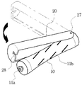
- FIG. 1 is a schematic view showing a permarod according to the present invention as a whole.
- FIG. 2 to 4 is a configuration diagram showing a modification of the permarod according to the present invention.
- Figure 5 is a block diagram showing a state in which a chemical liquid injection portion formed on the rod body.
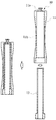
- Figure 6 is a cross-sectional view showing the internal structure of the permarod according to the present invention.
- the present invention relates to permarod, in which permarod prevents the increase of permer cost and environmental pollution due to excessive use of neutralizing agent, and includes hair loss and inflammation caused by neutralizing agent while maximizing neutralizing effect by using neutralizing agent in quantitative amount.
- a rod body 10 for drying the hair and a rod cap 20 for fixing the dried hair to the rod body 10 are provided between the rod body 10 and the rod cap 20.
- the chemical liquid filling part 30 is formed to fill the chemical liquid (neutralizing agent), and the chemical liquid injection part 40 is formed on the rod body 10 or the rod cap 20 to supply the chemical liquid onto the chemical liquid filling part 30. ) Is provided.
- the rod body 10 is formed in a cylindrical shape, the outer circumferential surface is formed so as to shrink in diameter from both side edge portion to the middle portion, it is fixed by the rod cap 20 in the hair wound state.
- the rod cap 20 has a cut-out portion 22 formed on one side of the rod-shaped body 10 in a longitudinal cross-sectional shape "C" shape so as to surround the rod body 10, and the rod body 10 through the cut portion 22. ) The hair wound on) is exposed to the outside.
- FIG. 2 to 4 is a configuration diagram showing a modified example of the rod cap 20
- Figure 2 is a rod cap 20 is the receiving portion 21 to the inside to press the outer peripheral surface of the rod body 10 by the elastic force Is formed, the receiving portion 21 is formed to open to the outside through the incision portion 22 on one side.
- the rod body 10 is wound on the outer circumferential surface of the rod body 10 and presses onto the cutout portion 22 of the rod cap 20, the rod body 10 is temporarily extended while the cutout portion 22 of the rod cap 20 is temporarily expanded. It is received, and then the outer peripheral surface of the rod body 10 is pressed by the elastic force of the rod cap 20 to fix the hair.
- hook groove 15 is formed in a circular recess in the central portion of the rod body 10, the hook 25 is formed in the longitudinal direction of the rod body 10 at one side of the rod cap (20). Accordingly, the hook 25 of the rod cap 20 is matched with the hook groove 15 while the hair is wound on the rod body 10, and then the rod cap 20 is pressed in the longitudinal direction of the rod body 10. The hook 25 and the hook groove 15 are engaged with each other and fixed. On the other hand, in order to prevent the flow of the rod cap 20 coupled to the rod body 10 through the hook 25 and the hook groove 15, it is also possible to include a configuration of the binding portion 28 to be described later on the other end Do.
- the rod cap 20 is provided with a binding portion 28 so that one end is locked / unlocked on the rod body 10 while the rod cap 20 is pivotally pivoted on the hinge 27 on the rod body 10. .
- One end of the rod cap 20 is pivoted by pivoting the hinge 27 at the end side of the rod body 10, the other end is provided with a hook and hook groove one-touch engagement portion 28 is locked / unlocked do.
- an end portion coupled to the hinge of the rod cap 20 may be dividedly formed with the rod body 10 so that the rod body 10 is not disturbed while the hair is wound on the rod body 10. .
- a chemical liquid filling part 30 is formed between the rod body 10 and the rod cap 20 so as to fill the chemical liquid, and is formed on the rod body 10 or the rod cap 20 to fill the chemical liquid filling part ( 30 is provided with a chemical liquid injection unit 40 for supplying the chemical liquid.
- the chemical liquid filling part 30 is a space formed between the rod body 10 and the rod cap 20, the hair is impregnated with the chemical liquid injected through the injection portion 40, as well as the hair impregnated in the chemical liquid It has a structure. And both ends of the rod body 10 and the both ends of the rod cap 20 is formed to be in close contact with the drug solution filled in the drug solution filling portion 30 to both ends of the rod cap 20, the close portion In order to improve the airtightness, the rod body 10 and the rod cap 20 may be provided with the airtight packing 50 provided at both ends thereof.
- the chemical injection portion 40 is formed in the inlet 11a so that the user is supplied to the drug solution by fastening the liquid container in the rod body 10 or the rod cap 20, the injection hole 11a is the flow path (13) In communication with the chemical liquid filling unit 30 is supplied with the chemical liquid.
- the injection rod 11a is formed on one side of the rod body 10 and a plurality of injection holes 11b are formed on the outer circumferential surface thereof.
- An inner tube 12 accommodated in the outer tube 11 and the outer tube 11 and formed between the inner and outer tubes 12 and 11 so as to communicate with the injection hole 11a and the injection hole 11b. 13).
- the exterior 11 is open at one side and the injection hole 11a is formed at the other side, the inner tube 12 is closed at one side, the jaw is formed at the other outer diameter. Accordingly, as shown in FIG. 5, when assembling the inner and outer tubes 12 and 11, one side gap between the inner and outer tubes 12 and 11 is closed by the jaw to form a flow passage 13 communicating with the injection hole 11a. .
- the width of the flow path 13 can be narrowly formed to be 1 mm or less. The waste due to the chemical liquid remaining in the flow path 13 after supplying the chemical liquid is prevented.
- the backflow preventing member (finish plate, rubber stopper) on the inlet (11a) in order to prevent the backflow of the drug solution through the flow path 13 after the filling of the drug solution on the drug solution filling section 30 through the injection port (11a) ) May be further formed.
- the injection hole (11b) is formed in the form of a long hole forming an inclination angle of 5 ⁇ 10 ° relative to the longitudinal direction of the rod body (10). Therefore, due to the inclination angle of the injection hole (11b) is extended to the spray area in the hair wound direction in the rod body 10 there is an advantage that the coating efficiency of the chemical liquid is improved.
- a soft pad 50 is provided on the outer circumferential surface of the rod body 10 or the inner circumferential surface of the rod cap 20.
- the soft pad 50 is flexibly deformed and closely adhered to the outer circumferential surface or the inner circumferential surface of the irregularly wound hair. Since it is not formed, there is an advantage that the chemical liquid penetrates more closely between the hairs while preventing the waste of the chemical liquid due to unnecessary space, thereby improving the neutralization effect.
Landscapes
- Hair Curling (AREA)
Applications Claiming Priority (4)
| Application Number | Priority Date | Filing Date | Title |
|---|---|---|---|
| KR20-2012-0001216 | 2012-02-17 | ||
| KR20120001216 | 2012-02-17 | ||
| KR2020120002154U KR200463574Y1 (ko) | 2012-02-17 | 2012-03-19 | 퍼머롯드 |
| KR20-2012-0002154 | 2012-03-19 |
Publications (1)
| Publication Number | Publication Date |
|---|---|
| WO2013122308A1 true WO2013122308A1 (fr) | 2013-08-22 |
Family
ID=48984400
Family Applications (1)
| Application Number | Title | Priority Date | Filing Date |
|---|---|---|---|
| PCT/KR2012/009333 Ceased WO2013122308A1 (fr) | 2012-02-17 | 2012-11-07 | Cylindre de permanente |
Country Status (1)
| Country | Link |
|---|---|
| WO (1) | WO2013122308A1 (fr) |
Cited By (3)
| Publication number | Priority date | Publication date | Assignee | Title |
|---|---|---|---|---|
| KR101796904B1 (ko) | 2017-09-04 | 2017-11-14 | 박옥남 | 헤어드라이어 노즐악세사리를 구비한 파마용 헤어컬링장치 |
| KR101796903B1 (ko) | 2017-09-04 | 2017-11-14 | 박옥남 | 파마액 및 중화제 공급기능을 구비한 파마로드 |
| KR20190137422A (ko) * | 2018-06-01 | 2019-12-11 | 지장원 | 헤어 보톡스 장치 및 헤어 보톡스 시스템 |
Citations (4)
| Publication number | Priority date | Publication date | Assignee | Title |
|---|---|---|---|---|
| JPS59130601U (ja) * | 1983-02-21 | 1984-09-01 | 瀧川株式会社 | 頭髪用カ−ラ− |
| JPS6371803U (fr) * | 1986-10-28 | 1988-05-13 | ||
| KR200400678Y1 (ko) * | 2005-08-24 | 2005-11-08 | 최충식 | 음이온을 발생시키는 고정구를 갖는 퍼머로드 |
| KR100769716B1 (ko) * | 2007-04-20 | 2007-10-24 | 심국현 | 액상의 기능성 물질이 수납된 퍼머용 롯드 |
-
2012
- 2012-11-07 WO PCT/KR2012/009333 patent/WO2013122308A1/fr not_active Ceased
Patent Citations (4)
| Publication number | Priority date | Publication date | Assignee | Title |
|---|---|---|---|---|
| JPS59130601U (ja) * | 1983-02-21 | 1984-09-01 | 瀧川株式会社 | 頭髪用カ−ラ− |
| JPS6371803U (fr) * | 1986-10-28 | 1988-05-13 | ||
| KR200400678Y1 (ko) * | 2005-08-24 | 2005-11-08 | 최충식 | 음이온을 발생시키는 고정구를 갖는 퍼머로드 |
| KR100769716B1 (ko) * | 2007-04-20 | 2007-10-24 | 심국현 | 액상의 기능성 물질이 수납된 퍼머용 롯드 |
Cited By (4)
| Publication number | Priority date | Publication date | Assignee | Title |
|---|---|---|---|---|
| KR101796904B1 (ko) | 2017-09-04 | 2017-11-14 | 박옥남 | 헤어드라이어 노즐악세사리를 구비한 파마용 헤어컬링장치 |
| KR101796903B1 (ko) | 2017-09-04 | 2017-11-14 | 박옥남 | 파마액 및 중화제 공급기능을 구비한 파마로드 |
| KR20190137422A (ko) * | 2018-06-01 | 2019-12-11 | 지장원 | 헤어 보톡스 장치 및 헤어 보톡스 시스템 |
| KR102089149B1 (ko) * | 2018-06-01 | 2020-03-13 | 지장원 | 헤어 보톡스 장치 및 헤어 보톡스 시스템 |
Similar Documents
| Publication | Publication Date | Title |
|---|---|---|
| US7435029B1 (en) | Liquid application system | |
| WO2016200088A1 (fr) | Serviette absorbante portable pour urine | |
| WO2014181987A1 (fr) | Contenant cosmétique de type à pompage comprenant un bouton latéral | |
| WO2013122308A1 (fr) | Cylindre de permanente | |
| WO2014129767A1 (fr) | Réceptacle sous vide pour produit cosmétique de type crème | |
| WO2010076912A1 (fr) | Contenant à rouleau cosmétique double comprenant une pompe sans air | |
| WO2017043673A1 (fr) | Conteneur à cosmétique de type à pompage et buse fixe | |
| WO2016108405A1 (fr) | Récipient de colorant de type à décharge rotative | |
| WO2015137708A1 (fr) | Contenant en forme de tube du type à ouverture/fermeture rotative | |
| WO2018174374A1 (fr) | Récipient de type tube comportant une partie applicateur détachable | |
| WO2017131357A1 (fr) | Récipient compact | |
| BRPI0518047A (pt) | dispositivo aplicador para aplicar um fluido de multicomponentes | |
| WO2015053551A1 (fr) | Récipient pour produit cosmétique du type à évacuation par rotation | |
| CN209547264U (zh) | 一种AirPods充电盒保护套 | |
| WO2012053814A2 (fr) | Récipient tubulaire jetable doté d'un couvercle intégré | |
| KR200463574Y1 (ko) | 퍼머롯드 | |
| WO2017115990A1 (fr) | Contenant cosmétique de type à pompage ayant un applicateur en métal | |
| WO2017026662A1 (fr) | Récipient compact utilisant un aimant | |
| WO2012046992A2 (fr) | Conteneur pour tube à brosse capable d'être ouvert ou fermé par rotation | |
| CN206988641U (zh) | 一种快速取水装置 | |
| WO2012124975A2 (fr) | Flacon pour cosmétiques de type à pompe impliquant la rotation d'une roue latérale | |
| WO2012091248A1 (fr) | Dispositif de verrouillage de pompe | |
| KR20140050364A (ko) | 퍼머롯드 | |
| US20150059081A1 (en) | Shower partition assembly | |
| WO2014142455A1 (fr) | Récipient pour mélanger différents types de contenus |
Legal Events
| Date | Code | Title | Description |
|---|---|---|---|
| 121 | Ep: the epo has been informed by wipo that ep was designated in this application |
Ref document number: 12868586 Country of ref document: EP Kind code of ref document: A1 |
|
| NENP | Non-entry into the national phase |
Ref country code: DE |
|
| 122 | Ep: pct application non-entry in european phase |
Ref document number: 12868586 Country of ref document: EP Kind code of ref document: A1 |