WO2013124903A1 - Dispositif de type capteur à fonction d'échantillonnage et système de traitement de données de capteur l'utilisant - Google Patents
Dispositif de type capteur à fonction d'échantillonnage et système de traitement de données de capteur l'utilisant Download PDFInfo
- Publication number
- WO2013124903A1 WO2013124903A1 PCT/JP2012/001275 JP2012001275W WO2013124903A1 WO 2013124903 A1 WO2013124903 A1 WO 2013124903A1 JP 2012001275 W JP2012001275 W JP 2012001275W WO 2013124903 A1 WO2013124903 A1 WO 2013124903A1
- Authority
- WO
- WIPO (PCT)
- Prior art keywords
- sensor
- sensor device
- measurement
- count command
- sampling
- Prior art date
- Legal status (The legal status is an assumption and is not a legal conclusion. Google has not performed a legal analysis and makes no representation as to the accuracy of the status listed.)
- Ceased
Links
Images
















Classifications
-
- G—PHYSICS
- G01—MEASURING; TESTING
- G01C—MEASURING DISTANCES, LEVELS OR BEARINGS; SURVEYING; NAVIGATION; GYROSCOPIC INSTRUMENTS; PHOTOGRAMMETRY OR VIDEOGRAMMETRY
- G01C23/00—Combined instruments indicating more than one navigational value, e.g. for aircraft; Combined measuring devices for measuring two or more variables of movement, e.g. distance, speed or acceleration
-
- G—PHYSICS
- G01—MEASURING; TESTING
- G01C—MEASURING DISTANCES, LEVELS OR BEARINGS; SURVEYING; NAVIGATION; GYROSCOPIC INSTRUMENTS; PHOTOGRAMMETRY OR VIDEOGRAMMETRY
- G01C19/00—Gyroscopes; Turn-sensitive devices using vibrating masses; Turn-sensitive devices without moving masses; Measuring angular rate using gyroscopic effects
-
- G—PHYSICS
- G01—MEASURING; TESTING
- G01C—MEASURING DISTANCES, LEVELS OR BEARINGS; SURVEYING; NAVIGATION; GYROSCOPIC INSTRUMENTS; PHOTOGRAMMETRY OR VIDEOGRAMMETRY
- G01C21/00—Navigation; Navigational instruments not provided for in groups G01C1/00 - G01C19/00
- G01C21/10—Navigation; Navigational instruments not provided for in groups G01C1/00 - G01C19/00 by using measurements of speed or acceleration
-
- G—PHYSICS
- G01—MEASURING; TESTING
- G01D—MEASURING NOT SPECIALLY ADAPTED FOR A SPECIFIC VARIABLE; ARRANGEMENTS FOR MEASURING TWO OR MORE VARIABLES NOT COVERED IN A SINGLE OTHER SUBCLASS; TARIFF METERING APPARATUS; MEASURING OR TESTING NOT OTHERWISE PROVIDED FOR
- G01D21/00—Measuring or testing not otherwise provided for
-
- H—ELECTRICITY
- H03—ELECTRONIC CIRCUITRY
- H03K—PULSE TECHNIQUE
- H03K21/00—Details of pulse counters or frequency dividers
- H03K21/02—Input circuits
- H03K21/023—Input circuits comprising pulse shaping or differentiating circuits
-
- H—ELECTRICITY
- H03—ELECTRONIC CIRCUITRY
- H03K—PULSE TECHNIQUE
- H03K21/00—Details of pulse counters or frequency dividers
- H03K21/38—Starting, stopping or resetting the counter
Definitions
- the present invention relates to a sensor device with a sampling function and a sensor data processing system using the same, and more specifically, a measurement number ratio between sensor devices is arbitrarily set and held, and a measurement number ratio between the set sensor devices.
- the present invention relates to a sensor device with a sampling function that can be measured autonomously while maintaining the above and a sensor data processing system using the same.
- the load on the integrated processing unit that acquires and processes the sensor data is reduced. It is also important to avoid unnecessary or inefficient measurements by performing optimal measurement management for each sensor device.
- Patent Document 1 discloses a sensor device that operates autonomously independently of the integrated processing unit in order to reduce the load on the integrated processing unit.
- FIG. 1 is a configuration diagram of a conventional GPS receiver with a DR sensor sampling function, which is a GPS receiver described in Patent Document 1.
- This GPS receiver is equipped not only with a GPS positioning function but also with other functions required as a car navigation system, and can provide information in a form that is easy to use for a CPU (central processing unit).
- 8 is a GPS antenna
- 10 is a CPU
- 12 is a gyro
- 14 and 16 are filters
- 20 is a GPS receiver
- 22 is a control unit
- 24 is an A / D conversion unit
- 26 is a counter
- 100 is a navigation system. ing.
- the GPS receiver described in Patent Document 1 includes a sampling unit that samples DR sensor signals such as a gyro sensor, a vehicle speed pulse, and a back signal at a predetermined period, and a plurality of sampling data sampled by the sampling unit.
- a control means for outputting as one frame of data for each cycle in which the GPS positioning solution is calculated is provided.
- this control means outputs one frame of data as serial data
- the CPU acquires the sampling data of the DR sensor together with the GPS positioning solution only by controlling the serial interface.
- the GPS receiver described in Patent Document 1 is an integrated processing unit realized by a conventional CPU by a sensor device independent of the CPU managing the measurement of each sensor device and collectively transmitting data to the CPU. Reduce processing.
- the GPS receiver that performs measurement at the first frequency (low) has a control unit that manages measurement of each device for DR at the second frequency (high), and collectively transmits to the CPU at the first frequency.
- the main device controls and manages the measurement of each sensor device instead of the CPU, it is possible to perform measurement while synchronizing at a desired frequency without imposing a load on the CPU.
- a specific device having such a function becomes essential, and the sensor device connected to the main device cannot operate autonomously.
- sensor devices As sensor devices that can operate completely autonomously, sensor devices have been developed that have their own clocks inside and that each makes autonomous measurements. Thereby, it is possible to perform measurement autonomously at each frequency at which each sensor device is set without imposing a load on the CPU. However, since it operates with its own clock, there is a problem that the measurement timing is shifted between the sensor devices and synchronization cannot be achieved.
- sensor devices have been developed that perform measurement autonomously by receiving an external trigger to synchronize the measurement timing.
- the magnetic sensor described in Patent Document 2 is a magnetic sensor that can detect a trigger from the outside and perform sampling in synchronization between the detection units (sensors).
- FIG. 2 is a block diagram for explaining the magnetic sensor described in Patent Document 2.
- the magnetic sensor 9 corresponds to the magnetic sensors 9a and 9b, and includes a plurality of magnetic detection units 11a to 11c, sampling processing units 17a to 17c, a trigger detection unit 13, and a hold processing unit 19.
- the detection signals from the plurality of magnetic detection units 11a to 11c are configured to be sampled by the sampling processing units 17a to 17c, respectively.
- the signals sampled by the sampling processing units 17a to 17c are respectively input to the hold processing unit 19, held until the next signal is input, and appropriately output to the outside.
- the sampling processing units 17a to 17c are driven in synchronization with an external trigger signal input to the trigger detection unit 13, and are configured to perform sampling only once.
- the drive circuits for the magnetic sensors 11a to 11b can also be driven in synchronization with the external trigger signal input to the trigger detection unit 13.
- Reference numeral 15 denotes a control unit.
- Patent Document 2 in the case of using a plurality of sensor devices having the same measurement frequency, there is a technique for measuring by synchronizing the measurement timing between the sensor devices.
- the measurement frequency and the measurement timing are also different for power saving / optimization or due to the difference in time required for measurement.
- patent document 3 since the measurement timing between the sensor devices is shifted, when integrating the sensor devices, it is necessary to perform a data shift correction process to associate the data.
- patent document 3 is mentioned.
- the timing of processing between sensor devices is matched by setting and outputting a delay time in accordance with a shift in measurement timing.
- an optimum position is estimated by combining a position calculated from autonomous navigation and a position calculated from GPS (Global Positioning System).
- GPS Global Positioning System
- the current position is calculated by updating the previous positioning position based on the speed pulse indicating the speed of the vehicle and the gyro, that is, the turning angular speed of the vehicle measured by the angular speed sensor.
- the position of the vehicle can be derived by autonomous navigation even in tunnels, underground parking lots and valleys of high-rise buildings where it is difficult to receive radio waves from GPS satellites.
- the navigation device described in Patent Document 3 described above derives the angular velocity of the moving body based on the output value of the angular velocity sensor provided in the moving body and the conversion coefficient from the output value of the angular velocity sensor to the angular velocity.
- the present invention relates to a navigation device.
- the navigation apparatus includes a measurement unit that periodically measures measurement data including at least a direction of movement and a movement speed based on a signal received from a satellite, and the measurement timing of the measurement data is measured by the measurement unit.
- the output timing of the output value of the angular velocity sensor is adjusted so as to match.
- the navigation device adjusts the output timing of the output value of the angular velocity sensor in accordance with the error between the detection timing of the output value of the angular velocity sensor and the measurement timing of the measurement data, thereby detecting the detection timing and the measurement timing. It is a device that can reduce the error of
- the phrase “synchronize” has two viewpoints.
- these two viewpoints are distinguished from each other.
- the synchronization in Patent Documents 2 and 3 described above is based on this point of view. As for the measurement timing, it is not always good to make them coincide with each other accurately in time.
- synchronize the viewpoint of maintaining the ratio of the number of measurements is particularly important. Therefore, in the following description of the present invention, unless otherwise specified, “synchronization” is used in the sense that measurement is performed so that there is no deviation in the ratio of the number of measurements based on the measurement frequency.
- sampling there are two viewpoints in “sampling” in consideration of an oversampling method often used in sensor devices.
- AD conversion sampling 1) sampling at the point where an analog signal is sampled / held at the entrance of the analog-to-digital converter. This is called “AD conversion sampling”. 2) The time-discrete signal sequence of the AD conversion output is then sampled at a time interval different from the AD conversion sampling. This is called “sampling during data collection”.
- sampling during data collection is intended unless otherwise specified.
- AD conversion sampling and sampling at the time of data collection are the same.
- the viewpoint of maintaining the ratio of the number of measurements is important.
- the ratio of the number of measurements is regarded as the ratio of the number of times of “sampling during data collection”.
- FIG. 3 is a configuration diagram of a sensor data processing system that discloses a technology that is a premise of a sensor device with a sampling function according to the present invention and that has a function of a CPU managing measurement timing between a plurality of sensor devices.
- the sensor data processing system includes a sensor device 30 including a plurality of sensor devices 31, 32, and 33, and a CPU 35 that processes measurement data from the sensor device 30.
- the first sensor device 31 that receives an external measurement command includes a detection unit 311, a measurement unit 312 that starts measurement from the detection unit 311 in response to an external measurement start command, and a measurement result of the measurement unit 312. And a measurement result holding unit 313 that sends the measurement data to the CPU 35.
- the other second sensor device 32 and the third sensor device 33 also have the same configuration as the first sensor device 31.
- the first sensor device 31 starts measurement.
- the CPU 35 reads out the measurement result held in the measurement result holding unit 313 of the first sensor device 31 as measurement data.
- the second sensor device 32 starts measurement.
- the CPU 35 reads measurement data from the second sensor device 32.
- the third sensor device 33 starts measurement.
- the CPU 35 reads measurement data from the third sensor device 33. In this way, the measurement data from the plurality of sensor devices 31, 32, 33 is processed by the CPU 35.
- the timing of accessing each sensor device is managed based on the measurement frequency.
- the system in which the CPU manages the measurement timings of a plurality of sensor devices is measured on the sensor device side in response to an external command, and the measurement timing is set at the measurement frequency set for each sensor device on the CPU side.
- This is a system for managing data and accessing each sensor device at any time to acquire data. For this reason, there is a problem that the load on the CPU in charge of all the functions of the integrated processing unit is heavy. Therefore, although the problems 1) and 2) described above can be solved, the problem 3) cannot be solved.
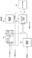
- FIG. 4 discloses a technology that is a premise of a sensor device with a sampling function according to the present invention, and includes a sensor device that does not need to manage measurement timing by a CPU and that independently measures with a clock. It is a block diagram of an autonomous measurement management system.
- the autonomous measurement management system includes a sensor device 40 including a plurality of sensor devices 41, 42, and 43, and a CPU 45 that processes measurement data from the sensor device 40.
- the first sensor device 41 that starts measurement based on its own clock includes a clock generation unit 414, a counter 415 that counts clocks from the clock generation unit 414, a set value by the register setting unit 417, and a counter 415. And a comparison unit 416 that compares the count value.
- the sensor device 41 receives a measurement start command generation unit 418 that generates a measurement start command based on the comparison value from the comparison unit 416, and a measurement start command from the measurement start command generation unit 418.
- a measurement result holding unit 413 that holds the measurement results (including measurement completion notification) of the measurement unit 412 and sends the measurement data to the CPU 45.
- Other second sensor devices 42 and third sensor devices 43 have the same configuration as the first sensor device 41.
- each of the sensor devices 41, 42, and 43 performs a self-running measurement, and generates an interrupt signal when a desired number of measurements are completed.
- the CPU 45 acquires measurement data based on interrupt signals from the sensor devices 41, 42, 43.
- an autonomous measurement management system including a sensor device in which each sensor device independently has a clock and performs measurement autonomously performs measurement based on its own clock on the sensor device side, and performs a desired measurement. It was a system that generated an interrupt signal when the number of measurements was completed.
- the autonomous measurement management system is a system that acquires measurement data by accessing each sensor device based on an interrupt signal from the sensor device on the CPU side. In this case, since each sensor device is responsible for many of the functions of the integrated processing unit, there is an effect that the load on the CPU is reduced. It is also possible for each sensor device to set and measure an optimum measurement frequency.
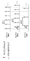
- FIG. 5 is an explanatory diagram of the case where the measurement cycles do not match even if the same sensor device is set to the same measurement frequency because the clocks of the sensor devices vary. For example, when measurement is performed at a measurement frequency of 100 Hz using a clock of 1 kHz that operates with an error of ⁇ 1% ( ⁇ 10 ⁇ sec), it is shifted by ⁇ 10 msec per second, that is, by one measurement count. This deviation is integrated and increased with time. Therefore, although the problems 1) and 3) described above can be solved, the problem 2) cannot be solved.
- the present invention has been made in view of such problems, and an object of the present invention is to arbitrarily set and maintain a measurement number ratio between sensor devices, and autonomously while maintaining the set measurement number ratio between sensor devices.
- An object of the present invention is to provide a sensor device with a sampling function and a sensor data processing system using the same.
- the invention according to claim 1 is a sensor device with a sampling function for maintaining a measurement number ratio between a plurality of sensor devices for measurement. From the counter that counts the count command, the measurement number ratio holding means that holds the setting value of the desired measurement number ratio, the counter value of the counter, and the setting value of the measurement number ratio that is held by the measurement number ratio holding means, Sampling timing generation means for generating a sampling timing signal based on the comparison result between the counter value and the set value, and sampling for starting detection of various information detection signals detected by the detection unit based on the sampling timing signal by the sampling timing generation means And a section.
- a desired measurement start delay time is held in the sampling timing generation means in order to delay the start of sampling of the sampling unit by the sampling timing signal.
- the delay time holding means is connected.
- the detection unit operation start time information holding unit for holding the detection unit operation start time information is provided, and the detection unit operation start time information holding unit is provided.
- the detection unit operation start time information and the detection unit operation control means for inputting the counter value from the counter are provided.
- a count instruction generating means for generating a count instruction, and when the count instruction generated by the count instruction generating means is used, a counter is provided.
- the count command can be output to the outside at the same time as the count command is input.
- the interface for outputting the count command generated by the count command generation means to the outside, and the interface for inputting the count command from the outside Is a single interface.
- the interface for outputting the count command generated by the count command generating means to the outside, and the interface for inputting the count command from the outside Is a single interface and an I2C bus.
- an interface for outputting a count instruction generated by the count instruction generation means to the outside and an interface for inputting a count instruction from the outside. Is a single interface and an SPI bus.
- the operation mode can be switched.
- the invention described in claim 9 is a sensor data processing system using a sensor device with a sampling function, wherein the sensor device according to any one of claims 1 to 8 and a sensor data processing unit are combined to provide sensor data.
- the processing unit has a function of setting a measurement number ratio, transmitting information on the measurement number ratio and a count command to each sensor device, and receiving data from each sensor device.
- the invention described in claim 10 is a sensor data processing system using a sensor device with a sampling function, wherein the sensor device according to any one of claims 1 to 8 is combined with a sensor data processing unit,
- the master device connected to the data processing unit has the function of setting the measurement number ratio, transmitting the measurement number ratio information and the count command to each sensor device, and receiving the data from each sensor device.
- the invention according to claim 11 is a sensor data processing system using a sensor device with a sampling function, wherein the sensor device according to any one of claims 1 to 8 is combined with a sensor data processing unit,
- the data processing unit has a function to set the measurement number ratio, etc., and to send information on the measurement number ratio to each sensor device and a function to receive data from each sensor device. It is characterized by generating and outputting.
- a twelfth aspect of the present invention is a sensor data processing system using a sensor device with a sampling function, wherein the sensor device according to any one of the first to eighth aspects is combined with a sensor data processing unit, and counting is performed.
- An external periodic signal generating means for generating an instruction is provided, a count command is transmitted from the periodic signal generating means to each sensor device, a sensor data processing unit sets a measurement number ratio, and information on the measurement number ratio is transmitted to each sensor. It has the function to transmit to a device, and the function to receive data from each sensor device, It is characterized by the above-mentioned.
- a thirteenth aspect of the present invention is a sensor data processing system using a sensor device with a sampling function, wherein the sensor device according to any one of the first to eighth aspects is combined with a sensor data processing unit, and counting is performed.
- An external periodic signal generation unit that generates an instruction is provided, a count command is transmitted from the periodic signal generation unit to each sensor device, each sensor device and the sensor data processing unit receive, and each sensor device is set by the count command.
- the sensor data processing unit counts the received count command autonomously at a measurement number ratio, and acquires data from each corresponding sensor device when the set number of times is reached.
- a sensor device with a sampling function that can arbitrarily set and maintain a measurement number ratio among a plurality of sensor devices and can autonomously measure while maintaining the measurement number ratio between the set sensor devices, and A sensor data processing system using the same can be provided.
- FIG. 1 is a configuration diagram of a conventional GPS receiver with a DR sensor sampling function.
- FIG. 2 is a block diagram for explaining the magnetic sensor described in Patent Document 2.
- FIG. 3 is a configuration diagram of a measurement timing management system that discloses a technology that is a premise of a signal synchronization apparatus between a plurality of sensor devices according to the present invention, and in which a CPU manages measurement timings between the plurality of sensor devices.
- FIG. 4 discloses a technology which is a premise of a signal synchronization apparatus between a plurality of sensor devices according to the present invention, and a sensor device that autonomously measures with a clock independently, without the CPU managing the measurement timing. It is a block diagram of the autonomous measurement management system provided with. In FIG.
- FIG. 6 is a configuration diagram for explaining Example 1 of the sensor device with a sampling function according to the present invention.
- FIG. 7 is a diagram for explaining the flow of signals at various parts in the configuration diagram shown in FIG.
- FIG. 8 is a diagram showing signals at various parts in FIG.
- FIG. 9 is an explanatory diagram of a signal synchronizer that can autonomously measure among a plurality of sensor devices while maintaining the set measurement number ratio between the sensor devices.
- FIG. 10 is an explanatory diagram when each sensor device has a clock of the same frequency.
- FIG. 11 is a configuration diagram for explaining Example 2 of the sensor device with a sampling function according to the present invention.
- FIG. 12 is a diagram for explaining the flow of signals in each part in the configuration diagram shown in FIG. 11.
- FIG. 13 is a diagram showing signals at various parts in FIG.
- FIG. 14 is an explanatory diagram when the delay time of the measurement start time between the plurality of sensor devices can be set and held.
- FIG. 15 is a configuration diagram for explaining Example 3 of the sensor device with a sampling function according to the present invention.
- FIG. 16 is a diagram for explaining the flow of signals at various parts in the configuration diagram shown in FIG.
- FIG. 17 is a diagram showing signals at various parts in FIG. FIG.
- FIG. 18A shows that the measurement number ratio between the sensor devices in the third embodiment of the sensor device with a sampling function according to the present invention can be arbitrarily set and held, and the operation start time and end time of each detector are also set as delay times. It is explanatory drawing at the time of enabling it to hold
- FIG. 18B shows that the measurement number ratio between the sensor devices in Example 3 of the sensor device with a sampling function according to the present invention can be arbitrarily set and held, and the operation start time and end time of each detection unit are also set as delay times. It is explanatory drawing at the time of enabling it to hold
- FIG. 19 is a block diagram for explaining Example 4 of the sensor device with a sampling function according to the present invention.
- FIG. 20 is a block diagram for explaining a modification of the fourth embodiment of the sensor device with a sampling function according to the present invention.
- FIG. 21 is a configuration diagram for explaining a further modification of the embodiment 4 of the sensor device with a sampling function according to the present invention.
- FIG. 22 shows a sensor data processing system in which the measurement number ratio between the sensor devices shown in FIG. 19 can be arbitrarily set and held, and measurement can be performed autonomously while maintaining the set measurement number ratio between the sensor devices. It is a block diagram.
- FIG. 23 shows sensor data that can arbitrarily set and maintain the measurement number ratio between the sensor devices shown in FIG. 20 and FIG.
- FIG. 24A is a system configuration diagram showing various connection relationships between sensor devices having the configuration shown in FIG. 24B is a system configuration diagram showing various connection relationships between sensor devices having the configuration shown in FIG. 24C is a system configuration diagram showing various connection relationships between sensor devices having the configuration shown in FIG.
- FIG. 24D is a system configuration diagram illustrating various connection relationships between sensor devices having the configuration illustrated in FIG. 21.
- FIG. 24E is a system configuration diagram showing various connection relationships between sensor devices having the configuration shown in FIG.
- FIG. 24F is a system configuration diagram illustrating various connection relationships between sensor devices having the configuration illustrated in FIG. 21.
- FIG. 24A is a system configuration diagram showing various connection relationships between sensor devices having the configuration shown in FIG. 24B is a system configuration diagram showing various connection relationships between sensor devices having the configuration shown in FIG. 24C is a system configuration diagram showing various connection relationships between sensor devices having the configuration shown in FIG.
- FIG. 24D is a system configuration diagram illustrating various connection relationships between sensor devices having the configuration illustrated in FIG. 21.
- FIG. 25 is a block diagram for explaining a sensor data processing system using a plurality of sensor devices according to the fifth embodiment of the present invention.
- FIG. 26 is a system configuration diagram for explaining operations in the block diagram shown in FIG. 25, and is a system configuration diagram when an I2C bus is used for a single count instruction input / output interface.
- FIG. 27 is a system configuration diagram for explaining operations in the block diagram shown in FIG. 25, and is a system configuration diagram when an SPI bus is used for a single count instruction input / output interface.
- FIG. 28 is a block diagram for explaining a sensor data processing system using a plurality of sensor devices according to the sixth embodiment of the present invention.
- FIG. 26 is a system configuration diagram for explaining operations in the block diagram shown in FIG. 25, and is a system configuration diagram when an I2C bus is used for a single count instruction input / output interface.
- FIG. 27 is a system configuration diagram for explaining operations in the block diagram shown in FIG. 25, and is a system configuration diagram when an SPI bus
- FIG. 29 is a block diagram for explaining a sensor data processing system using a plurality of sensor devices according to the seventh embodiment of the present invention.
- FIG. 30 is a block diagram for explaining a sensor data processing system using a plurality of sensor devices according to the eighth embodiment of the present invention.
- FIG. 31 is a block diagram for explaining a sensor data processing system using a plurality of sensor devices according to the ninth embodiment of the present invention.
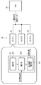
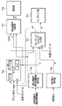
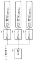
- FIG. 6 is a block diagram for explaining a first embodiment of a sensor device with a sampling function according to the present invention, in which reference numeral 51 is a sensor device, 511 is a counter, 512 is a measurement number ratio holding unit, and 513 is a sampling timing. A generation unit 514, a detection unit 515, and a sampling unit 515.
- the sensor device 51 corresponds to the sensor devices 31, 32, and 33 in FIG. 3, and also corresponds to the sensor devices 41, 42, and 43 in FIG. In FIG. 6, only one sensor device is shown.
- the sensor device 51 sets a counter 511 that counts a count command for measurement while maintaining a measurement number ratio among a plurality of sensor devices, and sets the measurement number ratio to a desired measurement number ratio.
- the measurement number ratio holding unit 512 holds the set value of the measurement number ratio so that the plurality of sensor devices correspond to each other.
- the sensor device 51 receives the counter value of the counter 511 and the set value of the measurement number ratio held by the measurement number ratio holding unit 512, and generates a sampling timing signal after the counter value matches the set value.
- a generation unit 513 and a sampling unit 515 that samples a detection signal detected by the detection unit 514 using a sampling timing signal from the sampling timing generation unit 513 are configured. Measurement data from the sensor device 51 is sent to a CPU (not shown) for signal processing.
- FIG. 7 is a diagram for explaining a signal flow of each part in the configuration diagram shown in FIG.
- FIG. 8 is a diagram showing signals at various parts in FIG.
- FIG. 8 shows an example in which a plurality of sensor devices (sensor1, sensor2, sensor3) are included.
- two signals (rstn, trg) shown in the uppermost stage are signals input from the outside in common to all sensor devices.
- the four signals (clk, trg_sync, trg_count, smpl_org) shown below the partition lines labeled sensor1, sensor2, and sensor3 are internal signals that each sensor device holds independently.
- Trg is the same as trg in the uppermost stage
- smpl1 to 3 are the same as the smpl_org of the sensor devices sensor1 to sensor3.
- Each sensor device operates with an internal clock (clk) of 1 KHz having ⁇ 10% accuracy independent of each other. Moreover, the values of 1, 2, 3 are held as the measurement number ratio (s2). Further, a common count command (trg) of 100 Hz is input. In this example, the count command is realized as a 1-bit signal.
- Each sensor device takes a count command at each internal clock and generates an internal count command (trg_sync) that is active for one clock cycle. Further, each time the internal count instruction becomes active, the count instruction counter value (trg_count, s1) is incremented by one.
- the count command counter When the value of the count command counter coincides with the value ⁇ 1 of the measurement number ratio (s2), it is reset to 0 by the count command counter reset signal (s3).
- the internal basic sampling signal (smpl_org) becomes active for one clock cycle, and this signal is the sampling signal (s4) output from the sampling timing generation unit 513. It becomes.
- the measurement number ratio among a plurality of sensor devices can be arbitrarily set, and the measurement can be performed autonomously while maintaining the set measurement number ratio between the sensor devices.
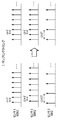
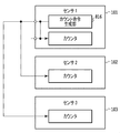
- FIG. 10 is an explanatory diagram in the case where each sensor device has a clock of the same frequency, and is a diagram further explaining the operation of the first embodiment using a more simplified diagram.
- the time at which each sensor device is activated varies, and the clock cycle also varies.
- the measurement number ratio of the first to third sensor devices is 1, 1 and 2
- the measurement cycle t1 is set to T in the first sensor device
- the measurement periods t2 and t3 are set to T and 2T, respectively.
- the measurement cycle is shifted due to the variation in the frequency of the clock, so that it does not accurately become T and 2T, respectively.
- the measurement timing is also shifted. This situation is shown on the left side of FIG. Even in such a situation, if processing is performed through the configuration shown in FIG. 6, measurement can be performed while maintaining the measurement periods T and 2T, respectively, as shown on the right side of FIG.
- the number ratio never shifts. It is also possible to match the measurement timing between the sensor devices.
- the measurement number ratio between the plurality of sensor devices can be arbitrarily set and maintained, and the set measurement number ratio between the sensor devices is maintained. Measurement can be performed autonomously.
- the measurement timing in addition to performing measurement while maintaining the measurement number ratio between the sensor devices, the measurement timing also matches within the range of variation of the clock of each sensor device.
- the measurement timing is intentionally shifted between the sensor devices, and it is important that the delay of the measurement timing can also be set.
- FIG. 11 is a configuration diagram for explaining a second embodiment of the sensor device with a sampling function according to the present invention, and is a configuration diagram of the sensor device that can set and hold the delay time of the measurement start time of each detection unit. is there.
- reference numeral 61 denotes a sensor device, 611 a counter, 612 a measurement number ratio holding unit, 613 a sampling timing generation unit, 614 a detection unit, 615 a sampling unit, and 616 a delay time holding unit.
- the sensor device 61 includes a counter 611 that counts a count command for measurement while maintaining the measurement number ratio among a plurality of sensor devices, and sets the measurement number ratio to a desired measurement number ratio.
- the measurement number ratio holding unit 612 holds a set value of the measurement number ratio so that a plurality of sensor devices correspond to each other. Further, the sensor device 61 inputs the counter value of the counter 611 and the set value of the measured number ratio held by the measured number ratio holding unit 612, and sets the sampling timing signal as a delay time starting from the coincidence of the counter value and the set value.
- a sampling timing generation unit 613 generated after the delay time by the holding unit 616 elapses, and a sampling unit 615 that samples the detection signal detected by the detection unit 614 with the sampling timing signal by the sampling timing generation unit 613.
- a delay time holding unit 616 that holds a desired measurement start delay time is connected to the sampling timing generation unit 613. Measurement data from the sensor device 61 is sent to a CPU (not shown) for signal processing.
- a delay time holding unit 616 that holds a desired delay time;
- the sampling timing generation unit 613 generates a sampling start timing after the delay time has elapsed based on the counter value and the held measurement number ratio.
- FIG. 12 is a diagram for explaining the flow of signals in each part in the configuration diagram shown in FIG.
- FIG. 13 is a diagram showing signals at various parts in FIG.
- FIG. 13 shows an example in which a plurality of sensor devices (sensor1, sensor2, sensor3) are included.
- the two signals (rstn, trg) shown at the uppermost stage are signals input from the outside in common to all sensor devices.
- six signals (from clk to smpl_trg_dly) shown below the partition lines labeled sensor1, sensor2, and sensor3 are internal signals that are independently held by each sensor device.
- the four signals (trg, smpl1, smpl2, and smpl3) shown below the partition lines labeled sensor1,2,3 are signals shown above for easy understanding of the state of synchronization among a plurality of sensor devices.
- trg is the same as trg in the uppermost stage
- smpl1 to 3 are the same as smpl_trg_dly of the sensor devices sensor1 to sensor3.
- Each sensor device operates with an internal clock (clk) of 1 KHz having ⁇ 10% accuracy independent of each other. Moreover, the values of 5, 5, and 5 are held as the measurement number ratio (s2), respectively.
- the delay time information (a1, a2) is information for determining the final sampling timing, and is specified as a delay time from the internal basic sampling signal (smpl_org).
- the delay time (a1) is a value indicating how many count instructions are delayed from the internal basic sampling signal
- the delay time (a2) is how many more clocks after being delayed by a1 count instructions. This is a value indicating whether to sample with a delay.
- a1 holds values of 0, 1, 2 and a2 holds values of 0, 0, 0 (0 operates without delay).
- a common count command (trg) of 100 Hz is input. In this example, the count command is realized as a 1-bit signal.
- Each sensor device takes in a count command at each internal clock and generates an internal count command (trg_sync) that is active for one clock cycle. Further, each time the internal count instruction becomes active, the count instruction counter value (trg_count, s1) is incremented by one. When the value of the count command counter coincides with the value ⁇ 1 of the measurement number ratio (s2), it is reset to 0 by the count command counter reset signal (s3). When the internal count command becomes active while the count command counter is reset, the internal basic sampling signal (smpl_org) becomes active for one clock cycle.
- a sampling signal (output from the sampling timing generation unit 613) is a signal that becomes active for one clock cycle from the timing when the a1st internal count command becomes active from the timing when this signal becomes active to the timing when the clock operates a2 times. smpl_trg_dly, s4).
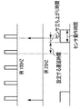
- FIG. 14 is an explanatory diagram when the delay time of the measurement start time between a plurality of sensor devices can be set and held.
- the ratio of the number of measurements between sensor devices can be set and held arbitrarily, and the delay time of the measurement start time of each sensor device can also be set and held. This is useful when it is desired to shift the sampling time little by little so that the sensors do not interfere with each other. Moreover, it can measure autonomously, maintaining the measurement number ratio between the set sensor devices.
- FIG. 15 is a block diagram for explaining a third embodiment of the sensor device with a sampling function according to the present invention.
- the first embodiment shown in FIG. 6 includes a detection unit operation start time information holding unit and a detection unit operation control unit. It is the block diagram which added.
- reference numeral 71 denotes a sensor device, 711 a counter, 712 a measurement number ratio holding unit, 713 a sampling timing generation unit, 714 a detection unit, 715 a sampling unit, 716 a detection unit operation start time information holding unit, and 717
- movement control part is shown.
- the sensor device 71 includes a counter 711 that counts a count command for measurement while maintaining the measurement number ratio among a plurality of sensor devices, and sets the measurement number ratio to a desired measurement number ratio.
- a measurement number ratio holding unit 712 that holds a set value of the measurement number ratio so that a plurality of sensor devices correspond to each other; a detection unit operation start time information holding unit 716 that holds desired detection unit operation start time information; It consists of
- the sensor device 71 includes a detection unit operation control unit 717 that controls the operation of the detection unit 714 based on the counter value from the counter 711 and the detection unit operation start time information from the detection unit operation start time information holding unit 716.
- a sampling timing generation unit 713 that inputs a counter value of the counter 711 and a setting value of the measurement number ratio held by the measurement number ratio holding unit 712 and generates a sampling timing signal after the counter value matches the setting value, and a detection unit And a sampling unit 715 that samples the detection signal detected in 714 with the sampling timing signal from the sampling timing generation unit 713.
- Measurement data from the sensor device 71 is sent to a CPU (not shown) for signal processing.
- FIG. 16 is a diagram for explaining a signal flow of each part in the configuration diagram shown in FIG.
- FIG. 17 is a diagram showing signals at various parts in FIG.
- FIG. 17 shows an example in which a plurality of sensor devices (sensor1, sensor2, sensor3) are included.
- two signals (rstn, trg) shown at the uppermost stage are signals input from the outside in common to all sensor devices.
- four (from clk to smpl_org) or five (from clk to power_enable) signals shown below each of the partition lines labeled sensor1, sensor2, and sensor3 are internal signals held independently by each sensor device. is there.
- the six signals (from trg to smpl3) shown below the partition lines labeled sensors 1, 2, and 3 are for easy understanding of the synchronization between a plurality of sensor devices and the operation of the detection unit of each sensor device.
- the signal shown above was reprinted.
- trg is the same as trg in the uppermost stage
- smpl1 to 3 are the same as the smpl_org of the sensor devices sensor1 to sensor3
- power_enable2 and 3 are the same as the power_enable of the sensor devices sensor2 and sensor3.
- the detection unit operation start time information (a1, a2) is information for determining the detection unit operation start time, and is specified as a delay time from the internal basic sampling signal (smpl_org, s4).
- the delay time (a1) is a value indicating how many count instructions are delayed from the internal basic sampling signal
- the delay time (a2) is how many clock delays after being delayed by a1 count instructions. It is a value indicating whether to do.
- a1 holds values of 0, 1, 2 and a2 holds values of 0, 0, 0, respectively.
- a common count command (trg) of 100 Hz is input.
- the count command is realized as a 1-bit signal.
- Each sensor device takes in a count command at each internal clock and generates an internal count command (trg_sync) that is active for one clock cycle. Further, each time the internal count instruction becomes active, the count instruction counter value (trg_count, s1) is incremented by one. When the value of the count command counter coincides with the value ⁇ 1 of the measurement number ratio (s2), it is reset to 0 by the count command counter reset signal (s3). When the internal count command becomes active while the count command counter is reset, the internal basic sampling signal (smpl_org) becomes active for one clock cycle. This signal becomes the sampling signal (s4) which is the output of the sampling timing generation unit 713.
- the detection unit operation control unit 717 detects the timing at which the clock has been operated a2 times from the timing at which the a1st internal count command is activated from the timing at which the sampling signal is activated, and the operation of the detection unit 714 is started. Then, at the end of the next sampling (for example, the falling edge of the sampling signal), the detection unit 714 is paused and waits until the next operation start timing.
- FIG. 18A and 18B can arbitrarily set and hold the measurement number ratio between the sensor devices in the third embodiment of the sensor device with a sampling function according to the present invention, and the operation start time and end time of each detection unit are also delay times.
- FIG. 18A shows a case where the measurement number ratio is 1
- FIG. 18B shows a case where the measurement number ratio is 4.
- FIG. 19 is a block diagram for explaining a fourth embodiment of the sensor device with a sampling function according to the present invention, and is a block diagram in which a count command generator is added to the counter of the first embodiment shown in FIG.
- 81 is a sensor device
- 811 is a counter
- 812 is a measurement number ratio holding unit
- 813 is a sampling timing generation unit
- 814 is a detection unit
- 815 is a sampling unit
- 816 is a count command generation unit
- 817 is a count command output control.
- SW1 is a sensor device
- 811 is a counter
- 812 is a measurement number ratio holding unit
- 813 is a sampling timing generation unit
- 814 is a detection unit
- 815 is a sampling unit
- 816 is a count command generation unit
- 817 is a count command output control. Part (SW1).
- the sensor device 81 includes a counter 811 that counts a count command for performing measurement while maintaining a measurement number ratio among a plurality of sensor devices, and a count command generation unit 816 that generates a count command.
- the count command output control unit 817 controls whether to use the generated count command as a count command for synchronization between sensor devices.
- the sensor device 81 includes a measurement number ratio holding unit 812 that sets a measurement number ratio to a desired measurement number ratio and holds a set value of the measurement number ratio so that a plurality of sensor devices correspond to each other, and a counter of the counter 811
- a sampling timing generation unit 813 that inputs a value and a setting value of the measurement number ratio held by the measurement number ratio holding unit 812 and generates a sampling timing signal after the counter value matches the setting value, and is detected by the detection unit 814.
- the sampling unit 815 samples the detected signal with the sampling timing signal from the sampling timing generation unit 813. Measurement data from the sensor device 81 is sent to a CPU (not shown) for signal processing.
- a count command output control unit (SW1) 817 is provided between the count command output terminal and the count command generation unit 816. The count command input terminal and the line of the counter 811, and the count command output terminal and the count command generation unit 816 Lines are connected.
- FIG. 20 is a block diagram for explaining a modification of the sensor device with a sampling function according to the fourth embodiment of the present invention, in which a count command generation unit is added to the counter of the first embodiment shown in FIG. is there.
- a count command input terminal and a count command output terminal are provided.
- the count command output control unit (SW1) 817 It is provided between the generation unit 816. That is, it is a configuration diagram in which the counter command output and the count command input interface shown in FIG. 19 are shared.
- the sensor device can perform two operations in order to perform measurement while maintaining the measurement number ratio among a plurality of sensor devices.
- the count command generated from the internal count command generator can be input to the counter and simultaneously output to the outside.
- the direction of the count instruction input / output interface is an instruction output.
- the sensor devices operate synchronously according to the external master (SW1 is OFF)
- a count command input from the outside through the count command input / output interface is input to the counter.
- the direction of the count instruction input / output interface is an instruction input.
- the interface for outputting the count command generated by the count command generator 816 to the outside and the interface for inputting the count command from the outside are a single interface.
- Such a configuration makes it possible to easily realize the same function as compared with the configuration shown in FIG. 19 without dividing the interface of the sensor device for input and output. Thereby, not only the configuration of each sensor device is simplified, but also the effect of further simplifying the configuration of the entire sensor data processing system can be obtained.
- FIG. 21 is a block diagram for explaining a further modification of the sensor device with a sampling function according to the fourth embodiment of the present invention, in which a counter command generator is added to the counter of the first embodiment shown in FIG. FIG. As in FIG. 20, only the count command input / output terminal is provided, but SW2 is provided between the count command input / output terminal and the counter. That is, the counter instruction input / output interface of the embodiment shown in FIG. 20 can be disconnected from the internal count instruction generation unit 816 and the counter 811.
- the sensor device can realize three operations in order to perform measurement while maintaining the measurement number ratio among a plurality of sensor devices.
- the count command generated from the internal count command generator 816 is input to the counter 811 and at the same time externally. Can output.
- the direction of the count instruction input / output interface is an instruction output.
- the sensor devices operate in synchronization with each other according to the external master (SW1 is OFF and SW2 is ON)
- a count command input from the outside through the count command input / output interface is input to the counter 811.
- the direction of the count instruction input / output interface is an instruction input.
- the count command generated from the internal count command generator 816 is input to the counter 811. This command is not output to the outside. In this case, the count command input / output interface is disconnected from the internal count command generation unit 816 and the counter 811.
- the interface for outputting the count instruction generated by the count instruction generation unit 816 to the outside and the interface for inputting the count instruction from the outside may be a single interface and an I2C bus.
- I2C is a serial bus used for embedded systems and mobile phones, and is an abbreviation of “Inter-Integrated Circuit”. It is generally written as I2C and is called “I-To-Sea”. A data processing system using an I2C bus is shown in FIG.
- the interface for outputting the count instruction generated by the count instruction generation unit 816 to the outside and the interface for inputting the count instruction from the outside can be a single interface and can be an SPI bus.
- This "SPI" is a serial peripheral interface (Serial Peripheral Interface), which is a bus that connects devices used inside a computer.
- a data processing system using the SPIC bus is shown in FIG. 27 described later.
- FIG. 22 shows a sensor data processing system in which the measurement number ratio between the sensor devices shown in FIG. 19 can be arbitrarily set and held, and measurement can be performed autonomously while maintaining the set measurement number ratio between the sensor devices.
- the block diagram the relationship between a plurality of sensor devices 101, 102, 103 having a count command input terminal and a count command output terminal is shown.
- FIG. 23 shows sensor data that can arbitrarily set and maintain the measurement number ratio between the sensor devices shown in FIG. 20 and FIG. 21, and can autonomously measure while maintaining the set measurement number ratio between the sensor devices.
- the block diagram of the processing system shows the relationship between a plurality of sensor devices 101, 102, and 103 having only count command input / output terminals.
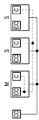
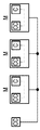
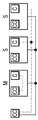
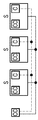
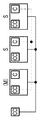
- 24A to 24F are system configuration diagrams showing various connection relationships between sensor devices having the configuration shown in FIG. 21, where CC is a count command generation unit, C is a counter, M is a master, and S is a slave. Show. Of the wirings in the figure, the solid line indicates the physical connection between the sensor devices, and the broken line indicates the final connection between the count command generator and the counter realized by switching the operation mode of each sensor device. , Respectively. As is apparent from FIGS. 24A to 24F, a plurality of master-slave configurations can be realized by switching the operation mode of each sensor device even when the physical connection between the sensor devices is fixed.
- a sensor device with a sampling function that can arbitrarily set and maintain a measurement number ratio among a plurality of sensor devices and can autonomously measure while maintaining the set measurement number ratio between sensor devices is provided. be able to.
- FIGS. 25 to 31 are block diagrams for explaining a sensor data processing system in the case of using the above-described plurality of sensor devices of the present invention.
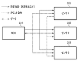
- FIG. 25 is a block diagram for explaining a data processing system when the sensor device according to the fifth embodiment of the present invention is used.
- reference numerals 101 to 103 denote sensor devices
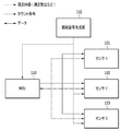
- 110 denotes an MCU (sensor data processing unit).
- the solid line indicates the setting content such as the measurement number ratio and other commands
- the broken line indicates the count command
- the alternate long and short dash line indicates the data.
- the MCU Micro Controller Unit; microcontroller
- the MCU is an embedded microprocessor in which a computer system is integrated into one integrated circuit. Mainly used for controlling electronic equipment.
- the MCU itself has many peripheral functions such as memories such as ROM and RAM, and I / O related functions. For this reason, compared with the case where ROM etc. are mounted as an independent component, the cost for system construction can be held down. In the present invention, it functions as a sensor data processing unit.
- the fifth embodiment is composed of sensor devices 101, 102, and 103 having the functions of the present invention, and an MCU 110 to which the sensor devices 101, 102, and 103 are connected.
- the MCU 110 sets a measurement number ratio and the like, transmits the information to the sensor devices 101, 102, and 103, generates a count command, and transmits the information to the sensor devices 101, 102, and 103.
- FIG. 26 is a system configuration diagram for explaining the operation in the block diagram shown in FIG. 25, and is a system configuration diagram when an I2C bus is used for a single count instruction input / output interface.
- Each sensor device 101, 102, 103 and MCU 110 have an I2C interface and communicate with each other by I2C.
- the measurement ratio is set by the MCU 110 and transmitted to each sensor device 101, 102, 103.
- Each sensor device 101, 102, 103 has a broadcast address in addition to a unique address, and each sensor device 101, 102, 103 simultaneously receives the count command transmitted from the MCU 110 using the broadcast address.
- each of the sensor devices 101, 102, 103 performs measurement autonomously at the set measurement number ratio, and sets an interrupt flag when the measurement is completed.
- the MCU 110 detects an interrupt flag indicating the end of measurement, the MCU 110 retrieves data.
- FIG. 28 is a block diagram for explaining a sensor data processing system when a plurality of sensor devices according to Embodiment 6 of the present invention are used.
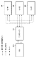
- each sensor device 101, 102, 103 having the function of the present invention a master device 111 to which each sensor device 101, 102, 103 is connected, data can be transmitted to and received from this master device 111, and the number of measurements It is comprised with MCU110 which can set ratio etc.
- the master device 111 has a function of transmitting information such as a measurement number ratio obtained from the MCU 110 to each of the sensor devices 101, 102, 103, a function of generating a count command and transmitting it to each of the sensor devices 101, 102, 103, It has a function of receiving data from the sensor devices 101, 102, and 103 and a function of transmitting and receiving data to and from the MCU 110.
- FIG. 29 is a block diagram for explaining a sensor data processing system when a plurality of sensor devices according to Embodiment 7 of the present invention are used.
- the seventh embodiment includes each sensor device 101, 102, 103 having the function of the present invention and an MCU 110 to which the sensor devices 101, 102, 103 are connected.
- This MCU 110 has a function of setting a measurement number ratio and the like and transmitting the information to each of the sensor devices 101, 102, and 103, and a function of receiving data from each of the sensor devices 101, 102, and 103. It does not have the function to generate.
- One of the sensor devices generates and outputs a count command.
- FIG. 26 is a system configuration diagram for explaining the operation in the block diagram shown in FIG. 29, and is a system configuration diagram when an I2C bus is used for a single count instruction input / output interface.
- each sensor device has a common slave address for broadcasting in addition to a unique slave address.
- the MCU may also have this common slave address.
- the MCU 110 becomes an I2C master, and starts data transmission in the write mode using the unique address of each sensor device for each sensor device.
- the MCU becomes an I2C master, and data transmission in the write mode is performed using the unique address of the sensor device to the corresponding sensor device.
- the sensor device instructed to generate a count command becomes an I2C master and starts data transmission in the write mode as a count command to a common broadcast address at a timing managed by itself.
- Each sensor device receives simultaneously.
- Each sensor device counts the count command transmitted from the sensor device, and autonomously measures at the set measurement number ratio.
- the MCU 110 When the MCU 110 also shares the broadcast address, the MCU 110 knows how many times the count command has been received, and can know the timing to collect data from each sensor device based on the information. Therefore, the MCU 110 becomes an I2C master at an appropriate timing to collect data, and starts data transmission in the reading mode to each sensor device using the unique address of each sensor device. As a result, each designated sensor device transmits measurement data to the MCU 110, so that the MCU 110 can collect the measurement data.
- each sensor device can notify the MCU 110 of the end of measurement.
- an interrupt flag is set, or each sensor device becomes an I2C master and starts data transmission in the MCU write mode.
- the MCU 110 detects the notification of the end of measurement, the MCU 110 retrieves data.
- the measurement data can be automatically transmitted when each sensor device becomes an I2C master and instructs data transmission in the MCU write mode.
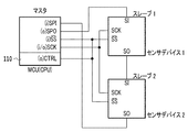
- FIG. 27 is a system configuration diagram for explaining the operation in the block diagram shown in FIG. 29, and is a system configuration diagram when an SPI bus is used for a single interface.
- the CPU, slave 1 and slave 2 have an SPI interface and communicate with each other via the SPI bus.
- Slave 1 and slave 2 are set from the CPU.
- each sensor device is cascade-connected to the MCU (CPU) 110, and the slave selection signal line (SS) and the serial clock signal line (SCK) are shared between the sensor devices.
- the setting register and data register of each sensor device appear to the MCU 110 as one long shift register.
- the MCU 110 becomes the SPI master.
- the serial clock signal terminal (SCK) of the MCU 110 is an output terminal.
- the slave selection signal terminal (SS) and the serial clock signal terminal (SCK) of the sensor device are all input terminals.
- the MCU 110 activates a slave selection signal line (SS) shared between the sensor devices through the CTRL terminal. This slave selection signal is also input to the slave selection signal input terminal (SS) of the MCU 110 itself.
- SS slave selection signal line
- the MCU 110 uses the serial clock signal terminal and the serial output signal terminal to access the register chain in which the setting registers of all the sensor devices are cascade-connected to set the measurement number ratio. Furthermore, a setting for instructing one of the sensor devices to generate a count command, a desired timing at which measurement data is to be transmitted (specified by how many times it is transmitted), and a desired number of measurement data to be transmitted Set.
- the MCU 110 cancels the master state and sets itself to the slave mode.
- the serial clock signal terminal (SCK) of the MCU 110 is an input terminal.
- the sensor device set to generate the count command changes its slave selection signal terminal (SS) and serial clock signal terminal (SCK) to output terminals.
- the sensor device set to generate the count command becomes the SPI master at the timing managed by itself and outputs the count command to the slave selection signal line (SS).
- the count command is, for example, a falling edge of the slave selection signal line (SS). This count command is received simultaneously by each sensor device.
- Each sensor device counts a count command and performs measurement autonomously at a set measurement number ratio.
- the sensor device set to generate the count command detects the timing at which the set measurement data is to be transmitted, the number of measurement data to be transmitted while the slave selection signal line (SS) remains active Is sent to the serial clock signal line (SCK).
- the measurement data is sequentially transferred from the register chain in which the data registers of all the sensor devices are cascade-connected to the MCU, and the MCU can collect the desired measurement data.
- FIG. 30 is a block diagram for explaining a sensor data processing system using a plurality of sensor devices according to the eighth embodiment of the present invention.
- the sensor devices 101, 102, and 103 having the functions of the present invention, the MCU 110 to which the sensor devices 101, 102, and 103 are connected, and an external periodic signal generation unit 112 that generates a count command. Composed.
- the periodic signal generator 112 sends a count command to each sensor device 101, 102, 103.
- the MCU 110 has a function of setting the measurement number ratio and the like and transmitting the information to the sensor devices 101, 102, and 103 and a function of receiving data from the sensor devices 101, 102, and 103.
- FIG. 31 is a block diagram for explaining a sensor data processing system using a plurality of sensor devices according to the ninth embodiment of the present invention, and shows another embodiment of the eighth embodiment shown in FIG. Yes.
- each sensor device 101, 102, 103 having the function of the present invention, an MCU 110 to which each sensor device 101, 102, 103 is connected, and an external periodic signal generation unit 112 that generates a count command are included.
- the MCU 110 sets the measurement number ratio and transmits the information to the sensor devices 101, 102, and 103.
- a line for receiving the count command is prepared, the count command is transmitted from the external periodic signal generation unit 112 to each of the sensor devices 101, 102, and 103, and the sensor devices 101, 102, and 103 and the MCU 110 receive the count command.
- each of the sensor devices 101, 102, and 103 performs measurement autonomously at the set measurement number ratio.
- the MCU 110 counts the received count command and, when the set number of times is reached, retrieves data from the corresponding sensor devices 101, 102, 103.
- a sensor device with a sampling function that can arbitrarily set and maintain the measurement number ratio among a plurality of sensor devices and can autonomously measure while maintaining the set measurement number ratio between sensor devices was used.
- a sensor data processing system can be provided.
Landscapes
- Engineering & Computer Science (AREA)
- Radar, Positioning & Navigation (AREA)
- Remote Sensing (AREA)
- Physics & Mathematics (AREA)
- General Physics & Mathematics (AREA)
- Automation & Control Theory (AREA)
- Aviation & Aerospace Engineering (AREA)
- Arrangements For Transmission Of Measured Signals (AREA)
- Testing Or Calibration Of Command Recording Devices (AREA)
Priority Applications (4)
| Application Number | Priority Date | Filing Date | Title |
|---|---|---|---|
| CN201280038104.0A CN103733030B (zh) | 2012-02-24 | 2012-02-24 | 带采样功能的传感器设备以及使用了该传感器设备的传感器数据处理系统 |
| PCT/JP2012/001275 WO2013124903A1 (fr) | 2012-02-24 | 2012-02-24 | Dispositif de type capteur à fonction d'échantillonnage et système de traitement de données de capteur l'utilisant |
| EP12869414.8A EP2818836B1 (fr) | 2012-02-24 | 2012-02-24 | Dispositif de type capteur à fonction d'échantillonnage et système de traitement de données de capteur l'utilisant |
| US14/344,617 US9534923B2 (en) | 2012-02-24 | 2012-02-24 | Sensor device with sampling function, and sensor data processing system using same |
Applications Claiming Priority (1)
| Application Number | Priority Date | Filing Date | Title |
|---|---|---|---|
| PCT/JP2012/001275 WO2013124903A1 (fr) | 2012-02-24 | 2012-02-24 | Dispositif de type capteur à fonction d'échantillonnage et système de traitement de données de capteur l'utilisant |
Publications (1)
| Publication Number | Publication Date |
|---|---|
| WO2013124903A1 true WO2013124903A1 (fr) | 2013-08-29 |
Family
ID=49005129
Family Applications (1)
| Application Number | Title | Priority Date | Filing Date |
|---|---|---|---|
| PCT/JP2012/001275 Ceased WO2013124903A1 (fr) | 2012-02-24 | 2012-02-24 | Dispositif de type capteur à fonction d'échantillonnage et système de traitement de données de capteur l'utilisant |
Country Status (4)
| Country | Link |
|---|---|
| US (1) | US9534923B2 (fr) |
| EP (1) | EP2818836B1 (fr) |
| CN (1) | CN103733030B (fr) |
| WO (1) | WO2013124903A1 (fr) |
Cited By (2)
| Publication number | Priority date | Publication date | Assignee | Title |
|---|---|---|---|---|
| CN105320072A (zh) * | 2014-06-13 | 2016-02-10 | 发那科株式会社 | 数值控制系统 |
| US20210242954A1 (en) * | 2015-12-04 | 2021-08-05 | Infineon Technologies Ag | Robust high speed sensor interface for remote sensors |
Families Citing this family (4)
| Publication number | Priority date | Publication date | Assignee | Title |
|---|---|---|---|---|
| JP6311871B2 (ja) * | 2014-04-17 | 2018-04-18 | セイコーエプソン株式会社 | 物理量検出用回路、物理量検出装置、物理量計測システム、電子機器、移動体及び物理量計測データ生成方法 |
| WO2018051538A1 (fr) | 2016-09-15 | 2018-03-22 | アルプス電気株式会社 | Dispositif de mesure de quantité physique |
| US11194386B1 (en) | 2019-05-22 | 2021-12-07 | Facebook Technologies, Llc | Artificial reality wearable magnetic sensor system for body pose tracking |
| JP7700597B2 (ja) * | 2021-09-14 | 2025-07-01 | オムロン株式会社 | 情報収集システムおよび情報収集方法 |
Citations (8)
| Publication number | Priority date | Publication date | Assignee | Title |
|---|---|---|---|---|
| JPH0989598A (ja) * | 1995-09-27 | 1997-04-04 | Yokogawa Electric Corp | 記録装置 |
| JP2001188011A (ja) * | 1999-10-20 | 2001-07-10 | Murata Mfg Co Ltd | 振動ジャイロ |
| JP2001280974A (ja) | 2000-03-28 | 2001-10-10 | Clarion Co Ltd | Drセンササンプリング機能付きgpsレシーバ |
| JP2003014462A (ja) * | 2001-07-02 | 2003-01-15 | Nec Corp | 人工衛星の姿勢検出装置 |
| JP2003057077A (ja) * | 2001-08-20 | 2003-02-26 | Mitsubishi Electric Corp | データ収集装置 |
| JP2009204603A (ja) | 2008-01-31 | 2009-09-10 | Victor Co Of Japan Ltd | 変換係数の導出方法およびナビゲーション装置 |
| JP2010127857A (ja) | 2008-11-28 | 2010-06-10 | Asahi Kasei Electronics Co Ltd | 磁気センサ |
| JP2012047585A (ja) * | 2010-08-26 | 2012-03-08 | Asahi Kasei Electronics Co Ltd | サンプリング機能付きセンサデバイス及びそれを用いたセンサデータ処理システム |
Family Cites Families (8)
| Publication number | Priority date | Publication date | Assignee | Title |
|---|---|---|---|---|
| US5016186A (en) * | 1988-02-09 | 1991-05-14 | Mitsubishi Jukogyo Kabushiki Kaisha | Method of detecting noise disappearance and detecting device therefor |
| EP0766186A3 (fr) | 1995-09-27 | 1997-12-29 | Yokogawa Electric Corporation | Processeur de données |
| EP1094297B1 (fr) | 1999-10-20 | 2005-07-27 | Murata Manufacturing Co., Ltd. | Méthode pour mesurer la vitesse angulaire et gyroscope à vibration |
| DE10119396A1 (de) * | 2001-04-20 | 2002-10-24 | Abb Research Ltd | Verfahren zur Bestimmung der zeitlichen Reihenfolge des Auftretens von Ereignissen in einem System mit einer Vielzahl von Sensoren und/oder Aktoren |
| WO2007009458A2 (fr) * | 2005-07-15 | 2007-01-25 | Pinocchio Data Systems Aps | Algorithme de synchronisation de temps destine a la mesure de systemes avec des retards aleatoires |
| JP4417951B2 (ja) * | 2006-12-28 | 2010-02-17 | 株式会社東芝 | 機器監視方法および機器監視システム |
| US8140263B2 (en) | 2008-01-31 | 2012-03-20 | Victor Company Of Japan, Limited | Method for deriving conversion coefficient used for specifying position from value detected by various sensors, and navigation apparatus |
| US8433533B2 (en) * | 2008-12-30 | 2013-04-30 | Baker Hughes Incorporated | High resolution sensor with scalable sample rate |
-
2012
- 2012-02-24 US US14/344,617 patent/US9534923B2/en not_active Expired - Fee Related
- 2012-02-24 CN CN201280038104.0A patent/CN103733030B/zh not_active Expired - Fee Related
- 2012-02-24 WO PCT/JP2012/001275 patent/WO2013124903A1/fr not_active Ceased
- 2012-02-24 EP EP12869414.8A patent/EP2818836B1/fr not_active Not-in-force
Patent Citations (8)
| Publication number | Priority date | Publication date | Assignee | Title |
|---|---|---|---|---|
| JPH0989598A (ja) * | 1995-09-27 | 1997-04-04 | Yokogawa Electric Corp | 記録装置 |
| JP2001188011A (ja) * | 1999-10-20 | 2001-07-10 | Murata Mfg Co Ltd | 振動ジャイロ |
| JP2001280974A (ja) | 2000-03-28 | 2001-10-10 | Clarion Co Ltd | Drセンササンプリング機能付きgpsレシーバ |
| JP2003014462A (ja) * | 2001-07-02 | 2003-01-15 | Nec Corp | 人工衛星の姿勢検出装置 |
| JP2003057077A (ja) * | 2001-08-20 | 2003-02-26 | Mitsubishi Electric Corp | データ収集装置 |
| JP2009204603A (ja) | 2008-01-31 | 2009-09-10 | Victor Co Of Japan Ltd | 変換係数の導出方法およびナビゲーション装置 |
| JP2010127857A (ja) | 2008-11-28 | 2010-06-10 | Asahi Kasei Electronics Co Ltd | 磁気センサ |
| JP2012047585A (ja) * | 2010-08-26 | 2012-03-08 | Asahi Kasei Electronics Co Ltd | サンプリング機能付きセンサデバイス及びそれを用いたセンサデータ処理システム |
Non-Patent Citations (1)
| Title |
|---|
| See also references of EP2818836A4 |
Cited By (4)
| Publication number | Priority date | Publication date | Assignee | Title |
|---|---|---|---|---|
| CN105320072A (zh) * | 2014-06-13 | 2016-02-10 | 发那科株式会社 | 数值控制系统 |
| US9791850B2 (en) | 2014-06-13 | 2017-10-17 | Fanuc Corporation | Numerical control system |
| US20210242954A1 (en) * | 2015-12-04 | 2021-08-05 | Infineon Technologies Ag | Robust high speed sensor interface for remote sensors |
| US11728916B2 (en) * | 2015-12-04 | 2023-08-15 | Infineon Technologies Ag | Robust high speed sensor interface for remote sensors |
Also Published As
| Publication number | Publication date |
|---|---|
| CN103733030A (zh) | 2014-04-16 |
| EP2818836B1 (fr) | 2016-04-27 |
| CN103733030B (zh) | 2016-01-20 |
| EP2818836A1 (fr) | 2014-12-31 |
| EP2818836A4 (fr) | 2015-03-04 |
| US20140350894A1 (en) | 2014-11-27 |
| US9534923B2 (en) | 2017-01-03 |
Similar Documents
| Publication | Publication Date | Title |
|---|---|---|
| CN107092568B (zh) | 在低功耗系统中处理数据的数据通信接口 | |
| US10159053B2 (en) | Low-latency low-uncertainty timer synchronization mechanism across multiple devices | |
| JP5501900B2 (ja) | サンプリング機能付きセンサデバイス及びそれを用いたセンサデータ処理システム | |
| US9534923B2 (en) | Sensor device with sampling function, and sensor data processing system using same | |
| US8731002B2 (en) | Synchronization, re-synchronization, addressing, and serialized signal processing for daisy-chained communication devices | |
| CN102183253B (zh) | 一种位置和姿态测量系统的软件时间同步方法 | |
| US9986035B2 (en) | Synchronous measurement system | |
| JP6210187B2 (ja) | 集積回路装置、物理量測定装置、電子機器および移動体 | |
| US20160036544A1 (en) | Synchronous measurement system | |
| JP5581356B2 (ja) | 多点計測システムおよび時刻同期方法 | |
| JP4901813B2 (ja) | マルチコントローラシステム | |
| JP6240791B2 (ja) | 双方向同期/制御ワード線を有するシリアル時分割多重バス | |
| WO2012134930A1 (fr) | Système, appareil et procédé pour des communications multiplexées par répartition dans le temps | |
| KR20200110219A (ko) | 직렬 주변기기 인터페이스 마스터 | |
| WO2011128605A3 (fr) | Mesure gyroscopique dans un systeme de navigation | |
| CN103034236B (zh) | 一种基于时分复用的多星敏感器时序同步处理方法 | |
| US9584910B2 (en) | Sound gathering system | |
| CN118828419A (zh) | 主通信集成电路、通信系统及使用主通信集成电路的通信方法 | |
| CN116528194A (zh) | 用于自动驾驶系统的同步系统、同步方法 | |
| CN104361299B (zh) | 安全系统、多重安全控制系统及读取位置信息的方法 | |
| CN103345457A (zh) | 通过1553b总线确保卫星辅助数据高精度发送的方法 | |
| CN208579770U (zh) | 一种室内定位系统 | |
| WO2019144645A1 (fr) | Dispositif de chronométrage | |
| TWI267650B (en) | Global positioning apparatus and method for saving power thereof | |
| CN209861170U (zh) | 物联网定位终端 |
Legal Events
| Date | Code | Title | Description |
|---|---|---|---|
| 121 | Ep: the epo has been informed by wipo that ep was designated in this application |
Ref document number: 12869414 Country of ref document: EP Kind code of ref document: A1 |
|
| WWE | Wipo information: entry into national phase |
Ref document number: 2012869414 Country of ref document: EP |
|
| WWE | Wipo information: entry into national phase |
Ref document number: 14344617 Country of ref document: US |
|
| NENP | Non-entry into the national phase |
Ref country code: DE |
|
| NENP | Non-entry into the national phase |
Ref country code: JP |