WO2013125044A1 - 風車制御装置及びその方法並びに風力発電システム - Google Patents
風車制御装置及びその方法並びに風力発電システム Download PDFInfo
- Publication number
- WO2013125044A1 WO2013125044A1 PCT/JP2012/054654 JP2012054654W WO2013125044A1 WO 2013125044 A1 WO2013125044 A1 WO 2013125044A1 JP 2012054654 W JP2012054654 W JP 2012054654W WO 2013125044 A1 WO2013125044 A1 WO 2013125044A1
- Authority
- WO
- WIPO (PCT)
- Prior art keywords
- command
- output
- windmill
- command information
- setting
- Prior art date
- Legal status (The legal status is an assumption and is not a legal conclusion. Google has not performed a legal analysis and makes no representation as to the accuracy of the status listed.)
- Ceased
Links
Images


Classifications
-
- F—MECHANICAL ENGINEERING; LIGHTING; HEATING; WEAPONS; BLASTING
- F03—MACHINES OR ENGINES FOR LIQUIDS; WIND, SPRING, OR WEIGHT MOTORS; PRODUCING MECHANICAL POWER OR A REACTIVE PROPULSIVE THRUST, NOT OTHERWISE PROVIDED FOR
- F03D—WIND MOTORS
- F03D7/00—Controlling wind motors
- F03D7/02—Controlling wind motors the wind motors having rotation axis substantially parallel to the air flow entering the rotor
- F03D7/028—Controlling wind motors the wind motors having rotation axis substantially parallel to the air flow entering the rotor controlling wind motor output power
- F03D7/0284—Controlling wind motors the wind motors having rotation axis substantially parallel to the air flow entering the rotor controlling wind motor output power in relation to the state of the electric grid
-
- F—MECHANICAL ENGINEERING; LIGHTING; HEATING; WEAPONS; BLASTING
- F03—MACHINES OR ENGINES FOR LIQUIDS; WIND, SPRING, OR WEIGHT MOTORS; PRODUCING MECHANICAL POWER OR A REACTIVE PROPULSIVE THRUST, NOT OTHERWISE PROVIDED FOR
- F03D—WIND MOTORS
- F03D7/00—Controlling wind motors
-
- F—MECHANICAL ENGINEERING; LIGHTING; HEATING; WEAPONS; BLASTING
- F03—MACHINES OR ENGINES FOR LIQUIDS; WIND, SPRING, OR WEIGHT MOTORS; PRODUCING MECHANICAL POWER OR A REACTIVE PROPULSIVE THRUST, NOT OTHERWISE PROVIDED FOR
- F03D—WIND MOTORS
- F03D7/00—Controlling wind motors
- F03D7/02—Controlling wind motors the wind motors having rotation axis substantially parallel to the air flow entering the rotor
- F03D7/04—Automatic control; Regulation
- F03D7/042—Automatic control; Regulation by means of an electrical or electronic controller
- F03D7/047—Automatic control; Regulation by means of an electrical or electronic controller characterised by the controller architecture, e.g. multiple processors or data communications
-
- F—MECHANICAL ENGINEERING; LIGHTING; HEATING; WEAPONS; BLASTING
- F03—MACHINES OR ENGINES FOR LIQUIDS; WIND, SPRING, OR WEIGHT MOTORS; PRODUCING MECHANICAL POWER OR A REACTIVE PROPULSIVE THRUST, NOT OTHERWISE PROVIDED FOR
- F03D—WIND MOTORS
- F03D7/00—Controlling wind motors
- F03D7/02—Controlling wind motors the wind motors having rotation axis substantially parallel to the air flow entering the rotor
- F03D7/04—Automatic control; Regulation
- F03D7/042—Automatic control; Regulation by means of an electrical or electronic controller
- F03D7/048—Automatic control; Regulation by means of an electrical or electronic controller controlling wind farms
-
- F—MECHANICAL ENGINEERING; LIGHTING; HEATING; WEAPONS; BLASTING
- F03—MACHINES OR ENGINES FOR LIQUIDS; WIND, SPRING, OR WEIGHT MOTORS; PRODUCING MECHANICAL POWER OR A REACTIVE PROPULSIVE THRUST, NOT OTHERWISE PROVIDED FOR
- F03D—WIND MOTORS
- F03D9/00—Adaptations of wind motors for special use; Combinations of wind motors with apparatus driven thereby; Wind motors specially adapted for installation in particular locations
- F03D9/20—Wind motors characterised by the driven apparatus
- F03D9/25—Wind motors characterised by the driven apparatus the apparatus being an electrical generator
- F03D9/255—Wind motors characterised by the driven apparatus the apparatus being an electrical generator connected to electrical distribution networks; Arrangements therefor
-
- F—MECHANICAL ENGINEERING; LIGHTING; HEATING; WEAPONS; BLASTING
- F05—INDEXING SCHEMES RELATING TO ENGINES OR PUMPS IN VARIOUS SUBCLASSES OF CLASSES F01-F04
- F05B—INDEXING SCHEME RELATING TO WIND, SPRING, WEIGHT, INERTIA OR LIKE MOTORS, TO MACHINES OR ENGINES FOR LIQUIDS COVERED BY SUBCLASSES F03B, F03D AND F03G
- F05B2270/00—Control
- F05B2270/30—Control parameters, e.g. input parameters
- F05B2270/337—Electrical grid status parameters, e.g. voltage, frequency or power demand
-
- Y—GENERAL TAGGING OF NEW TECHNOLOGICAL DEVELOPMENTS; GENERAL TAGGING OF CROSS-SECTIONAL TECHNOLOGIES SPANNING OVER SEVERAL SECTIONS OF THE IPC; TECHNICAL SUBJECTS COVERED BY FORMER USPC CROSS-REFERENCE ART COLLECTIONS [XRACs] AND DIGESTS
- Y02—TECHNOLOGIES OR APPLICATIONS FOR MITIGATION OR ADAPTATION AGAINST CLIMATE CHANGE
- Y02E—REDUCTION OF GREENHOUSE GAS [GHG] EMISSIONS, RELATED TO ENERGY GENERATION, TRANSMISSION OR DISTRIBUTION
- Y02E10/00—Energy generation through renewable energy sources
- Y02E10/70—Wind energy
- Y02E10/72—Wind turbines with rotation axis in wind direction
-
- Y—GENERAL TAGGING OF NEW TECHNOLOGICAL DEVELOPMENTS; GENERAL TAGGING OF CROSS-SECTIONAL TECHNOLOGIES SPANNING OVER SEVERAL SECTIONS OF THE IPC; TECHNICAL SUBJECTS COVERED BY FORMER USPC CROSS-REFERENCE ART COLLECTIONS [XRACs] AND DIGESTS
- Y02—TECHNOLOGIES OR APPLICATIONS FOR MITIGATION OR ADAPTATION AGAINST CLIMATE CHANGE
- Y02E—REDUCTION OF GREENHOUSE GAS [GHG] EMISSIONS, RELATED TO ENERGY GENERATION, TRANSMISSION OR DISTRIBUTION
- Y02E10/00—Energy generation through renewable energy sources
- Y02E10/70—Wind energy
- Y02E10/76—Power conversion electric or electronic aspects
Definitions
- the present invention relates to a windmill control device and method, and a wind power generation system.
- Japanese Patent No. 4782245 discloses system disturbance based on conversion information indicating a preset relationship between a frequency fluctuation amount and an active power command value.
- a method for controlling the effective power of a wind turbine in a suppressing direction is disclosed.
- a first aspect of the present invention is a windmill control device that is applied to a wind power generation system in which outputs of a plurality of windmills are supplied to a power system through a common interconnection point, and is provided for each of the windmills.
- the first setting means for setting the first command information for generating the output command for suppressing the frequency fluctuation at the interconnection point, and the output command for generating the output command for suppressing the frequency fluctuation of the output of the corresponding windmill
- a second processing means for setting second command information; and when a system disturbance occurs in which the frequency fluctuation at the interconnection point exceeds a predetermined first threshold, the second command information is selected at an initial stage of the system disturbance
- a wind turbine control device comprising: selection means for selecting the first command information at a later stage of the system disturbance; and command generation means for generating an output command using the command information selected by the selection means.
- a wind turbine control method applied to a wind power generation system in which outputs of a plurality of wind turbines are supplied to an electric power system through a common interconnection point, the frequency fluctuation at the interconnection point.
- a first setting process for setting first command information for generating an output command for suppressing the output and a second command information for generating an output command for suppressing the frequency fluctuation of the output of the corresponding wind turbine 2 When the system disturbance in which the frequency fluctuation at the interconnection point exceeds a predetermined first threshold occurs, the second command information is selected at the initial stage of the system disturbance, and the latter stage of the system disturbance. And a command generation process for generating an output command using the command information selected in the selection process.
- a third aspect of the present invention is a wind power generation system including a plurality of windmills, and an output of each of the windmills is supplied to an electric power system through a common interconnection point, and controls the output at the interconnection point And a plurality of wind turbine control units that are provided corresponding to the wind turbines and control the output of the corresponding wind turbines, and the central control unit outputs an output command that suppresses frequency fluctuations at the interconnection points.
- First processing means for setting first command information for generating the first command information, and transmitting means for transmitting the first command information of each windmill set by the first processing means to each windmill,
- the windmill control means suppresses frequency fluctuations in the output of the corresponding windmill, receiving means for receiving the first command information from the central control means, first setting means for setting the received first command information, and
- a second processing means for setting second command information for generating an output command, and an initial stage of the system disturbance when a system disturbance in which a frequency fluctuation at the interconnection point exceeds a predetermined first threshold value occurs.
- Selecting means for selecting the second command information, and selecting the first command information at a later stage of the system disturbance; and command generating means for generating an output command using the command information selected by the selection means; Is a wind power generation system.
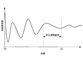
- FIG. 1 It is a figure showing the whole wind power system composition concerning one embodiment of the present invention. It is an external view of the windmill shown in FIG. It is the schematic diagram which showed schematically the electric structure of the windmill shown in FIG. It is the figure which showed an example of the hardware constitutions of the central control apparatus shown in FIG. It is the functional block diagram which mainly showed the function regarding frequency suppression control among the functions with which the central control apparatus and the windmill control apparatus which were shown in FIG. It is the figure which showed an example of the conversion information. It is a figure for demonstrating the initial stage and late stage of system disturbance.
- FIG. 1 is a diagram illustrating an overall configuration of a wind power generation system according to the present embodiment.
- the wind power generation system 1 includes a plurality of wind turbines 10-1,..., 10-n (hereinafter, when all the wind turbines are indicated, a reference numeral “10” is attached to each wind turbine). In this case, reference numerals “10-1”, “10-n”, etc. are attached.)
- a central controller 2 that gives a first correction value to each wind turbine 10.
- all the windmills 10 are variable speed windmills capable of controlling the rotation speed according to the wind speed.
- the electric power output from each windmill 10 is supplied to the electric power grid
- the system frequency of the interconnection point A is measured by the frequency detection unit 25 (see FIG. 5) and is output to the central controller 2.
- the central control device 2 is a control device that controls the output at the interconnection point A.
- a request notified from a power management room (for example, a power company) that manages the power of the power system 3 An active power command is set for each wind turbine to match the output at the interconnection point A with the frequency and the required power value.
- the active power command for each wind turbine set by the central controller 2 is transmitted to the wind turbine control device 20 included in each wind turbine 10-1,..., 10-n, and output control based on this active power command is performed for each wind turbine. Done in
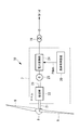
- FIG. 2 is an external view of the windmill 10, and FIG. 3 is a schematic diagram illustrating an electrical configuration of the windmill 10.
- the wind turbine 10 is provided in the nacelle 7 so as to be rotatable around a substantially horizontal axis line, a tower 6 standing on the foundation 5, a nacelle 7 installed on the upper end of the tower 6, and the like. And a rotor head 8.
- a plurality of blades 9 are radially attached to the rotor head 8 around its rotational axis.
- the blade 9 is connected so as to be rotatable with respect to the rotor head 8 according to operating conditions, and the pitch angle can be changed.
- a speed increaser 22 and a generator 23 are mechanically connected to the rotating shaft 21 of the rotor head 8.
- the generator 23 may be a synchronous generator or an induction generator. It is also possible to adopt a configuration in which the speed increaser 23 is not provided.
- the rotor head 8 is rotated around the rotation axis by the force of the wind hitting the blade 9 from the rotation axis direction of the rotor head 8, and the rotation force is increased by the speed increaser 22 and transmitted to the generator 23. Converted to electric power.
- the electric power generated by the generator 23 is converted into electric power corresponding to the electric power system 3 by the electric power converter 24 and supplied to the electric power system 1 through the transformer 19.
- the power conversion unit 24 is controlled by the windmill control device 20.
- the windmill control device 20 has a function of controlling the output of the generator 23 by controlling the power converter 24, a function of controlling the pitch angle of the blade 9, and the like.
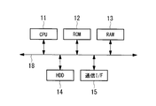
- the central control device 2 and the windmill control device 20 include a computer.
- a CPU 11 and a ROM (Read Only Memory) 12 for storing a program executed by the CPU 11,
- a RAM (Random Access Memory) 13 functioning as a work area when executing each program
- a hard disk drive (HDD) 14 as a mass storage device
- a communication interface 15 for connecting to a communication network are provided.
- These units are connected via a bus 18.
- the central control device 2 may include an access unit to which an external storage device is attached, an input unit including a keyboard and a mouse, a display unit including a liquid crystal display device that displays data, and the like.
- the storage medium for storing the program executed by the CPU 11 is not limited to the ROM 12.
- other auxiliary storage devices such as a magnetic disk, a magneto-optical disk, and a semiconductor memory may be used.
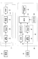
- FIG. 5 is a functional block diagram mainly showing functions related to frequency control that operates when, for example, system disturbance (frequency fluctuation) occurs, among the functions of the central control device 2 and the windmill control device 20.
- Central controller 2 generates first command information for suppressing frequency fluctuations at interconnection point A for each windmill, and generates the generated first command information for each windmill 10-1,. It transmits to the control apparatus 20.
- the central controller 2 includes a first processing unit 31 and a transmission unit 32 as shown in FIG.
- the first processing unit 31 includes a deviation calculating unit 33, a parameter converting unit 34, and a correction value setting unit 35.
- the deviation calculation unit 33 calculates a system frequency deviation ⁇ f grid that is a deviation between the system frequency detected by the frequency detection unit 25 and the rated frequency notified from the power management room. That is, the system frequency deviation ⁇ f grid is expressed by the following equation (1).
- f ref is a rated frequency and f grid is a system frequency.
- the parameter conversion unit 34 has conversion information in which the relationship between the frequency deviation ⁇ f and the power correction value ⁇ P is set, and corresponds to the system frequency deviation ⁇ f grid calculated by the deviation calculation unit 33 using this conversion information.
- the grid power correction value ⁇ P grid to be acquired is acquired.
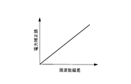
- Fig. 6 shows an example of conversion information.
- the horizontal axis indicates the frequency deviation ⁇ f
- the vertical axis indicates the power correction value ⁇ P.
- the conversion characteristics shown in FIG. 6 can be arbitrarily set according to the design of the wind turbine, and here, the slope is defined as a positive linear function.
- the grid power correction value ⁇ P grid acquired by the parameter conversion unit 34 is output to the correction value setting unit 35.
- the correction value setting unit 35 divides the grid power correction value ⁇ P grid by the number n of wind turbines in operation to equally distribute the grid power correction value ⁇ P grid to each wind turbine, and the first power corresponding to each wind turbine.
- Correction values ⁇ P id — n ,..., ⁇ P id — n are set.
- a weighting coefficient is set in advance for each wind turbine 10-1,..., 10-n, and the distribution of the grid power correction value ⁇ P grid to each wind turbine during operation is determined using this weighting coefficient. It is good to do.
- the first power correction values ⁇ P id — 1,..., ⁇ P id — n of the wind turbines set in this way are transmitted to the wind turbine controller 20 of each wind turbine as the first command information.
- Each windmill control device 20 includes a reception unit 40, a first setting unit 41, a second processing unit 42, a selection unit 43, a state determination unit 44, and an active power command generation unit 45. Since the configuration of the windmill control device 20 included in each of the windmills 10-1,..., 10-n is the same, the configuration of the windmill control device 20 of the windmill 10-1 is a representative example below for convenience of explanation. Will be described.
- the receiving unit 40 receives the first power correction value ⁇ P id — 1 transmitted from the central control device 2 and outputs it to the first setting unit 41.
- the first setting unit 41 sets the first power correction value ⁇ P id — 1 received by the receiving unit 40.
- the first power correction value ⁇ P id — 1 set by the first setting unit 41 is a power correction value for suppressing fluctuations in the system frequency.
- the second processing unit 42 sets second command information for generating an output command for suppressing the frequency fluctuation of the output of the corresponding wind turbine 10-1.
- the second processing unit 42 includes a deviation calculating unit 46 and a parameter converting unit 47.
- the deviation calculation unit 46 receives the output frequency of the windmill 10-1 detected by the frequency detection unit 26 (hereinafter referred to as “windmill frequency”).
- the deviation calculating unit 46 calculates a wind turbine frequency deviation ⁇ f wd_1 between the input wind turbine frequency and the rated frequency. That is, the wind turbine frequency deviation ⁇ f wd — 1 is expressed by the following equation (2).
- f ref is the rated frequency
- f wd_1 is the wind turbine frequency of the wind turbine 10-1.
- the parameter conversion unit 47 has, for example, the conversion information shown in FIG. 6 and uses the conversion information to obtain the wind turbine power correction value ⁇ P wd_1 corresponding to the wind turbine frequency deviation ⁇ f wd_1 calculated by the deviation calculation unit 46. It is acquired and set as a second power correction value (second command information).
- the selection unit 43 receives the first power correction value set by the first setting unit 41 and the second power correction value set by the second processing unit 42. When the system disturbance occurs, the selection unit 43 selects the second power correction value at the initial stage of the system disturbance, selects the first power correction value at the later stage of the system disturbance, and generates an active power command. To the unit 45. The occurrence of the system disturbance, the initial stage of the system disturbance, and the later stage of the system disturbance are determined by an input signal from the state determination unit 44.
- the state determination unit 44 detects the occurrence of system disturbance when the frequency fluctuation at the interconnection point A exceeds a predetermined first threshold value, and outputs a High signal to the selection unit 43. In addition, after the occurrence of the disturbance, when the state in which the fluctuation range of the system frequency is less than the second threshold set to a value equal to or less than the first threshold is maintained for a predetermined period or longer, the transition from the initial stage to the later stage is performed. Determination is made and the output signal is switched from the high signal to the low signal.
- the selection unit 43 selects the second power correction value ⁇ P wd_1 during the period in which the High signal is input from the state determination unit 44. In addition, the selection unit 43 selects the first power correction value ⁇ P id_1 during the period when the Low signal is input from the state determination unit 44, and outputs the first power correction value ⁇ P id_1 to the active power command generation unit 45.
- the active power command generation unit 45 has a reference active power command as a reference, and adds the first power correction value or the second power correction value input from the selection unit 43 to the reference active power command.
- an active power command is generated.
- a control signal Pdem for controlling the power conversion unit 24 is generated based on the active power command, and is output to the power conversion unit 24.
- the reference active power command may be a fixed value, or a predetermined calculation is performed using the current output of the generator 23, the rotational speed of the rotor head 8, the pitch angle of the blade 9, and the wind speed. May be a value that is sequentially calculated by.
- the central control device 2 sets the first power correction value such that the system frequency becomes the rated frequency at a predetermined time interval, and the first power correction value is the wind turbine of each wind turbine. It is transmitted to the control device 20.
- the reception unit 40 receives the first power correction value from the central control device 2, and the first setting unit 41 sets the first power correction value. Further, the second processing unit 42 sets a second power correction value with the output frequency of the corresponding windmill as the rated frequency.
- the state determination unit 44 outputs a High signal when it is detected that a system disturbance has occurred at time T ⁇ b> 0, and then, when time passes, at time T ⁇ b> 1 in FIG. 7.
- the state where the frequency fluctuation at the interconnection point A is less than the second threshold is maintained for a predetermined period, it is detected that the state has shifted to the later stage of the system disturbance, and the output signal is changed from the High signal to Low. Switch to signal.
- the second power correction value is selected in the initial stage from the occurrence of the system disturbance (period T0 to T1 in FIG. 7), and after the transition from the initial stage of the system disturbance to the later stage In (after time T1 in FIG. 7), the first power correction value is selected. Therefore, in the initial stage of system disturbance occurrence, an active power command using the second power correction value that suppresses fluctuations in the wind turbine frequency is generated by the active power command generator 45, and the output of the wind turbine is generated based on this active power command. Is controlled. Further, in the later stage of the system disturbance, the active power command using the first power correction value that suppresses the fluctuation of the system frequency is generated by the active power command generation unit 45, and the output of the windmill is generated based on the active power command. Be controlled.
- the wind turbine control device 20 and the method thereof and the wind power generation system 1 according to the present embodiment when a system disturbance occurs, the frequency fluctuations of individual outputs of the wind turbine in the initial stage of the system disturbance. Output control is performed in each wind turbine, and in the later stage of the system disturbance, output control is performed in each wind turbine to suppress the system frequency at the connection point A.
- the control that suppresses the output frequency for each wind turbine is more responsive than the control that suppresses the system frequency. Therefore, it is possible to effectively suppress the frequency fluctuation at the interconnection point A by selecting the control that suppresses the output frequency fluctuation for each wind turbine in the initial stage of the system disturbance.
- the state determination unit 44 may have these two conditions, and may determine that the system has shifted to the later stage of the system disturbance when one of the two conditions is satisfied.
- the occurrence of the system disturbance and the transition from the initial stage to the late stage are determined based on the system frequency, but instead, the output frequency of each windmill is used to generate the system disturbance and the initial stage.
- the transition from the stage to the later stage may be determined.
- the first command information and the second command information respectively set by the first setting unit and the second processing unit are the power correction values. Instead, the first power correction value is reflected.
- the second active power command in which the first active power command and the second power correction value are reflected may be set as the first command information and the second command information.
- an active power command generation unit 45 may be provided between the first setting unit 41 and the selection unit 43 and between the parameter conversion unit 47 and the selection unit 43. Further, in this case, the central control device 2 generates a first active power command that suppresses frequency fluctuations at the interconnection point A for each wind turbine, and the generated first active power command is sent to each wind turbine 10. It is good also as transmitting. In this case, the first active power command received from the central control device 2 is set by the first setting unit 41.
Landscapes
- Engineering & Computer Science (AREA)
- Life Sciences & Earth Sciences (AREA)
- Sustainable Development (AREA)
- Sustainable Energy (AREA)
- Chemical & Material Sciences (AREA)
- Combustion & Propulsion (AREA)
- Mechanical Engineering (AREA)
- General Engineering & Computer Science (AREA)
- Power Engineering (AREA)
- Control Of Eletrric Generators (AREA)
- Wind Motors (AREA)
Priority Applications (6)
| Application Number | Priority Date | Filing Date | Title |
|---|---|---|---|
| EP12801792.8A EP2818699B1 (de) | 2012-02-24 | 2012-02-24 | Windturbinensteuerungsvorrichtung und -verfahren sowie windenergieerzeugungssystem |
| KR1020127033763A KR20130106287A (ko) | 2012-02-24 | 2012-02-24 | 풍차 제어 장치 및 그 방법 및 풍력 발전 시스템 |
| JP2012556731A JP5325348B1 (ja) | 2012-02-24 | 2012-02-24 | 風車制御装置及びその方法並びに風力発電システム |
| PCT/JP2012/054654 WO2013125044A1 (ja) | 2012-02-24 | 2012-02-24 | 風車制御装置及びその方法並びに風力発電システム |
| CN201280001239.XA CN102971528B (zh) | 2012-02-24 | 2012-02-24 | 风车控制装置及其方法和风力发电系统 |
| US13/474,036 US8610299B2 (en) | 2012-02-24 | 2012-05-17 | Wind turbine control device and method for reducing fluctuation of grid frequency when grid disturbance occurs, and wind turbine generator system thereof |
Applications Claiming Priority (1)
| Application Number | Priority Date | Filing Date | Title |
|---|---|---|---|
| PCT/JP2012/054654 WO2013125044A1 (ja) | 2012-02-24 | 2012-02-24 | 風車制御装置及びその方法並びに風力発電システム |
Related Child Applications (1)
| Application Number | Title | Priority Date | Filing Date |
|---|---|---|---|
| US13/474,036 Continuation US8610299B2 (en) | 2012-02-24 | 2012-05-17 | Wind turbine control device and method for reducing fluctuation of grid frequency when grid disturbance occurs, and wind turbine generator system thereof |
Publications (1)
| Publication Number | Publication Date |
|---|---|
| WO2013125044A1 true WO2013125044A1 (ja) | 2013-08-29 |
Family
ID=47800629
Family Applications (1)
| Application Number | Title | Priority Date | Filing Date |
|---|---|---|---|
| PCT/JP2012/054654 Ceased WO2013125044A1 (ja) | 2012-02-24 | 2012-02-24 | 風車制御装置及びその方法並びに風力発電システム |
Country Status (6)
| Country | Link |
|---|---|
| US (1) | US8610299B2 (de) |
| EP (1) | EP2818699B1 (de) |
| JP (1) | JP5325348B1 (de) |
| KR (1) | KR20130106287A (de) |
| CN (1) | CN102971528B (de) |
| WO (1) | WO2013125044A1 (de) |
Families Citing this family (5)
| Publication number | Priority date | Publication date | Assignee | Title |
|---|---|---|---|---|
| WO2013167142A1 (en) | 2012-05-11 | 2013-11-14 | Vestas Wind Systems A/S | Wind power plant frequency control |
| DE102013204600A1 (de) * | 2013-03-15 | 2014-09-18 | Senvion Se | Windkraftanlage mit Frequenzmessung |
| DK178820B1 (en) * | 2014-11-04 | 2017-02-27 | Kk Wind Solutions As | Monitoring unit for a power converter |
| EP3391497B1 (de) * | 2015-12-17 | 2021-11-17 | Vestas Wind Systems A/S | Modulation der leistung einer windkraftanlage mit unterschiedlichen frequenzmodulationskomponenten zur dämpfung von netzschwingungen |
| CN105811407B (zh) * | 2016-04-18 | 2018-07-06 | 清华大学 | 一种基于分布式牛顿法的微电网一次调频控制方法 |
Citations (6)
| Publication number | Priority date | Publication date | Assignee | Title |
|---|---|---|---|---|
| JP2001234845A (ja) * | 2000-02-22 | 2001-08-31 | Okinawa Electric Power Co Ltd | 風力発電装置の複数台運転における出力制御方法 |
| JP2008283747A (ja) * | 2007-05-09 | 2008-11-20 | Hitachi Ltd | 風力発電システムおよびその制御方法 |
| JP2009303355A (ja) * | 2008-06-12 | 2009-12-24 | Hitachi Ltd | 風力発電装置および風力発電装置群 |
| WO2011016278A1 (ja) * | 2009-08-06 | 2011-02-10 | 三菱重工業株式会社 | 風力発電装置、風力発電装置の制御方法、風力発電システム及び風力発電システムの制御方法 |
| WO2011158351A1 (ja) * | 2010-06-16 | 2011-12-22 | 三菱重工業株式会社 | 風力発電装置の制御装置及び制御方法 |
| JP4848478B1 (ja) * | 2011-04-14 | 2011-12-28 | 三菱重工業株式会社 | 風力発電設備の出力平準化方法及び風力発電設備の出力平準化装置 |
Family Cites Families (6)
| Publication number | Priority date | Publication date | Assignee | Title |
|---|---|---|---|---|
| ES2338396B1 (es) * | 2007-12-27 | 2011-04-08 | GAMESA INNOVATION & TECHONOLOGY S.L. | Instalacion de energia eolica y procedimiento para su funcionamiento. |
| US7679208B1 (en) * | 2008-09-18 | 2010-03-16 | Samsung Heavy Ind. Co., Ltd. | Apparatus and system for pitch angle control of wind turbine |
| US7945351B2 (en) | 2008-12-12 | 2011-05-17 | Vestas Wind Systems A/S | Method for controlling the operation of a wind turbine based on deviation between operating and predetermined frequency response functions |
| DE102009017939A1 (de) * | 2009-04-17 | 2010-11-11 | Nordex Energy Gmbh | Windpark mit mehreren Windenergieanlagen sowie Verfahren zur Regelung der Einspeisung von einem Windpark |
| DE102009030725A1 (de) * | 2009-06-26 | 2010-12-30 | Repower Systems Ag | Windpark und Verfahren zum Regeln eines Windparks |
| KR101268619B1 (ko) * | 2010-10-29 | 2013-05-29 | 미츠비시 쥬고교 가부시키가이샤 | 풍력 발전 장치의 제어 장치, 윈드팜, 및 풍력 발전 장치의 제어 방법 |
-
2012
- 2012-02-24 JP JP2012556731A patent/JP5325348B1/ja active Active
- 2012-02-24 KR KR1020127033763A patent/KR20130106287A/ko not_active Abandoned
- 2012-02-24 WO PCT/JP2012/054654 patent/WO2013125044A1/ja not_active Ceased
- 2012-02-24 CN CN201280001239.XA patent/CN102971528B/zh active Active
- 2012-02-24 EP EP12801792.8A patent/EP2818699B1/de active Active
- 2012-05-17 US US13/474,036 patent/US8610299B2/en active Active
Patent Citations (6)
| Publication number | Priority date | Publication date | Assignee | Title |
|---|---|---|---|---|
| JP2001234845A (ja) * | 2000-02-22 | 2001-08-31 | Okinawa Electric Power Co Ltd | 風力発電装置の複数台運転における出力制御方法 |
| JP2008283747A (ja) * | 2007-05-09 | 2008-11-20 | Hitachi Ltd | 風力発電システムおよびその制御方法 |
| JP2009303355A (ja) * | 2008-06-12 | 2009-12-24 | Hitachi Ltd | 風力発電装置および風力発電装置群 |
| WO2011016278A1 (ja) * | 2009-08-06 | 2011-02-10 | 三菱重工業株式会社 | 風力発電装置、風力発電装置の制御方法、風力発電システム及び風力発電システムの制御方法 |
| WO2011158351A1 (ja) * | 2010-06-16 | 2011-12-22 | 三菱重工業株式会社 | 風力発電装置の制御装置及び制御方法 |
| JP4848478B1 (ja) * | 2011-04-14 | 2011-12-28 | 三菱重工業株式会社 | 風力発電設備の出力平準化方法及び風力発電設備の出力平準化装置 |
Non-Patent Citations (1)
| Title |
|---|
| See also references of EP2818699A4 * |
Also Published As
| Publication number | Publication date |
|---|---|
| EP2818699A1 (de) | 2014-12-31 |
| EP2818699A4 (de) | 2015-10-14 |
| US20130221669A1 (en) | 2013-08-29 |
| US8610299B2 (en) | 2013-12-17 |
| CN102971528A (zh) | 2013-03-13 |
| EP2818699B1 (de) | 2016-07-27 |
| KR20130106287A (ko) | 2013-09-27 |
| JPWO2013125044A1 (ja) | 2015-07-30 |
| JP5325348B1 (ja) | 2013-10-23 |
| CN102971528B (zh) | 2014-06-11 |
Similar Documents
| Publication | Publication Date | Title |
|---|---|---|
| JP5237454B2 (ja) | 風力発電装置およびその制御方法 | |
| JP5167365B2 (ja) | 監視制御装置及び方法並びにそれを備えたウィンドファーム | |
| US7987067B2 (en) | Method and apparatus for optimizing wind turbine operation | |
| US20120143537A1 (en) | Method of calculating an electrical output of a wind power plant | |
| CN104620460B (zh) | 低电压或高电压事件期间的发电设备控制 | |
| JP5485368B2 (ja) | 風力発電システム及びその制御方法 | |
| JP5272113B1 (ja) | 風力発電システム、その制御装置、及びその制御方法 | |
| JP5325348B1 (ja) | 風車制御装置及びその方法並びに風力発電システム | |
| EP2955370B1 (de) | Verfahren und system zur verwaltung von lasten auf einer windturbine | |
| US11031784B2 (en) | Reactive current margin regulator for power systems | |
| JP5245017B1 (ja) | 風力発電システム及びその制御方法 | |
| JP5272112B1 (ja) | 風力発電システム、その制御装置、及びその制御方法 | |
| JP2019019757A (ja) | 風車、風車の出力調整方法および風車の出力制御プログラム | |
| JP2013181440A (ja) | 風力発電システム、その制御装置、及びその制御方法 |
Legal Events
| Date | Code | Title | Description |
|---|---|---|---|
| WWE | Wipo information: entry into national phase |
Ref document number: 201280001239.X Country of ref document: CN |
|
| ENP | Entry into the national phase |
Ref document number: 2012556731 Country of ref document: JP Kind code of ref document: A |
|
| ENP | Entry into the national phase |
Ref document number: 20127033763 Country of ref document: KR Kind code of ref document: A |
|
| REEP | Request for entry into the european phase |
Ref document number: 2012801792 Country of ref document: EP |
|
| WWE | Wipo information: entry into national phase |
Ref document number: 2012801792 Country of ref document: EP |
|
| 121 | Ep: the epo has been informed by wipo that ep was designated in this application |
Ref document number: 12801792 Country of ref document: EP Kind code of ref document: A1 |
|
| NENP | Non-entry into the national phase |
Ref country code: DE |