WO2013125478A1 - Dispositif de maintenance de câble de revêtement électrostatique - Google Patents
Dispositif de maintenance de câble de revêtement électrostatique Download PDFInfo
- Publication number
- WO2013125478A1 WO2013125478A1 PCT/JP2013/053831 JP2013053831W WO2013125478A1 WO 2013125478 A1 WO2013125478 A1 WO 2013125478A1 JP 2013053831 W JP2013053831 W JP 2013053831W WO 2013125478 A1 WO2013125478 A1 WO 2013125478A1
- Authority
- WO
- WIPO (PCT)
- Prior art keywords
- electrostatic coating
- cable
- coating machine
- line
- power supply
- Prior art date
- Legal status (The legal status is an assumption and is not a legal conclusion. Google has not performed a legal analysis and makes no representation as to the accuracy of the status listed.)
- Ceased
Links
Images



Classifications
-
- G—PHYSICS
- G01—MEASURING; TESTING
- G01R—MEASURING ELECTRIC VARIABLES; MEASURING MAGNETIC VARIABLES
- G01R31/00—Arrangements for testing electric properties; Arrangements for locating electric faults; Arrangements for electrical testing characterised by what is being tested not provided for elsewhere
- G01R31/50—Testing of electric apparatus, lines, cables or components for short-circuits, continuity, leakage current or incorrect line connections
- G01R31/54—Testing for continuity
-
- B—PERFORMING OPERATIONS; TRANSPORTING
- B05—SPRAYING OR ATOMISING IN GENERAL; APPLYING FLUENT MATERIALS TO SURFACES, IN GENERAL
- B05B—SPRAYING APPARATUS; ATOMISING APPARATUS; NOZZLES
- B05B5/00—Electrostatic spraying apparatus; Spraying apparatus with means for charging the spray electrically; Apparatus for spraying liquids or other fluent materials by other electric means
- B05B5/025—Discharge apparatus, e.g. electrostatic spray guns
- B05B5/053—Arrangements for supplying power, e.g. charging power
-
- G—PHYSICS
- G01—MEASURING; TESTING
- G01N—INVESTIGATING OR ANALYSING MATERIALS BY DETERMINING THEIR CHEMICAL OR PHYSICAL PROPERTIES
- G01N19/00—Investigating materials by mechanical methods
- G01N19/08—Detecting presence of flaws or irregularities
-
- G—PHYSICS
- G01—MEASURING; TESTING
- G01R—MEASURING ELECTRIC VARIABLES; MEASURING MAGNETIC VARIABLES
- G01R31/00—Arrangements for testing electric properties; Arrangements for locating electric faults; Arrangements for electrical testing characterised by what is being tested not provided for elsewhere
- G01R31/50—Testing of electric apparatus, lines, cables or components for short-circuits, continuity, leakage current or incorrect line connections
- G01R31/52—Testing for short-circuits, leakage current or ground faults
-
- G—PHYSICS
- G01—MEASURING; TESTING
- G01R—MEASURING ELECTRIC VARIABLES; MEASURING MAGNETIC VARIABLES
- G01R31/00—Arrangements for testing electric properties; Arrangements for locating electric faults; Arrangements for electrical testing characterised by what is being tested not provided for elsewhere
- G01R31/50—Testing of electric apparatus, lines, cables or components for short-circuits, continuity, leakage current or incorrect line connections
- G01R31/58—Testing of lines, cables or conductors
-
- H—ELECTRICITY
- H01—ELECTRIC ELEMENTS
- H01B—CABLES; CONDUCTORS; INSULATORS; SELECTION OF MATERIALS FOR THEIR CONDUCTIVE, INSULATING OR DIELECTRIC PROPERTIES
- H01B13/00—Apparatus or processes specially adapted for manufacturing conductors or cables
- H01B13/0033—Apparatus or processes specially adapted for manufacturing conductors or cables by electrostatic coating
-
- H—ELECTRICITY
- H01—ELECTRIC ELEMENTS
- H01B—CABLES; CONDUCTORS; INSULATORS; SELECTION OF MATERIALS FOR THEIR CONDUCTIVE, INSULATING OR DIELECTRIC PROPERTIES
- H01B13/00—Apparatus or processes specially adapted for manufacturing conductors or cables
- H01B13/0036—Details
-
- H—ELECTRICITY
- H01—ELECTRIC ELEMENTS
- H01B—CABLES; CONDUCTORS; INSULATORS; SELECTION OF MATERIALS FOR THEIR CONDUCTIVE, INSULATING OR DIELECTRIC PROPERTIES
- H01B9/00—Power cables
Definitions
- the present invention relates to electrostatic coating, and more specifically, detects a defective portion including a disconnection of a cable connecting a high voltage generator included in an electrostatic coating machine and a control panel installed outside a coating booth.
- the present invention relates to an electrostatic coating cable maintenance device.
- electrostatic coating is characterized by good paint efficiency because it charges the atomized paint and electrically attaches the charged paint to the object to be coated. Widely used. Since high voltage is indispensable for the electrostatic coating system, various maintenance measures are taken for high voltage leakage and proper voltage application.
- Patent Document 1 a reference electrode is prepared at a position away from the high voltage application electrode of the electrostatic coating machine in order to cope with the problem of high voltage leakage caused by the paint adhering to the outer surface of the electrostatic coating machine.
- the application of the high voltage for controlling the paint discharge amount is stopped. It is proposed to control the coating state such as stopping the delivery of the object to be coated.
- Patent Document 2 describes the amplitude of current flowing through a high voltage application path including a high voltage generator built in an electrostatic coating machine in order to improve the problem associated with the adhesion of paint to the outer surface of the electrostatic coating machine. It is proposed to detect and integrate the current amplitude value over a predetermined time when the amplitude of the current exceeds a predetermined value, and to issue an alarm when the integrated value exceeds the predetermined value.
- Patent Document 3 a cable connecting portion provided on an end plate of an electrostatic coating machine is used in order to cope with a problem of high voltage leakage caused by adhesion of paint to the outer surface of the electrostatic coating machine incorporated in a painting robot. It has been proposed to connect a conducting wire and detect high voltage leakage through this conducting wire.
- Patent Document 3 discloses an overall outline of a maintenance device that is incorporated in a control panel that controls the electrostatic coating machine and monitors the electrostatic coating machine. Appropriateness of voltage feedback control and various high voltage leaks are monitored.
- the painting system for automobile bodies uses a painting robot installed in the painting booth.
- the painting robot has an electrostatic coating machine with a built-in high voltage generator at the tip of its arm.
- the electrostatic coating machine is connected to a control panel installed outside the coating booth through a cable, and the control of the coating robot including the electrostatic coating machine is executed by the control panel.
- the electrostatic coating cable that electrically connects the control panel and the electrostatic coating machine includes power supply wiring that supplies power to the high-voltage generator built in the electrostatic coating machine, multiple signal lines, and a ground wire. The electrostatic coating machine is controlled through this cable.
- the control panel and electrostatic coating machine may be located at a distance, and the electrostatic coating cable that connects the control panel and electrostatic coating machine is configured by connecting multiple split cables in series. It is common to be done.
- an electrostatic coating cable is constituted by three divided cables, one first divided cable is arranged between the painting robot and the control panel, and the second and third are arranged inside the painting robot. The two divided cables are arranged, and the first to third divided cables are connected to each other by adjacent connectors.
- the replacement work of the electrostatic coating cable starts by identifying which split cable has a problem. When the corresponding split cable can be identified, the split cable is replaced. Since this series of replacement work is performed in a state where the painting line is stopped, it is a work that competes for a moment.
- An object of the present invention is to provide an electrostatic coating cable maintenance device capable of shortening the time required for exchanging a split cable.
- An electrostatic coating machine that electrically connects an electrostatic coating machine incorporating a high voltage generator and a control panel that controls the electrostatic coating machine, a power supply line that supplies power to the high voltage generator, Including a signal line and a ground line, and when the power supply line or the signal line constituting the cable falls into a state immediately before breaking, among the plurality of divided cables constituting the electrostatic coating cable,
- An electrostatic painted cable maintenance device for identifying a split cable falling into a state, Among the plurality of wires constituting the power supply line, the signal line, and the ground wire, the two wires having a potential difference during operation of the electrostatic coating machine are taken as one set, and the two wires constituting each set
- the wiring is connected by inspection wiring, A diode is interposed in the inspection wiring, and the diode prevents current from flowing between the two wirings during operation of the electrostatic coating machine, While the operation of the electrostatic coating machine is stopped, a voltage is applied to the inspection
- a faulty split cable specifying means for detecting a split feedback signal and specifying a split cable falling into a state immediately before disconnection based on an abnormality of the feedback signal; This is achieved by providing an electrostatic coating cable maintenance device in which the inspection wiring and the diode are arranged in a cable connecting portion that connects the adjacent divided cables.
- An electrostatic coating machine that electrically connects an electrostatic coating machine incorporating a high voltage generator and a control panel that controls the electrostatic coating machine, a power supply line that supplies power to the high voltage generator, Including a signal line and a ground line, and when the power supply line or the signal line constituting the cable falls into a state immediately before breaking, among the plurality of divided cables constituting the electrostatic coating cable,
- An electrostatic painted cable maintenance device for identifying a split cable falling into a state, A first inspection wiring connecting the ground wire and the power supply line; A second inspection wiring for connecting the ground wire and the signal wire; A first diode interposed in the first inspection wiring and blocking a current flow between the power supply line and the ground line during operation of the electrostatic coating machine; A second diode interposed in the second inspection wiring and blocking a current flow between the signal line and the ground line during operation of the electrostatic coating machine;
- a ground switch provided on the ground wire and switchable between a first mode for grounding the ground
- an electrostatic coating cable maintenance device wherein the first and second inspection wirings and the first and second diodes are arranged in a cable connecting portion that connects the adjacent divided cables. Is achieved.
- FIG. 1 is a diagram for explaining the basic concept of the second aspect of the present invention.
- Reference numeral 1 denotes an electrostatic coating machine.
- the electrostatic coating machine 1 is mounted on a painting robot installed in a painting booth and paints an automobile body.
- a high voltage generator 2 built in the electrostatic coating machine 1 is connected to the control panel 4 via an electrostatic coating cable 6.
- the electrostatic coating cable 6 is composed of first to third divided cables 10 connected by a cable connecting portion 8, but the number of divided cables 10 may be two, four or the like. Good.
- NO.1 is added to the first split cable
- NO.2 is added to the second split cable
- NO.3 is added to the third split cable.
- the electrostatic coating cable 6 includes a power supply line 12 for supplying power to the high voltage generator 2, a signal line 14 for controlling the high voltage generator 2, and a ground line 16.
- the power supply line 12 and the ground line 16 are connected by a first inspection wiring 18, and the signal line 14 and the ground line 16 are connected by a second inspection wiring 20.
- a first diode 22 is interposed in the first inspection wiring 18, and a second diode 24 is interposed in the second inspection wiring 20.
- the first and second diodes 22 and 24 prevent current from flowing through the first and second inspection wirings 18 and 20 during operation of the electrostatic coating machine 1. Thereby, the electrostatic coating machine 1 can be normally operated.
- the first inspection wiring 18 and the first diode 22 are built in the first cable connecting portion 8 (NO.1) for connecting the first and second divided cables 10 (NO.1, NO.2). ing.
- the second inspection wiring 20 and the second diode 24 are built in the second cable connecting portion 8 (NO.2) for connecting the second and third divided cables 10 (NO.2, NO.3). ing.
- Defective division cable specifying means 30 is incorporated in the control panel 4.
- the defective dividing cable specifying means 30 is composed of a high voltage controller IC, and is an electrostatic coating machine such as before or after the operation of the coating booth or when the operation of the electrostatic coating machine 1 is interrupted.
- an inspection voltage is applied to the ground wire 16.
- a grounding switch 32 is interposed in the grounding wire 16, and the grounding switch 32 is switched to the OFF state before applying the inspection voltage to the grounding wire 16. .
- the defective divided cable specifying means 30 applies which inspection voltage to the ground line 16 to determine which divided cable 10 (NO.1) depending on the feedback signal that is returned from the power supply line 12 and the signal line 14, that is, the value of voltage or current. , NO.2, NO.3) to determine if there is a problem.
- the inspection of the electrostatic coating cable 6 is automatically executed based on a user's manual operation or at a predetermined time when the electrostatic coating machine 1 is at rest.
- FIG. 3 illustrates a case where a problem occurs in the power supply line 12 of the third split cable 10 (No. 3).
- the inspection voltage Vo applied to the ground wire 16 returns to the defective divided cable specifying means 30 through the first and second inspection wirings 18 and 20 before reaching the electrostatic coating machine 1.
- the internal resistance of the first and second diodes 22 and 24 interposed in the first and second inspection wirings 18 and 20 is indicated by R 0 .
- the combined internal resistance R a of the two first diodes 22 built in the first and second cable connecting portions 8 related to the power supply line 12 is expressed by ignoring the relationship with other related elements. It can be calculated by the following formula.
- test voltage applied to the wire 16 is assumed to be Vo
- feedback voltage V a return to failure divided cable specification unit 30 through the power supply line 12, ignoring the relationship with other relevant factors following It can be expressed by the following formula.
- V a Ia ⁇ R 0/ 2
- the above Ia is a current value.
- the above can be said to be substantially the same when a problem occurs in the signal line 14 of the third split cable 10 (No. 3).
- FIG. 4 illustrates a case where a problem occurs in the power supply line 12 of the second split cable 10 (No. 2).
- the voltage applied to the ground wire 16 passes through the first inspection wiring 18 of the first cable connection portion 8 (No. 1) before reaching the second cable connection portion 8 (No. 2).
- the defective divided cable specifying means 30 Since the internal resistance of the first diode 22 of the first inspection wiring 18 related to the power supply line 12 of the first cable connecting portion 8 (No. 1) is R 0 described above, the second split cable 10 (No. feedback voltage V a return to failure divided cable specification unit 30 when problems in the power supply line 12 occurs .2) can be expressed by the following equation neglecting relationship with other relevant factors.
- V a Ib ⁇ R 0
- the above Ib is a current value.
- the above can be said to be substantially the same when a problem occurs in the signal line 14 of the second split cable 10 (No. 2).
- the feedback voltage V a is different (abnormal) from normal. Then, by using the difference (abnormality) in the voltage value of the feedback voltage V a , it is possible to identify the split cable that is about to be disconnected. A current value may be adopted as the feedback signal.
- the first inspection wiring 18 may be provided with an additional resistance
- the second inspection wiring 20 may be provided with an additional resistance
- both the first and second inspection wirings 18 and 20 may be provided with resistance. May be provided.
- resistors are provided on both the first and second inspection wirings 18 and 20, the resistors to be employed may have the same resistance value or different resistance values.
- the above-described additional resistor may be provided only in the first inspection wiring 18 and / or the second inspection wiring 20 of the first cable connection portion 8 (No. 1), or the second cable connection portion 8 ( The above-described additional resistor may be provided only in the first inspection wiring 18 and / or the second inspection wiring 20 of No. 2), or the first cable connection portion 8 (No. 1) and the second cable connection.
- the above-described additional resistor may be provided in the first inspection wiring 18 and / or the second inspection wiring 20 included in both of the portions 8 (No. 2).
- each additional resistance value may be set as follows, for example. For example, such feedback voltage V a when the problem first split cable 10 (No.1) has occurred, all the divided cable 10 (No.1 ⁇ No.3) than feedback voltage when the normal and second becomes high potential, the third split cable 10 (No.2, No.3) feedback voltage V a when a problem occurs in that, all of the split cable 10 (No.1 ⁇ No.3) When the potential is lower than the normal feedback voltage and when a problem occurs in the second split cable 10 (No. 2) and when a problem occurs in the third split cable 10 (No. 3) Therefore, it is preferable to set the resistance value of the additional resistor described above so that a clear difference is generated in the feedback voltage Va.
- the ground line 16 is illustrated as a common ground line, but the ground line connecting the power supply line 12 via the first inspection wiring 18 and the signal line 14 are connected to the second inspection line.
- the ground wire connected via the wiring 20 may be different.
- an electrostatic coating machine that electrically connects an electrostatic coating machine incorporating a high voltage generator and a control panel that controls the electrostatic coating machine, a power supply line that supplies power to the high voltage generator, A signal line through which a signal having a polarity opposite to that of the power supply line flows during operation of the electrostatic coating machine, and a ground line, and the power supply line or the signal line constituting the cable is immediately before the disconnection
- An electrostatic coating cable maintenance device for identifying a split cable falling into a state immediately before disconnection among a plurality of split cables constituting the electrostatic coating cable, A third inspection wiring for connecting the signal line and the power supply line during operation of the electrostatic coating machine; A fourth inspection wiring for connecting the signal line and the ground line during operation of the electrostatic coating machine; A third diode interposed in the third inspection wiring and blocking a current flow between the power supply line and the signal line during operation of the electrostatic coating machine; A fourth diode interposed in the fourth inspection wiring and blocking
- the third and fourth inspection wirings and the third and fourth diodes are arranged in a cable connecting portion that connects the adjacent divided cables. Is achieved.
- the electrostatic coating machine can be normally operated by the third and fourth diodes.
- Electrostatic coating machine High voltage generator 4 Control panel 6 Electrostatic coating cable 8 Cable connection part 8 (No.1) 1st cable connection part 8 (No.2) 2nd cable connection part 10 Split cable 10 (No. 1) First split cable 10 (No. 2) Second split cable 10 (No. 3) Third split cable 12 Power supply line 14 Signal line 16 Ground line 18 First inspection wiring 20 First 2 inspection wiring 22 1st diode 24 2nd diode 30 Defective division cable specifying means (high voltage controller IC) 32 Ground switch Rad Additional resistance
- the electrostatic coating cable maintenance device of the embodiment has three divided cables 10 (No. 1 to No. 3) and first and second connecting portions 8 (No. 1). No. 2)
- the electrostatic coating cable 6 is configured by connecting in series using the relay boxes 40 and 42.
- the first connecting portion 8 (No. 1) is composed of a first relay box 40 having the internal structure shown in FIG. 6, and the second connecting portion 8 (No. 2) is specifically shown in FIG. 7 includes a second relay box 42 having the internal structure shown in FIG.
- FIG. 5 shows the configuration of the high voltage generator 2 built in the electrostatic coating machine 1 to which the electrostatic coating cable maintenance device of the embodiment is applied.
- Reference numeral 38 shown in FIG. 5 indicates a painting robot.
- the electrostatic coating cable maintenance device of the embodiment is applied to a rotary atomizing type electrostatic coating machine, and the high voltage generated by the high voltage generator 2 is a bell that is a rotary atomizing head. Applied to the cup 44.
- the high voltage generator 2 includes a transformer 46 and a Cockcroft-Walton circuit 48, and a negative high voltage (eg, minus 90,000 volts) boosted by the Cockcroft-Walton circuit 48 is supplied to the bell cup 44.
- a negative high voltage eg, minus 90,000 volts
- reference numeral 50 indicates a bleeder resistance.
- Three wirings 12 are connected to the high voltage generator 2 as power supply lines, and the three signal lines 14 for controlling the high voltage generator 2 are connected to the high voltage generator 2 in the same manner as in the prior art. And a common ground wire 16 is connected. These are connected to the control panel 4 through first to third divided cables 10 (No. 1 to No. 3).
- the first to third divided cables 10 are obtained by the defective divided cable specifying means (high voltage controller IC) 30 incorporated in the control panel 4. Identification of which split cable (.1 to No.3) has a problem is performed.
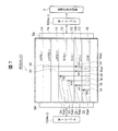
- FIG. 6 is a diagram showing an internal structure of the first relay box 40 constituting the first connecting portion 8 (No. 1) described above, and FIG. 7 shows the second connecting portion 8 (No. 2) described above. It is a figure which shows the internal structure of the 2nd relay box 42 to comprise.
- Reference numeral 54 shown in FIGS. 6 and 7 indicates a connector.
- each of the three power supply lines 12 is connected to the common ground line 16 by the first inspection wiring 18 in the first and second relay boxes 40 and 42, and Each of the three signal lines 14 is connected to the common ground line 16 by the second inspection wiring 20.
- the first and second inspection wirings 18 and 20 are provided with first and second diodes 22 and 24, respectively. During operation of the coating machine 1, current is prevented from flowing through the first and second inspection wires 18 and 20.
- reference numerals “CT”, “Dr. A”, and “Dr. B” denote power supplies (plus voltage) supplied to the high voltage generator 2.
- the symbol “ ⁇ AFB1” means a signal obtained by converting the current flowing through the high-voltage generator 2 into a voltage during operation of the electrostatic coating machine 1, and during operation of the electrostatic coating machine 1, the signal of “ ⁇ AFB1” is Returned to the control panel 4 with a positive voltage.
- the sign “kVFB” means a negative voltage signal obtained by stepping down the output of the high voltage generator 2, that is, a negative high voltage. For example, when the output of the high voltage generator 2 is ⁇ 90,000 volts, Minus 9 volts.
- the symbol “ ⁇ AFB2” means a signal obtained by converting the leakage current to the metal case surrounding the high voltage generator 2 into a negative voltage.
- An additional resistor R ad is connected in series with the diodes 22 and 24 to the first and second inspection wirings 18 and 20, respectively.
- FIGS. 6 and 7 show specific resistance values next to the additional resistance R ad , and the specific resistance values are determined based on experiments.
- the resistance value of the additional resistor R ad described above is set as follows. That is, the feedback voltage V a when a problem occurs in the first split cable 10 (No.1), all of the split cable 10 (No.1 ⁇ No.3) is higher than the feedback voltage when the normal becomes potential, and the second, third split cable 10 (No.2, No.3) feedback voltage V a when a problem occurs in that, all of the split cable 10 (No.1 ⁇ No.3) When the potential is lower than the normal feedback voltage and when a problem occurs in the second split cable 10 (No. 2) and when a problem occurs in the third split cable 10 (No. 3) Thus, the resistance value of the additional resistor R ad is set so that a clear difference appears in the feedback voltage V a .
- the electrostatic coating cable maintenance device of the embodiment is executed. Prior to this execution, the switch 32 described with reference to FIGS. 2 to 4 is turned off to cut off the grounding of the common ground wire 16, and a test voltage of, for example, several tens of volts is applied to the common ground wire 16. Is done.
- the electrostatic coating cable maintenance apparatus of the embodiment there is a problem with any one of the first to third divided cables 10 (No. 1 to No. 3).
- the feedback voltage V a all of the split cable 10 (No.1 ⁇ No.3) is different potential from the feedback voltage when the normal.
- the feedback voltage V a is the difference comes out by the problem to one of the split cable of the first to third split cable 10 (No.1 ⁇ No.3) has occurred.
- the defective divided cable identification means (high voltage controller IC) 30 identifies the first to third divided cables 10 (No. 1 to No. 3) where the problem has occurred, The display is displayed on the monitor of the control panel 4.
- the feedback voltage V As a feedback signal to a common earth wire 16 for example, when the inspection voltage plus several tens volts is applied, the feedback voltage V first to at differences in current value instead of a third split cable 10 (No.1 ⁇ No It is also possible to detect which of the split cables in .3) the problem has occurred.
- the operator immediately knows which split cable is abnormal by looking at the display on the monitor of the control panel 4, and immediately recovers the electrostatic coating cable 6 by replacing the split cable 10 in question. can do.
- the first and second diodes 22 and 24 can prevent the current from flowing through the first and second inspection wirings 18 and 20. Thus, the electrostatic coating machine 1 can be operated normally.
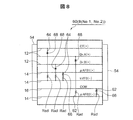
- FIG. 8 shows the internal structure of the relay box 60 included in the second embodiment.
- the relay box 60 constituting the first connecting portion 8 (No. 1) and the second connecting portion 8 (No. 2) has substantially the same configuration.
- the relay box 60 includes three power supply lines 12 that supply power (plus voltage) to the high voltage generator 2 during operation of the electrostatic coating machine 1, a common ground line 16, and three signal lines 14. Have.
- a positive voltage is fed back to the control panel 4 through the ⁇ AFB1 line
- a negative voltage is fed back to the control panel 4 through the kVFB line
- control is performed through the ⁇ AFB2 line. Negative voltage is fed back to panel 4.
- the three power supply lines 12 of positive voltage (in operation of the electrostatic coating machine 1), the signal line 14 of the ⁇ AFB1, and the common ground line 16 are negative voltage (in operation of the electrostatic coating machine 1).
- the third and fourth inspection wirings 62 and 64 are connected to either one of the two signal lines 14 of ⁇ AFB2 and kVFB. In the example of FIG. 8, the third inspection is performed on the Dr. A line that is the power supply line 12 and the common ground line 16 against the ⁇ AFB2 line that is the signal line 14 of the negative voltage (during operation of the electrostatic coating machine 1). Connected by the wiring 62, the CT line, the Dr.
- the fourth test wiring 64 is connected to the kVFB line which is the signal line 14 in operation.
- the CT power supply line 12 may be connected to the ⁇ AFB2 signal line 14, or the common ground line 16 may be connected to the kVFB signal line 14.
- the Dr. A power supply line 12 may be connected to the kVFB signal line 14, or the signal line 14 of the ⁇ AFB1 may be connected to the ⁇ AFB2 signal line 14.
- the third and fourth inspection wirings 62 and 64 have diodes 66 and 68 for preventing current from flowing through the third and fourth inspection wirings 62 and 64 during operation of the electrostatic coating machine 1.
- An additional resistor R ad is preferably connected in series with the diodes 66, 68.
- the resistance value of the additional resistor R ad connected to the third and fourth inspection wirings 62 and 64 is arbitrary. As described in the first embodiment, a problem occurs in the first divided cable 10 (No. 1), the second divided cable 10 (No. 2), or the third divided cable 10 (No. 3). In this case, the resistance value of the additional resistor R ad connected to the third and fourth inspection wirings 62 and 64 may be set so that a clear difference appears in the feedback voltage Va.
- the electrostatic coating cable maintenance apparatus is executed in order to detect an abnormality in the divided cable 8 or to identify an abnormal divided cable 8.
- the switch 32 described with reference to FIGS. 2 to 4 is turned off, the ground of the common ground wire 16 is cut off, and the negative voltage ⁇ AFB2 wire, For example, a positive test voltage of several tens of volts is applied to the two signal lines 14 of the kVFB line.
- any one of the first to third divided cables 10 (No. 1 to No. 3) is included as described above, including when the common ground wire 16 is about to break. If the problem in the divided cable has occurred, the feedback voltage V a, all of the split cable 10 (No.1 ⁇ No.3) is different potential from the feedback voltage when the normal. Then, the feedback voltage V a is the difference comes out by the problem to one of the split cable of the first to third split cable 10 (No.1 ⁇ No.3) has occurred. Using this difference, the defective divided cable identification means (high voltage controller IC) 30 identifies the first to third divided cables 10 (No. 1 to No. 3) where the problem has occurred, The display is displayed on the monitor of the control panel 4. Then, the operator immediately knows which divided cable is abnormal by looking at the display on the monitor of the control panel 4, and immediately replaces the divided cable 10 in question, so that the electrostatic coating cable 6 can be replaced at an early stage. Can be recovered.
- the defective divided cable identification means high voltage controller IC
- MyuAFB2 line as the feedback signal when two of the test voltage to the signal line 14 for example plus dozens volts kVFB line is applied, the current value in place of the feedback voltage V a Depending on the difference, it may be detected whether a problem has occurred in any of the first to third divided cables 10 (No. 1 to No. 3).
- FIG. 9 shows the internal structure of the relay box 70 included in the third embodiment.
- the relay box 70 constituting the first connecting portion 8 (No. 1) and the second connecting portion 8 (No. 2) has substantially the same configuration, and the relay box 70 included in the third embodiment is This is also a modification of the second embodiment (FIG. 8) described above.
- the Dr. B line 12 that is the power supply line 12 is connected to the kVFB line that is the signal line 14 of the negative voltage (during operation of the electrostatic coating machine 1) by the third inspection wiring 62.
- a diode 66 and preferably a resistor Rad are connected to the third inspection wiring 62.
- the CT line as the power supply line 12 is connected to the common ground line 16 via the fifth inspection line 72, and a diode 74 and preferably a resistor Rad are connected in series to the fifth inspection line 72.
- Other configurations are the same as those of the second embodiment (FIG. 8).
- the present invention teaches the following. That is, two wirings having a potential difference (during operation of the electrostatic coating machine 1) are connected by an inspection wiring having a diode, and a diode is interposed in the inspection wiring so that the electrostatic coating machine 1 is in operation. Prevents current from flowing through the inspection wiring. Therefore, if there is a potential difference between the potentials of the two wires having a positive potential during operation of the electrostatic coating machine 1, the two wires may be connected by an inspection wire having a diode.
- these two wires may be connected by an inspection wiring provided with a diode. Then, during the operation stop of the electrostatic coating machine 1, a voltage is applied to a wiring having a relatively low potential (during operation of the electrostatic coating machine 1) among the two wirings connected by the inspection wiring (to the diode). By applying a voltage in the forward direction), it is possible to detect a defect in each wiring.
- the present invention can be applied to rotary atomization type and spray type electrostatic coating machines.
- the present invention can also be applied to electrostatic coating machines for liquid paints and powder paints.
- the present invention can be applied to an electrostatic coating machine for conductive liquid paint (specifically, water-based paint) in addition to paint using thinner as a solvent.
Landscapes
- Physics & Mathematics (AREA)
- General Physics & Mathematics (AREA)
- Engineering & Computer Science (AREA)
- Manufacturing & Machinery (AREA)
- Health & Medical Sciences (AREA)
- Life Sciences & Earth Sciences (AREA)
- Chemical & Material Sciences (AREA)
- Analytical Chemistry (AREA)
- Biochemistry (AREA)
- General Health & Medical Sciences (AREA)
- Immunology (AREA)
- Pathology (AREA)
- Electrostatic Spraying Apparatus (AREA)
- Locating Faults (AREA)
- Details Or Accessories Of Spraying Plant Or Apparatus (AREA)
Priority Applications (3)
| Application Number | Priority Date | Filing Date | Title |
|---|---|---|---|
| CN201380010006.0A CN104126129B (zh) | 2012-02-20 | 2013-02-18 | 静电涂装电缆维护装置 |
| EP13751202.6A EP2818880A4 (fr) | 2012-02-20 | 2013-02-18 | Dispositif de maintenance de câble de revêtement électrostatique |
| US14/379,499 US9412500B2 (en) | 2012-02-20 | 2013-02-18 | Electrostatic coating cable maintenance device |
Applications Claiming Priority (4)
| Application Number | Priority Date | Filing Date | Title |
|---|---|---|---|
| JP2012034570 | 2012-02-20 | ||
| JP2012-034570 | 2012-02-20 | ||
| JP2012-209496 | 2012-09-24 | ||
| JP2012209496A JP5162723B1 (ja) | 2012-02-20 | 2012-09-24 | 静電塗装ケーブル保全装置 |
Publications (1)
| Publication Number | Publication Date |
|---|---|
| WO2013125478A1 true WO2013125478A1 (fr) | 2013-08-29 |
Family
ID=48013624
Family Applications (1)
| Application Number | Title | Priority Date | Filing Date |
|---|---|---|---|
| PCT/JP2013/053831 Ceased WO2013125478A1 (fr) | 2012-02-20 | 2013-02-18 | Dispositif de maintenance de câble de revêtement électrostatique |
Country Status (5)
| Country | Link |
|---|---|
| US (1) | US9412500B2 (fr) |
| EP (1) | EP2818880A4 (fr) |
| JP (1) | JP5162723B1 (fr) |
| CN (1) | CN104126129B (fr) |
| WO (1) | WO2013125478A1 (fr) |
Families Citing this family (3)
| Publication number | Priority date | Publication date | Assignee | Title |
|---|---|---|---|---|
| CN105158662A (zh) * | 2015-09-08 | 2015-12-16 | 国家电网公司 | 一种智能化电力电缆在线工频耐压试验装置 |
| CN109979371A (zh) * | 2019-04-15 | 2019-07-05 | 武汉华星光电技术有限公司 | 一种显示面板及装置 |
| CN112934503B (zh) * | 2021-01-27 | 2024-11-08 | 国网河北省电力有限公司电力科学研究院 | 一种用于互感器湿耐压试验的喷淋装置 |
Citations (5)
| Publication number | Priority date | Publication date | Assignee | Title |
|---|---|---|---|---|
| JPH01213039A (ja) * | 1988-02-22 | 1989-08-25 | Fujitsu Ltd | ケーブル断位置検出方式 |
| JPH0727811A (ja) * | 1993-07-14 | 1995-01-31 | Tatsuta Electric Wire & Cable Co Ltd | 混線・断線検知装置 |
| JPH10109054A (ja) | 1996-10-04 | 1998-04-28 | Nissan Motor Co Ltd | 静電塗装装置 |
| JP2002186884A (ja) | 2000-12-20 | 2002-07-02 | Abb Kk | 静電塗装装置 |
| JP2007029920A (ja) | 2005-07-29 | 2007-02-08 | Toyota Motor Corp | 静電塗装装置 |
Family Cites Families (11)
| Publication number | Priority date | Publication date | Assignee | Title |
|---|---|---|---|---|
| US3284704A (en) | 1962-04-10 | 1966-11-08 | Western Electric Co | Method for determining the magnitude of an open fault in one of a pair of current carrying conductors by measuring the voltage across a capacitance in series with the capacitance of said pair |
| CA1174302A (fr) * | 1982-02-24 | 1984-09-11 | Philip R. Staal | Bus numerique a faible puissance |
| CN2093044U (zh) * | 1990-11-27 | 1992-01-15 | 俞才富 | 双控式高压静电发生器 |
| CN2144029Y (zh) * | 1992-08-07 | 1993-10-20 | 中国石油天然气总公司工程技术研究所 | 静电粉末喷枪 |
| CN2198980Y (zh) * | 1994-11-16 | 1995-05-31 | 杜志源 | 双枪分体组合型喷塑主机装置 |
| KR0166509B1 (ko) * | 1995-12-29 | 1999-01-15 | 김주용 | 정전기 보호 회로 |
| JP4110510B2 (ja) * | 2002-03-08 | 2008-07-02 | 三菱電機株式会社 | 空気調和機の誤配線検出装置 |
| WO2005009621A1 (fr) * | 2003-07-24 | 2005-02-03 | Ransburg Industrial Finishing K.K. | Dispositif de peinture electrostatique |
| JP2005066410A (ja) * | 2003-08-20 | 2005-03-17 | Abb Kk | 静電塗装装置 |
| US20050194474A1 (en) * | 2004-03-03 | 2005-09-08 | Ransburg Industrial Finishing K.K. | Electrostatic atomizer for a painting robot |
| JP5508622B2 (ja) * | 2009-10-02 | 2014-06-04 | トヨタ自動車株式会社 | 高電圧発生装置の断線検出方法 |
-
2012
- 2012-09-24 JP JP2012209496A patent/JP5162723B1/ja active Active
-
2013
- 2013-02-18 EP EP13751202.6A patent/EP2818880A4/fr not_active Withdrawn
- 2013-02-18 US US14/379,499 patent/US9412500B2/en active Active
- 2013-02-18 WO PCT/JP2013/053831 patent/WO2013125478A1/fr not_active Ceased
- 2013-02-18 CN CN201380010006.0A patent/CN104126129B/zh not_active Expired - Fee Related
Patent Citations (5)
| Publication number | Priority date | Publication date | Assignee | Title |
|---|---|---|---|---|
| JPH01213039A (ja) * | 1988-02-22 | 1989-08-25 | Fujitsu Ltd | ケーブル断位置検出方式 |
| JPH0727811A (ja) * | 1993-07-14 | 1995-01-31 | Tatsuta Electric Wire & Cable Co Ltd | 混線・断線検知装置 |
| JPH10109054A (ja) | 1996-10-04 | 1998-04-28 | Nissan Motor Co Ltd | 静電塗装装置 |
| JP2002186884A (ja) | 2000-12-20 | 2002-07-02 | Abb Kk | 静電塗装装置 |
| JP2007029920A (ja) | 2005-07-29 | 2007-02-08 | Toyota Motor Corp | 静電塗装装置 |
Non-Patent Citations (1)
| Title |
|---|
| See also references of EP2818880A4 |
Also Published As
| Publication number | Publication date |
|---|---|
| US9412500B2 (en) | 2016-08-09 |
| CN104126129B (zh) | 2016-08-17 |
| JP5162723B1 (ja) | 2013-03-13 |
| EP2818880A1 (fr) | 2014-12-31 |
| US20150027370A1 (en) | 2015-01-29 |
| EP2818880A4 (fr) | 2015-12-09 |
| JP2013200294A (ja) | 2013-10-03 |
| CN104126129A (zh) | 2014-10-29 |
Similar Documents
| Publication | Publication Date | Title |
|---|---|---|
| TWI430845B (zh) | 資料管理之裝置及方法 | |
| JP5046390B2 (ja) | 除電装置 | |
| CN1816395B (zh) | 静电涂装装置 | |
| JP5162723B1 (ja) | 静電塗装ケーブル保全装置 | |
| US11135605B2 (en) | Electrostatic coater and electrostatic coating method | |
| JP4705818B2 (ja) | 静電塗装装置 | |
| KR20140011407A (ko) | 정전 도장 장치 | |
| CN102574138B (zh) | 用于高电压产生装置的检测断线的方法 | |
| JP7039211B2 (ja) | 複合ケーブルの断線予測装置及び静電コーティング装置用高電圧電源装置 | |
| AU2018248766B2 (en) | Power supply redundancy device for a display system | |
| KR102787047B1 (ko) | 배터리 모니터링 모듈 | |
| JP2018083148A (ja) | 静電塗装装置 | |
| JP6945433B2 (ja) | 静電塗装システムの自己診断方法 | |
| JP2012055048A (ja) | 接続部材外れ検知装置 | |
| JP7444621B2 (ja) | 帯電噴霧設備 | |
| US9597695B2 (en) | Electrostatic coating apparatus and electric conductivity check method | |
| JP2018079401A (ja) | 静電塗装用スプレーガン | |
| JP2006256348A (ja) | 直流電力ケーブル異常検出装置 | |
| JP2019063741A (ja) | 静電塗装装置 | |
| JPH0751167Y2 (ja) | 静電塗装用放電極 | |
| CN113945863A (zh) | 用于检测臂架线路信号的装置及臂架 | |
| JP2013238570A (ja) | 回路基板の検査装置 | |
| JP2003236414A (ja) | 静電塗装装置 | |
| AU2008200606A1 (en) | Electrostatic coating system | |
| JPH10309499A (ja) | 静電ガンのシールド線またはアース線断線検出方法 |
Legal Events
| Date | Code | Title | Description |
|---|---|---|---|
| 121 | Ep: the epo has been informed by wipo that ep was designated in this application |
Ref document number: 13751202 Country of ref document: EP Kind code of ref document: A1 |
|
| WWE | Wipo information: entry into national phase |
Ref document number: 14379499 Country of ref document: US |
|
| NENP | Non-entry into the national phase |
Ref country code: DE |
|
| REEP | Request for entry into the european phase |
Ref document number: 2013751202 Country of ref document: EP |
|
| WWE | Wipo information: entry into national phase |
Ref document number: 2013751202 Country of ref document: EP |