WO2013125521A1 - Dispositif d'éclairage - Google Patents
Dispositif d'éclairage Download PDFInfo
- Publication number
- WO2013125521A1 WO2013125521A1 PCT/JP2013/053992 JP2013053992W WO2013125521A1 WO 2013125521 A1 WO2013125521 A1 WO 2013125521A1 JP 2013053992 W JP2013053992 W JP 2013053992W WO 2013125521 A1 WO2013125521 A1 WO 2013125521A1
- Authority
- WO
- WIPO (PCT)
- Prior art keywords
- illumination
- color
- light
- point
- led element
- Prior art date
- Legal status (The legal status is an assumption and is not a legal conclusion. Google has not performed a legal analysis and makes no representation as to the accuracy of the status listed.)
- Ceased
Links
Images












Classifications
-
- H—ELECTRICITY
- H10—SEMICONDUCTOR DEVICES; ELECTRIC SOLID-STATE DEVICES NOT OTHERWISE PROVIDED FOR
- H10H—INORGANIC LIGHT-EMITTING SEMICONDUCTOR DEVICES HAVING POTENTIAL BARRIERS
- H10H20/00—Individual inorganic light-emitting semiconductor devices having potential barriers, e.g. light-emitting diodes [LED]
- H10H20/80—Constructional details
- H10H20/85—Packages
- H10H20/851—Wavelength conversion means
- H10H20/8511—Wavelength conversion means characterised by their material, e.g. binder
- H10H20/8512—Wavelength conversion materials
- H10H20/8513—Wavelength conversion materials having two or more wavelength conversion materials
-
- F—MECHANICAL ENGINEERING; LIGHTING; HEATING; WEAPONS; BLASTING
- F21—LIGHTING
- F21K—NON-ELECTRIC LIGHT SOURCES USING LUMINESCENCE; LIGHT SOURCES USING ELECTROCHEMILUMINESCENCE; LIGHT SOURCES USING CHARGES OF COMBUSTIBLE MATERIAL; LIGHT SOURCES USING SEMICONDUCTOR DEVICES AS LIGHT-GENERATING ELEMENTS; LIGHT SOURCES NOT OTHERWISE PROVIDED FOR
- F21K9/00—Light sources using semiconductor devices as light-generating elements, e.g. using light-emitting diodes [LED] or lasers
- F21K9/20—Light sources comprising attachment means
- F21K9/23—Retrofit light sources for lighting devices with a single fitting for each light source, e.g. for substitution of incandescent lamps with bayonet or threaded fittings
-
- F—MECHANICAL ENGINEERING; LIGHTING; HEATING; WEAPONS; BLASTING
- F21—LIGHTING
- F21V—FUNCTIONAL FEATURES OR DETAILS OF LIGHTING DEVICES OR SYSTEMS THEREOF; STRUCTURAL COMBINATIONS OF LIGHTING DEVICES WITH OTHER ARTICLES, NOT OTHERWISE PROVIDED FOR
- F21V3/00—Globes; Bowls; Cover glasses
-
- F—MECHANICAL ENGINEERING; LIGHTING; HEATING; WEAPONS; BLASTING
- F21—LIGHTING
- F21Y—INDEXING SCHEME ASSOCIATED WITH SUBCLASSES F21K, F21L, F21S and F21V, RELATING TO THE FORM OR THE KIND OF THE LIGHT SOURCES OR OF THE COLOUR OF THE LIGHT EMITTED
- F21Y2103/00—Elongate light sources, e.g. fluorescent tubes
- F21Y2103/10—Elongate light sources, e.g. fluorescent tubes comprising a linear array of point-like light-generating elements
-
- F—MECHANICAL ENGINEERING; LIGHTING; HEATING; WEAPONS; BLASTING
- F21—LIGHTING
- F21Y—INDEXING SCHEME ASSOCIATED WITH SUBCLASSES F21K, F21L, F21S and F21V, RELATING TO THE FORM OR THE KIND OF THE LIGHT SOURCES OR OF THE COLOUR OF THE LIGHT EMITTED
- F21Y2113/00—Combination of light sources
- F21Y2113/10—Combination of light sources of different colours
- F21Y2113/13—Combination of light sources of different colours comprising an assembly of point-like light sources
-
- F—MECHANICAL ENGINEERING; LIGHTING; HEATING; WEAPONS; BLASTING
- F21—LIGHTING
- F21Y—INDEXING SCHEME ASSOCIATED WITH SUBCLASSES F21K, F21L, F21S and F21V, RELATING TO THE FORM OR THE KIND OF THE LIGHT SOURCES OR OF THE COLOUR OF THE LIGHT EMITTED
- F21Y2115/00—Light-generating elements of semiconductor light sources
- F21Y2115/10—Light-emitting diodes [LED]
Definitions
- the present invention relates to a lighting device used for lighting in a living room.
- Patent Documents 1 and 2 Conventional illumination devices are disclosed in Patent Documents 1 and 2.
- the illumination device of Patent Document 1 illuminates the water in the bathtub by changing the light color in a preset change pattern. Thereby, the feeling of relaxation at the time of bathing can be heightened.
- the illumination device of Patent Document 2 illuminates by changing the illuminance according to the amount of sunlight. Thereby, it is possible to adjust the biological rhythm and to easily maintain the arousal level.
- the conventional lighting device does not contribute to the creation of an environment in which human stress can be eliminated, and there is a problem in that user stress cannot be eliminated. Further, the conventional lighting device has a problem that the fatigue level cannot be reduced when the user performs a predetermined work, and the fatigue level is large.
- the conventional lighting device does not contribute to the creation of a good sleep environment, and there is a problem that the user cannot obtain good sleep under any lighting.
- the conventional lighting device does not contribute to the creation of an environment that can reduce human fatigue, and the work efficiency of the work performed by the user cannot be increased under any lighting, There was a problem with low efficiency.
- the present invention has been made in view of the above points, and an object of the present invention is to provide an illumination device that can reduce human stress, improve comfort, and reduce fatigue during work. And Moreover, it aims at providing the illuminating device which can improve sleep efficiency and work efficiency.
- the area of 600 nm to 700 nm is 30 nm with respect to the area of 400 nm to 800 nm of the spectrum of illumination light.
- the area from 400 nm to 500 nm is 20% or less, and the spectrum of the illumination light has a maximum value between 600 nm and 700 nm, and the value of the spectrum at 550 nm with respect to the maximum value is It is characterized by being 50% or less.
- illumination is performed by emitting illumination light having the above spectrum by light emission of the LED element.
- the present invention provides an illumination device that emits illumination light by light emitted from an LED element and performs illumination in an area of 600 nm to 700 nm with respect to an area of 400 nm to 800 nm of the spectrum of illumination light. Is not less than 30% and not more than 70%, the area from 400 nm to 500 nm is not more than 20%, and the spectrum of the illumination light has a maximum value between 600 nm and 700 nm, and 500 nm to 600 nm with respect to the maximum value. The maximum value of the spectrum is 70% or less.
- illumination is performed by emitting illumination light having the above spectrum by light emission of the LED element. This improves the user's comfort and relaxed feelings during breaks and gatherings, and reduces the user's feeling of fatigue during work such as work or housework.
- the present invention is characterized in that, in the illumination device configured as described above, the area from 500 nm to 600 nm is 15% or more and 45% or less with respect to the area of the illumination light spectrum from 400 nm to 800 nm.
- the present invention is characterized in that a plurality of illumination lights having different spectra can be selected and emitted in the illumination device having the above configuration.
- the lighting device of the present invention has a point A1 (0.555, 0.394) on the xy chromaticity diagram defined by the International Lighting Commission by light emission of at least one LED element. Illumination within a region surrounded by the equal deviation line for the passing uniform color temperature line and the black body radiation locus and the equal deviation line for the constant color temperature line passing through the point B1 (0.419, 0.343) and the black body radiation locus. It is characterized by emitting colored illumination light.
- the illumination light of yellow red or orange pink color is emitted by the light emission of the LED element.
- the illumination color belongs to a color matching range represented by a Magdam ellipse 5-step centered on a point (0.499, 0.382) on the xy chromaticity diagram. It is characterized by color.
- the illumination color belongs to a color matching range represented by a Magdam ellipse 1-step centered on a point (0.499, 0.382) on the xy chromaticity diagram. It is characterized by color.
- the lighting device of the present invention has a point A2 (0.419, 0.343) on the xy chromaticity diagram determined by the International Lighting Commission by light emission of at least one LED element.
- the illumination light of the illumination color within the region surrounded by the straight line connecting the point B2 and the point C2 is emitted.
- illumination light of a color between yellow-red and yellowish white or between orange-pink and light pink is emitted by the light emission of the LED element.
- the sympathetic nervous system is prevented from advancing due to work loads such as work and housework, so that fatigue during work is reduced and work efficiency is improved.
- the illumination color belongs to a color matching range represented by a Magdam ellipse 5-step centered on a point (0.416, 0.377) on the xy chromaticity diagram. It is characterized by color.
- the illumination color belongs to a color matching range represented by a Magdam ellipse 1-step centered at a point (0.416, 0.377) on the xy chromaticity diagram. It is characterized by color.
- the lighting device of the present invention has a point A3 (0.350, 0.311) on the xy chromaticity diagram defined by the International Lighting Commission by light emission of at least one LED element.
- trajectory and the straight line which connects the point B3 and the point C3 is emitted.
- illumination light of a yellowish white or light pink illumination color is emitted by the light emission of the LED element.
- the excitement of the sympathetic nervous system due to stress can be suppressed. Therefore, when a person who feels stress spends in a room illuminated with the illumination color of the lighting device, the stress is reduced.
- the illumination color belongs to a color matching range expressed by a Magdam ellipse 5-step centered on a point (0.377, 0.362) on the xy chromaticity diagram. It is characterized by color.
- the illumination color belongs to a color matching range represented by a Magdam ellipse 1-step centered on a point (0.377, 0.362) on the xy chromaticity diagram. It is characterized by color.
- the present invention provides a color matching temperature line passing through a point A4 (0.555, 0.394) on the xy chromaticity diagram defined by the International Lighting Commission, by light emission of an LED element, and Illumination light of the illumination color in the first region surrounded by the equal deviation line for the black body radiation locus, the equal color temperature line passing through the point B4 (0.419, 0.343) and the equal deviation line for the black body radiation locus.
- the second illumination mode for emitting illumination light of the illumination color in the second region surrounded by the color matching temperature line passing through the point D4 (0.397, 0.370) and the straight line connecting the point C4 and the point D4
- the first illumination mode and the second illumination mode can be selected. It is characterized in that a Do operation unit.
- illumination in the first illumination mode or the second illumination mode is performed by the light emission of the LED element.
- Illumination light of yellow-red illumination color or orange-pink illumination color is emitted in the first illumination mode.
- illumination light of an illumination color between yellow-red and yellowish white or an illumination color between orange pink and light pink is emitted.
- the sympathetic nervous system is prevented from advancing due to work loads such as work and housework, so that fatigue during work is reduced and work efficiency is improved.
- the illumination color in the first illumination mode is represented by a Magdam ellipse 5-step centered at a point (0.499, 0.382) on the xy chromaticity diagram, etc. It is a color that belongs to a color range.
- the illumination color in the first illumination mode is represented by a Magdam ellipse 1-step centered on a point (0.499, 0.382) on the xy chromaticity diagram. It is a color that belongs to a color range.
- the illumination color in the second illumination mode is represented by a Magdam ellipse 5-step centered at a point (0.416, 0.377) on the xy chromaticity diagram, etc. It is a color that belongs to a color range.
- the illumination color in the second illumination mode is represented by a Magdam ellipse 1-step centered on a point (0.416, 0.377) on the xy chromaticity diagram. It is a color that belongs to a color range.
- the present invention is characterized in that the illumination device having the above-described configuration includes a cold color illumination mode for emitting daylight color, daylight white color or white color illumination light.
- the cold color illumination mode is performed by a predetermined operation, and daylight color, daylight white, or white illumination light is emitted.
- the present invention is characterized in that the illumination device having the above-described configuration is provided with a warm color illumination mode for emitting light bulb color or warm white illumination light.
- the warm color illumination mode is performed by a predetermined operation, and light bulb color or warm white illumination light is emitted.
- the illumination color is variable to a color between the cold color illumination mode and the warm color illumination mode
- the operation unit selects the first illumination mode.
- a second operation switch for selecting the second illumination mode, and a variable switch for stepwise varying the illumination color to a color between the cold color illumination mode and the warm color illumination mode.
- illumination in the first illumination mode is performed when the first operation switch of the operation unit is operated, and illumination in the second illumination mode is performed when the second operation switch is operated.
- the illumination color is changed stepwise from the illumination color in the cold color illumination mode to the illumination color in the warm color illumination mode.
- the present invention makes the illumination color variable between the cold color illumination mode and the warm color illumination mode, and makes the illumination color variable in the first region and the second region, A first variable switch for changing the illumination color to a color in the first area and the second area; and a second variable switch for changing the illumination color to a color between the cold color illumination mode and the warm color illumination mode. It is characterized by having.
- the first area and the second area are continuous on the xy chromaticity diagram.
- the first illumination mode and the second illumination mode are performed by changing the illumination color of the first region stepwise from the illumination color of the first region by the operation of the first variable switch.
- illumination is performed by changing stepwise from the illumination color in the cold color illumination mode to the illumination color in the warm color illumination mode.
- the present invention is characterized in that the illumination device having the above-described configuration is provided with a warm color illumination mode for emitting light bulb color or warm white illumination light.
- the operation unit selects the first illumination mode, and the second illumination mode.
- a second operation switch for selecting is performed. According to this configuration, illumination in the first illumination mode is performed when the first operation switch of the operation unit is operated, and illumination in the second illumination mode is performed when the second operation switch is operated.
- the illumination device having the above-described configuration, only the first illumination mode and the second illumination mode having different illumination colors are provided, the illumination color is variable in the first area and the second area, and the operation unit includes It has a variable switch that changes the illumination color step by step.
- the first area and the second area are continuous on the xy chromaticity diagram.
- the first illumination mode and the second illumination mode are performed stepwise by changing the illumination color of the first region from the illumination color of the first region by operating the variable switch.
- the present invention is characterized in that the lighting device having the above-described configuration includes a plurality of the LED elements, and each of the LED elements emits light in a different color. According to this configuration, the plurality of LED elements emit light in different colors and are mixed, and the illumination color in the region or illumination light having a predetermined spectrum is emitted.
- the present invention is characterized in that the illumination device having the above-described configuration includes the LED element that emits a light bulb color, the LED element that emits red light, and the LED element that emits white light. According to this configuration, the color of the light bulb emitted from the plurality of LED elements, red and white are mixed, and the illumination color within the region or illumination light having a predetermined spectrum is emitted.
- the LED element that emits light bulb color is represented by a Magdam ellipse 5-step centered at a point (0.445, 0.408) on the xy chromaticity diagram.
- the maximum value of the wavelength of the LED element that emits red light is characterized by being 575 nm to 780 nm.
- the present invention is characterized in that, in the illumination device configured as described above, the color of the illumination light is variable between the color in the region and white. According to this configuration, in addition to emitting illumination light of the illumination color in the region, the illumination device emits illumination light by mixing the illumination color with a color between the color in the region and white. .
- the present invention is characterized in that the illumination device having the above-described configuration includes a phosphor that converts the emitted light of the LED element into a different wavelength. According to this configuration, the emitted light of the LED element and the fluorescent light from the phosphor are mixed, and the illumination color in the region or the illumination light of a predetermined spectrum is emitted.
- the LED element that emits blue light the phosphor that converts blue light into light bulb light, the phosphor that converts blue light into red light, and blue And a phosphor that converts light into yellow light.
- the light emitted from the LED element and the yellow fluorescence by the phosphor are mixed to form white light.
- the white light, red fluorescence by the phosphor, and light bulb color fluorescence by the phosphor are mixed to emit illumination color within the region or illumination light of a predetermined spectrum.
- the area from 600 nm to 700 nm is not less than 30% and not more than 70%, the area from 400 nm to 500 nm is not more than 20%, and the spectrum of illumination light is 600 nm.
- the LED element emits illumination light having a maximum value in the range of from 700 to 700 nm and emitting illumination light having a spectrum value of 550 nm of 50% or less with respect to the maximum value.
- illumination light is emitted by the light emission of the LED element, illumination can be performed without including ultraviolet rays that have a chemical adverse effect on the human body and infrared rays that have a thermal adverse effect.
- the area from 600 nm to 700 nm is 30% or more and 70% or less and the area from 400 nm to 500 nm is 20% or less with respect to the area from 400 nm to 800 nm in the spectrum.
- illumination light is emitted by the light emission of the LED element, illumination can be performed without including ultraviolet rays that have a chemical adverse effect on the human body and infrared rays that have a thermal adverse effect.
- the illuminating device includes the isochromatic temperature line passing through the point A1 (0.555, 0.394) on the xy chromaticity diagram, the equal deviation line with respect to the black body radiation locus, and the point B1 ( 0.419, 0.343) is illuminated by the light emission of the LED element in the region surrounded by the equal color temperature line passing through 0.419, 0.343) and the equal deviation line with respect to the black body radiation locus.
- the illumination light of the illumination color in the region is emitted by the light emission of the LED element, it is possible to perform illumination without including ultraviolet rays that have a chemical adverse effect on the human body and infrared rays that have a thermal adverse effect. it can.
- the illuminating device has an isodeviation line with respect to the isochromatic temperature line passing through the point A2 (0.419, 0.343) and the black body radiation locus on the xy chromaticity diagram, and the point B2.
- the work efficiency of the work performed by the user can be improved.
- the illumination light of the illumination color in the region is emitted by the light emission of the LED element, it is possible to perform illumination without including ultraviolet rays that have a chemical adverse effect on the human body and infrared rays that have a thermal adverse effect. it can.
- the illuminating device has an isodeviation line with respect to the isochromatic temperature line passing through the point A3 (0.350, 0.311) and the black body radiation locus on the xy chromaticity diagram, and the point B3.
- the illumination light of the illumination color in the region is emitted by the light emission of the LED element, it is possible to perform illumination without including ultraviolet rays that have a chemical adverse effect on the human body and infrared rays that have a thermal adverse effect. it can.
- the second illumination mode for emitting illumination light of the illumination color in the second region surrounded by the straight line connecting the point C4 and the point D4 is performed by light emission of the LED element.
- the first illumination mode can provide good quality sleep such as shortening the sleep latency and improving sleep efficiency, and reduce the accumulated feeling of fatigue.
- the work efficiency of the work performed by the user in the second illumination mode can be improved.
- the illumination light of the first region and the second region is emitted by the light emitted from the LED element, the illumination does not include ultraviolet rays that have a chemical adverse effect on the human body or infrared rays that have a thermal adverse effect. It can be performed.
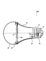
- the lighting device 100 has a cap 32 at one end and is configured as a light bulb that can be attached to a lighting fixture.
- An LED module 37 having an LED element 36 is disposed inside the lighting device 100.
- the LED module 37 is formed by mounting the LED element 36 on the light source substrate 37b.
- the outer shape of the lighting device 100 is formed by a base 32, a support member 33, a heat sink 35, and a transmission cover 39.
- the base 32 is formed in, for example, an E26 type and is screwed into a socket supplied with power from a commercial power source.
- the support member 33 is formed in a cylindrical shape by an insulator such as a resin molded product, and the screw portion 33 a is screwed to the inner surface of the base 32 and attached to the base 32.
- a plurality of engaging claws 33 d are provided at one end of the support member 33.
- the heat sink 35 is formed in a cylindrical shape having a substantially conical surface with a metal such as aluminum, and is attached by engaging one end with an engaging claw 33 d of the support member 33.
- the other end of the heat sink 35 is covered with an installation surface 35a, and an LED module 37 is installed on the installation surface 35a via a heat dissipation sheet 35c made of a flexible high heat conductor. Thereby, the heat generated by the LED element 36 is radiated through the heat radiating sheet 35 c and the heat sink 35.
- a resin module fixing portion 38 is disposed on the installation surface 35a.
- the module fixing portion 38 has a through hole 38a at the center, and the engaging claws 38b are engaged and attached to a plurality of engaging holes 35b provided on the installation surface 35a.
- the LED module 37 and the heat dissipation sheet 35c are sandwiched between the installation surface 35a and the module fixing portion 38 in a state where the LED element 36 is exposed from the through hole 38a.
- the transmission cover 39 is formed in a dome shape and is screwed onto the peripheral portion of the module fixing portion 38.
- the transmission cover 39 is formed of a resin that diffuses and transmits the light emitted from the LED element 36.
- the control board 34 inserted through the support member 33 and the heat sink 35 is disposed.
- the control board 34 has a power supply circuit (not shown) and the like, converts AC power supplied to the base 32 into DC power, and supplies it to the LED element 36.
- control board 34 is buried in a filler 40 such as an ultraviolet curable resin or an epoxy resin filled in the base 32.
- a filler 40 such as an ultraviolet curable resin or an epoxy resin filled in the base 32.
- the columnar portion 33b is erected on the end surface of the support member 33 on the LED element 36 side so as to face each other.
- a groove portion (not shown) that extends in the axial direction and fits the control board 34 is provided on the inner peripheral surface of the columnar portion 33b.
- the control board 34 is bonded by filling an adhesive such as an ultraviolet curable resin or an epoxy resin in the gap between the control board 34 and the groove.
- the illumination device 100 configured as described above, when the base 32 is connected to a commercial power supply via a socket, DC power is supplied from the control board 34 to the LED element 36. Thereby, the LED element 36 emits light. The light from the LED element 36 is diffused and transmitted through the transmission cover 39, and the illumination light is emitted to illuminate the interior of the room.
- the spectrum of the illumination light of the illumination device 100 is such that the area from 600 nm to 700 nm is 30% or more and 70% or less, and the area from 400 nm to 500 nm is 20% or less with respect to the area from 400 nm to 800 nm. .
- the maximum value of the spectrum of illumination light is included in the range of wavelengths from 600 nm to 700 nm.
- the value of the spectrum of the illumination light having a wavelength of 550 nm is 50% or less of the maximum value of the spectrum having a wavelength in the range of 600 nm to 700 nm.
- the user's comfort and relaxation can be improved, and the number of trials, correct answer rate, etc.
- the work efficiency can be improved.
- the area from 600 nm to 700 nm is 30% to 70% and the area from 400 nm to 500 nm is 20% or less with respect to the area from 400 nm to 800 nm of the spectrum
- the spectrum of the illumination light is Illumination for emitting illumination light having a maximum value between 600 nm and 700 nm and having a spectrum value of 550 nm of 50% or less with respect to the maximum value is performed by light emission of the LED element 36.
- fluorescent lamps may leak ultraviolet rays
- incandescent bulbs are said to emit a large amount of infrared rays.
- Ultraviolet rays may have a chemical adverse effect on living organisms and indoor facilities, and infrared rays may have a thermal adverse effect.
- the illumination is performed by the light emission of the LED element 36 that hardly contains ultraviolet rays or infrared rays, the illumination device 100 with less adverse effects on the human body can be provided.
- the lighting device 100 is configured as a light bulb that can be attached to a lighting fixture, but may be a straight tube type or a circular tube type lighting device that is attached to the lighting fixture. Further, a plurality of LED elements and a control circuit for controlling them may be provided so that the light can be adjusted by operating an external switch.
- FIG. 3 is an overall perspective view of the lighting device as viewed from below.
- the lighting device 200 constitutes a ceiling light that is a lighting fixture, and is attached to an indoor ceiling surface.
- the illuminating device 200 may be a lighting fixture attached to a side wall in the room.
- the lighting device 200 includes a substantially plate-like main body 1 having a circular shape fixed to an indoor ceiling surface located above and a remote controller (not shown), and illuminates a lower indoor floor surface.
- the main body 1 includes a light source substrate 2, a reflecting plate 3, a frame 4, and an illumination control unit 5.
- the light source substrate 2 is formed in a rectangular shape in plan view, and is attached to the lower surface of the main body 1 via the frame 4 while standing upright or substantially perpendicular to the main body 1.
- a plurality of LED (Light Emitting Diode) elements (6a, 6b, 6c, see FIG. 4) are provided on the surface of the light source substrate 2.
- the white LED element 6a, the light bulb color LED element 6b, and the red LED element 6c may be collectively referred to as the LED element 6.
- the reflecting plate 3 is provided on the lower surface of the main body 1 as shown in FIG.
- the reflector 3 reflects the light emitted from the LED element 6 toward the floor surface, and the reflected light irradiates the floor surface. Thereby, the illumination intensity of the whole floor surface is obtained.
- the frame 4 has a regular polygon (for example, a regular octagon in FIG. 3) or a substantially regular polygon with the central axis extending in the vertical direction of the main body 1 as the center.
- the light source substrate 2 is attached to each side of the regular octagon of the frame 4 so that the light emission direction of the LED elements 6 faces radially outward.
- the LED element 6 emits light radially outward with respect to the center of the main body 1, and the light is reflected by the reflector 3.
- the illumination control unit 5 has a control board (not shown) including a power circuit (see FIG. 5) and the like, and is arranged on the inner side in the radial direction of the frame 4.
- the illumination control unit 5 is connected to a power connector (not shown) provided at the central portion of the main body 1 in the radial direction, and receives power from an external power source through the power connector.
- the illumination control part 5 supplies the electric power to the LED element 6, and makes the LED element 6 light-emit.
- a diffusing lens or a cover may be provided.
- the diffusion lens is attached to the front surface of the light emitting surface of the light source substrate 2 and uniformly diffuses the light emitted from the LED element 6.
- the cover has a circular shape that is substantially the same diameter as the outer diameter of the main body 1 and is fitted and held on the peripheral edge of the main body 1 to cover the entire lower surface of the main body 1. The cover further diffuses the light emitted from the LED element 6 and prevents a person from directly viewing the light.
- the LED device 6 does not directly illuminate the floor surface in the lighting device 200, even when a person faces the ceiling and looks directly at the illumination, the light of the LED element 6 is difficult to be directly inserted into the human eye. The burden can be reduced.
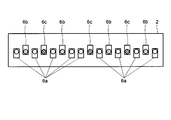
- FIG. 4 shows a plan view of the light source substrate 2.
- a plurality of white LED elements 6a, light bulb color LED elements 6b, and red LED elements 6c are arranged, for example, in substantially horizontal rows.
- nine white LED elements 6a, four bulb-color LED elements 6b, and three red LED elements 6c are mounted on the light source substrate 2.
- the arrangement and interval of the LED elements 6 affect the uniformity of light emission to the reflector 3.
- the illumination quality of the illumination device 200 decreases.
- each LED element 6 emits light in a different color and performs toning with the combination thereof, non-uniform illuminance causes color unevenness and greatly affects the illumination quality of the illumination device 200. Therefore, when using the several LED element 6 which light-emits with a different color, the arrangement
- the white LED element 6c emits white light.
- the light bulb color LED element 6b emits light in a light bulb color. More specifically, the light bulb color LED element 6b is a color belonging to a color matching range represented by a Magdam ellipse 5-step centered on a point (0.445, 0.408) on an xy chromaticity diagram determined by the International Lighting Commission. Flashes on.
- the red LED element 6c emits red light. More specifically, the red LED element 6c emits light in a color having a maximum wavelength value of 575 nm to 780 nm.
- the color of the light bulb color LED element 6b is a color belonging to the color matching range represented by the Magdam ellipse 5-step centered on the point (0.445, 0.408) on the xy chromaticity diagram as described above. And there is some variation. Further, the color of the red LED element 6c also has a certain range with the maximum value of the wavelength being 575 nm to 780 nm as described above.
- a plurality of white LED elements 6a, a plurality of light bulb color LED elements 6b, and a plurality of red LED elements 6c can be mounted on the light source substrate 2 to suppress variations in coloring.
- a plurality of LED elements having different colors may be configured as one LED element.
- FIG. 5 is a block diagram showing the configuration of the illumination device 200
- FIG. 6 is an explanatory diagram showing the configuration of the LED element light emitting mechanism of the illumination device 200.
- the illumination control unit 5 includes a power supply circuit 10 as shown in FIG.
- the power supply circuit 10 receives power supplied from an AC power supply (AC input, 100 V), converts it to a DC voltage, and supplies power to each part of the lighting device 200.
- the power supply circuit 10 is shown as supplying power to the control power supply circuit 14 and the light source substrate 2 as an example.
- the present invention is not limited to this and is also necessary for other parts. It is assumed that power is supplied.
- the illumination control unit 5 includes a CPU (Central Processing Unit) 11, a memory 12, a PWM (Pulse Width Modulation) control circuit 13, a control power supply circuit 14, and an input unit 15. Yes.
- the CPU 11, the memory 12, and the PWM control circuit 13 are configured by a microcomputer.
- the CPU 11 is connected to each unit and instructs an operation necessary for controlling the entire lighting device 200.
- the CPU 11 is connected to a switch (not shown) wirelessly or by wire, and receives an instruction input in response to an operation of the switch at the input unit 15.
- the memory 12 stores various programs for controlling the lighting device 200, initial values, and the like, and is also used as a working memory for the CPU 11.
- the PWM control circuit 13 generates a PWM pulse necessary for driving the LED element 6 in accordance with an instruction from the CPU 11.
- the control power supply circuit 14 adjusts the voltage of the power supplied from the power supply circuit 10 to supply it to the CPU 11.
- the light source substrate 2 is provided with the three types of LED elements 6 including the white LED element 6a, the light bulb color LED element 6b, and the red LED element 6c, and the FET (Field for driving each LED element 6). Effect Transistor) switches 21, 22, and 23 are arranged.
- FIG. 5 shows a white LED element 6a, a light bulb color LED element 6b, and a red LED element 6c, respectively.
- the white LED element 6a and the light bulb color LED are drawn.
- a plurality of elements 6b and red LED elements 6c are provided.
- the FET switches 21, 22, and 23 may be in the PWM control circuit 13.
- the CPU 11 instructs the PWM control circuit 13 to generate and output PWM pulses M1, M2, and M3 for emitting at least one of the white LED element 6a, the light bulb color LED element 6b, and the red LED element 6c.
- the white LED element 6 a, the light bulb color LED element 6 b and the red LED element 6 c are supplied with necessary power from the power supply circuit 10.
- FET switches 21, 22, and 23 are provided between the white LED element 6a, the light bulb color LED element 6b, the red LED element 6c, and the ground voltage GND, respectively.
- the FET switches 21, 22, and 23 are turned on and off, so that current is supplied to and cut off from the white LED element 6a, the light bulb color LED element 6b, and the red LED element 6c. .
- the white LED element 6a, the light bulb color LED element 6b, and the red LED element 6c each of these LED elements 6 emits light.
- the structure which light-emits white LED element 6a, light bulb color LED element 6b, and red LED element 6c was demonstrated, it is the same also when the other LED element is provided with two or more.
- the CPU11 judges the timing which performs illumination by running a program according to the operation signal inputted in input part 15.
- the lighting timing may be determined by pressing a switch (not shown).
- the timing for lighting may be determined when it is detected that a preset time has been reached or a preset time has passed by a timer or the like (not shown).
- the CPU 11 instructs the PWM control circuit 13 so that the white LED element 6a, the light bulb color LED element 6b, and the red LED element 6c emit light with a predetermined intensity.
- the PWM control circuit 13 outputs PWM pulses M1, M2, and M3 in accordance with an instruction from the CPU 11, and adjusts the color to a predetermined illumination color.
- the spectrum of the illumination light of the illumination device 200 is such that the area from 600 nm to 700 nm is 30% or more and 70% or less with respect to the area from 400 nm to 800 nm, and the area from 400 nm to 500 nm. Is 20% or less.
- the maximum value of the spectrum of illumination light is included in the range of wavelengths from 600 nm to 700 nm.
- the value of the spectrum of the illumination light having a wavelength of 550 nm is 50% or less of the maximum value of the spectrum having the wavelength in the range of 600 nm to 700 nm.
- the user's comfort and relaxation can be improved, and the number of trials, correct answer rate, etc.
- the work efficiency can be improved.
- the area from 600 nm to 700 nm is 30% to 70% and the area from 400 nm to 500 nm is 20% or less with respect to the area from 400 nm to 800 nm of the spectrum
- the spectrum of the illumination light is Illumination for emitting illumination light having a maximum value between 600 nm and 700 nm and having a spectrum value of 550 nm of 50% or less with respect to the maximum value is performed by light emission of the LED element 6.
- the illuminating device 200 with few bad influences with respect to a human body can be provided.
- the white LED element 6a, the light bulb color LED element 6b, and the red LED element 6c that are colored in different colors are included, illumination light having a spectrum in the above range can be easily emitted.
- the illumination color may be adjusted by the LED elements 6 having other emission colors.
- the LED elements 6 having other emission colors For example, a plurality of LED elements that respectively emit blue, green, and red light may be provided.
- an LED element and a phosphor that converts the emitted light of the LED element into different wavelengths may be provided.
- a plurality of LED elements that emit blue light and phosphors that convert blue light into a light bulb color, red, and yellow may be provided corresponding to each LED element.
- White light is formed by blue light and yellow light, and the illumination color can be adjusted by white, light bulb color, and red light in the same manner as described above.
- the CPU 11 illustrated in FIG. 5 determines the timing of lighting by executing a program according to the operation signal input from the input unit 15. For example, the lighting timing may be determined by pressing a switch (not shown). Alternatively, the timing for lighting may be determined when it is detected that a preset time has been reached or a preset time has passed by a timer or the like (not shown).
- the CPU 11 instructs the PWM control circuit 13 so that the white LED element 6a, the light bulb color LED element 6b, and the red LED element 6c emit light with a predetermined intensity.
- the PWM control circuit 13 outputs PWM pulses M1, M2, and M3 in accordance with an instruction from the CPU 11, and adjusts the color to a predetermined illumination color.
- the spectrum of the illumination light of the illumination device 200 is such that the area from 600 nm to 700 nm is 30% or more and 70% or less, and the area from 400 nm to 500 nm is 20% or less with respect to the area of wavelength from 400 nm to 800 nm. .
- the maximum value of the spectrum of illumination light is included in the range of wavelengths from 600 nm to 700 nm.
- the maximum value of the spectrum in the range where the wavelength of the illumination light is 500 nm to 600 nm is 70% or less of the maximum value of the spectrum in the range of the wavelength from 600 nm to 700 nm.
- the user's comfort and relaxed feeling can be improved by emitting the illumination light having the above spectrum to the living room during breaks or during a meeting.
- the area from 600 nm to 700 nm is 30% to 70% and the area from 400 nm to 500 nm is 20% or less with respect to the area from 400 nm to 800 nm of the spectrum
- the spectrum of the illumination light is
- the LED element emits light that emits illumination light having a maximum value between 600 nm and 700 nm, and the maximum value of the spectrum from 500 nm to 600 nm is 70% or less of the maximum value.
- fluorescent lamps may leak ultraviolet rays, and incandescent bulbs are said to emit a large amount of infrared rays.
- Ultraviolet rays may have a chemical adverse effect on living organisms and indoor facilities, and infrared rays may have a thermal adverse effect.
- the illumination is performed by the light emission of the LED element 6 that hardly contains ultraviolet rays or infrared rays, the illumination device 200 with less adverse effects on the human body can be provided.
- improvement of work efficiency and sleep efficiency can be aimed at according to a user's state.
- the white LED element 6a, the light bulb color LED element 6b, and the red LED element 6c that are colored in different colors are included, illumination light having a spectrum in the above range can be easily emitted.
- the illumination color may be adjusted by the LED elements 6 having other emission colors.
- the LED elements 6 having other emission colors For example, a plurality of LED elements that respectively emit blue, green, and red light may be provided.
- a phosphor that converts the emitted light of the LED element and the LED element into different wavelengths may be provided.
- a plurality of LED elements that emit blue light and phosphors that convert blue light into a light bulb color, red, and yellow may be provided corresponding to each LED element.
- White light is formed by blue light and yellow light, and the illumination color can be adjusted by white, light bulb color, and red light in the same manner as described above.
- the lighting device attached to the room by the lighting device 200 is configured, the lighting device may be a light bulb or the like attached to the lighting device.
- each LED element 6 emits light with a light amount according to an operation of a remote controller (not shown) by the light emitting mechanism shown in FIG. Is emitted.
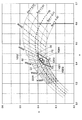
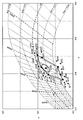
- FIG. 7 shows a detailed view of the vicinity of the blackbody radiation locus V0 in the xy chromaticity diagram determined by the International Commission on Illumination.
- the illumination device 200 has, on the xy chromaticity diagram, an equal deviation line V101 for the color matching temperature line W101 passing through the point A1 (0.555, 0.394) and the black body radiation locus V0, and a point B1.
- the illumination light of the illumination color in the region S101 surrounded by the equal color temperature line W102 passing through (0.419, 0.343) and the equal deviation line V102 with respect to the black body radiation locus V0 is emitted.
- the chromaticity coordinates of the intersection C1 between the equal color temperature line W101 and the equal deviation line V102 are (0.510, 0.340), and the chromaticity of the intersection D1 between the equal color temperature line W102 and the equal deviation line V101.
- the coordinates are (0.453, 0.401). Accordingly, the region S101 is surrounded by the points A1, C1, B1, and D1 in the clockwise direction in the drawing.
- the area S101 is yellowish red or orange pink.
- the illuminating device 200 emits illumination light of yellow-red illumination color or orange-pink illumination color. Thereby, it is possible to make the parasympathetic nerve superior without disturbing the melatonin secretion of the user in the room.
- the lighting device 200 can improve sleep efficiency by shortening the sleep latency at bedtime and extending the sleeping time.
- the lighting device 200 can relax and heal at the time of a break or a gathering, and can reduce the accumulated feeling of fatigue.
- the lighting device 200 having the above-described configuration has a plurality of lighting modes.
- a desired lighting mode is selected by the remote controller.
- the CPU 11 instructs the PWM control circuit 13 so that the white LED element 6a, the light bulb color LED element 6b, and the red LED element 6c emit light with a predetermined intensity.
- the PWM control circuit 13 outputs PWM pulses M1, M2, and M3 according to instructions from the CPU 11, and performs color adjustment so that the illumination color corresponds to each illumination mode.
- the lighting device 200 emits light from the LED element 6, and the color matching temperature line W101 passing through the point A1 (0.555, 0.394) on the xy chromaticity diagram determined by the International Lighting Commission and black Illumination color in the region S101 surrounded by the equal deviation line V101 with respect to the body radiation locus V0, the equal color temperature line W102 passing through the point B1 (0.419, 0.343), and the equal deviation line V102 with respect to the black body radiation locus V0.
- the illumination light is emitted.
- fluorescent lamps may leak ultraviolet rays, and incandescent bulbs are said to emit a lot of infrared rays.
- Ultraviolet rays may have a chemical adverse effect on living organisms and indoor facilities, and infrared rays may have a thermal adverse effect.
- the illumination is performed by the light emission of the LED element 6 that hardly contains ultraviolet rays or infrared rays, the illumination device 200 with less adverse effects on the human body can be provided.
- the white LED element 6a, the light bulb color LED element 6b, and the red LED element 6c that are colored in different colors are provided, the illumination light of the illumination color in the region S101 can be easily emitted.
- the illumination color in the region S101 may be adjusted by the LED elements 6 having other emission colors.
- LED elements that respectively emit blue, green, and red light may be provided.
- the color of the illumination light may be variable between the color in the region S101 and white.
- the illumination device 200 can emit illumination light of the illumination color in the area S101, and in addition, the illumination color is mixed with the color between the color in the area S101 and white to emit illumination light. It is possible to emit.
- a phosphor that converts the emitted light of the LED element and the LED element into different wavelengths may be provided.
- White light is formed by blue light and yellow light, and the illumination color in the region S101 can be dimmed by white, light bulb color, and red light in the same manner as described above.
- the lighting device attached to the room by the lighting device 200 is configured, the lighting device may be a light bulb or the like attached to the lighting device.
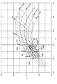
- FIG. 8 shows a detailed view of the vicinity of the black body radiation locus V0 of the xy chromaticity diagram determined by the International Commission on Illumination.
- a uniform color temperature line group and a uniform deviation line group with respect to the black body radiation locus V0 are described in an overlapping manner.
- the illuminating device 200 according to the fifth embodiment has a color deviation line V201 with respect to the color matching temperature line W201 passing through the point A2 (0.419, 0.343) and the black body radiation locus V0 on the xy chromaticity diagram, and a point B2.
- the illumination light in the region S201 surrounded by the connecting straight line is emitted.
- the chromaticity coordinate of the intersection D2 between the equal color temperature line W201 and the equal deviation line V202 is (0.453, 0.401), and the chromaticity of the intersection E2 between the equal color temperature line W202 and the equal deviation line V201.
- the coordinates are (0.383, 0.329). Accordingly, the region S201 is surrounded by a point A2, a point E2, a point C2, a point B2, and a point D2 in the clockwise direction in the drawing.
- the region S201 has a color between yellow-red and yellowish white, or a color between orange pink and light pink. For this reason, the illuminating device 200 emits the illumination light of the illumination color of the color between yellow red and yellowish white or the color between orange pink and light pink. As a result, the fatigue of the sympathetic nervous system due to work loads such as business and housework is suppressed and the feeling of fatigue is reduced. As a result, the lighting device 200 can suppress a reduction in work efficiency during long-time work, and can improve work efficiency.
- the lighting device 200 having the above-described configuration has a plurality of lighting modes.
- a desired lighting mode is selected by the remote controller.
- the CPU 11 instructs the PWM control circuit 13 so that the white LED element 6a, the light bulb color LED element 6b, and the red LED element 6c emit light with a predetermined intensity.
- the PWM control circuit 13 outputs PWM pulses M1, M2, and M3 according to instructions from the CPU 11, and performs color adjustment so that the illumination color corresponds to each illumination mode.
- the illumination device 200 emits light from the LED element 6, and the color matching temperature line W201 passing through the point A2 (0.419, 0.343) on the xy chromaticity diagram determined by the International Lighting Commission and An equal deviation line V201 with respect to the blackbody radiation locus V0, an equal deviation line V202 with respect to the blackbody radiation locus V0 passing through the point B2 (0.418, 0.390), and a point C2 (0.397, 0.370) are passed.
- the illumination light of the illumination color in the region S201 surrounded by the color matching temperature line W202 and the straight line connecting the point B2 and the point C2 is emitted.
- fluorescent lamps may leak ultraviolet rays, and incandescent bulbs are said to emit a lot of infrared rays.
- Ultraviolet rays may have a chemical adverse effect on living organisms and indoor facilities, and infrared rays may have a thermal adverse effect.
- the illumination is performed by the light emission of the LED element 6 that hardly contains ultraviolet rays or infrared rays, the illumination device 200 with less adverse effects on the human body can be provided.
- the illumination light of the illumination color in the region S201 can be easily emitted.
- the illumination color in the region S201 may be adjusted by the LED elements 6 having other emission colors.
- LED elements that respectively emit blue, green, and red light may be provided.
- the color of the illumination light may be variable between the color in the region S201 and white.
- the illumination device 200 mixes the illumination color with the color between the color in the area S201 and the white color and emits illumination light. It is possible to emit.
- a phosphor that converts the emitted light of the LED element and the LED element into different wavelengths may be provided.
- White light is formed by blue light and yellow light, and the illumination color in the region S201 can be dimmed by white, light bulb color, and red light in the same manner as described above.
- the lighting device attached to the room by the lighting device 200 is configured, the lighting device may be a light bulb or the like attached to the lighting device.
- FIG. 9 shows a detailed view of the vicinity of the blackbody radiation locus V0 in the xy chromaticity diagram determined by the International Commission on Illumination.
- the lighting device 200 includes a color matching temperature line W301 and an equal deviation line V301 passing through a point A3 (0.350, 0.311), and a point B3 (0.397, 0) on the xy chromaticity diagram. .370), a uniform color temperature line W302 passing through the point C3 (0.388, 0.378), and an illumination color in the region S301 surrounded by a straight line connecting the point B3 and the point C3. The illumination light is emitted.
- the chromaticity coordinates of the intersection D3 between the equal color temperature line W302 and the equal deviation line V301 are (0.383, 0.329), and the chromaticity at the intersection E3 between the equal color temperature line W301 and the equal deviation line V302 is shown. The coordinates are (0.359, 0.358). Accordingly, the region S301 is surrounded by a point A3, a point E3, a point C3, a point B3, and a point D3 in the clockwise direction in the
- Area S301 is yellowish white or light pink.
- the illuminating device 200 emits illumination light of a yellowish white illumination color or a light pink illumination color. Thereby, the excitement of the sympathetic nervous system due to stress can be suppressed. As a result, the lighting device 200 can reduce the stress on the user.
- the lighting device 200 having the above-described configuration has a plurality of lighting modes.
- a desired lighting mode is selected by the remote controller.
- the CPU 11 instructs the PWM control circuit 13 so that the white LED element 6a, the light bulb color LED element 6b, and the red LED element 6c emit light with a predetermined intensity.
- the PWM control circuit 13 outputs PWM pulses M1, M2, and M3 according to instructions from the CPU 11, and performs color adjustment so that the illumination color corresponds to each illumination mode.
- the lighting device 200 emits light from the LED element 6, and the color matching temperature line W301 passing through the point A3 (0.350, 0.311) on the xy chromaticity diagram determined by the International Lighting Commission and An equal deviation line V301 with respect to the black body radiation locus V0, a color matching temperature line W302 passing through the point B3 (0.397, 0.370), and a black body radiation locus V0 passing through the point C3 (0.388, 0.378). Illumination light of the illumination color in the region S301 surrounded by the equal deviation line V302 and the straight line connecting the points B3 and C3 is emitted.
- fluorescent lamps may leak ultraviolet rays, and incandescent bulbs are said to emit a lot of infrared rays.
- Ultraviolet rays may have a chemical adverse effect on living organisms and indoor facilities, and infrared rays may have a thermal adverse effect.
- the illumination is performed by the light emission of the LED element 6 that hardly contains ultraviolet rays or infrared rays, the illumination device 200 with less adverse effects on the human body can be provided.
- the illumination light of the illumination color in the region S301 can be easily emitted.
- the illumination color in the region S301 may be adjusted by the LED elements 6 having other emission colors.
- LED elements that respectively emit blue, green, and red light may be provided.
- the color of the illumination light may be variable between the color in the region S301 and white.
- the illumination device 200 mixes the illumination color with the color between the color in the area S301 and the white color and emits illumination light. It is possible to emit.
- a phosphor that converts the emitted light of the LED element and the LED element into different wavelengths may be provided.
- White light is formed by blue light and yellow light, and the illumination color in the region S301 can be dimmed by white, light bulb color, and red light in the same manner as described above.
- the lighting device attached to the room by the lighting device 200 is configured, the lighting device may be a light bulb or the like attached to the lighting device.
- the lighting device 200 includes a substantially plate-shaped main body 1 having a circular shape that is fixed to an indoor ceiling surface located above, and a remote controller 50 (see FIG. 11), and has a lower indoor floor surface. Illuminate.
- the CPU 11 shown in FIG. 5 is connected to a switch such as a remote controller 50 (see FIG. 11) wirelessly or by wire, and receives an instruction input in response to the operation of the switch at the input unit 15.
- Each LED element 6 emits light with a light amount according to the operation of the remote controller 50 by the light emitting mechanism, and illumination lights of a plurality of illumination colors are emitted.
- the illumination device 200 has a first illumination mode, a second illumination mode, a cold color illumination mode, and a warm color illumination mode. Further, the illumination color can be changed to a color between the cold color illumination mode and the warm color illumination mode.
- FIG. 10 shows a detailed view of the vicinity of the black body radiation locus V0 of the xy chromaticity diagram determined by the International Commission on Illumination.
- a uniform color temperature line group and a uniform deviation line group with respect to the black body radiation locus V0 are described in an overlapping manner.
- the color matching temperature line W401 passing through the point A4 0.555, 0.394
- the equal deviation line V401 with respect to the black body radiation locus V0 0.555, 0.394
- the point B4 0.419
- the equal deviation line V402 with respect to the black body radiation locus V0 is emitted.
- the chromaticity coordinate of the intersection E4 between the equal color temperature line W401 and the equal deviation line V402 is (0.510, 0.340), and the chromaticity of the intersection F4 between the equal color temperature line W402 and the equal deviation line V401 is shown.
- the coordinates are (0.453, 0.401). Accordingly, the first region S401 is surrounded by the points A4, E4, B4, and F4 in the clockwise direction in the drawing.
- the equal color temperature line W402 and the equal deviation line V402 passing through the point B4 In the second illumination mode, on the xy chromaticity diagram, the equal color temperature line W402 and the equal deviation line V402 passing through the point B4, the equal deviation line V401 passing through the point C4 (0.418, 0.390), and the point D4 ( Illumination light of the illumination color in the second region S402 surrounded by the color matching temperature line W403 passing through 0.397, 0.370) and the straight line connecting the point C4 and the point D4.
- the chromaticity coordinates of the intersection point G4 between the equal color temperature line W403 and the equal deviation line V402 are (0.383, 0.329). Accordingly, the second region S402 is surrounded by the point F4, the point B4, the point G4, the point D4, and the point C4 in the clockwise direction in the drawing, and is continuous with the first region S401.
- the first area S401 is yellow-red or orange-pink. For this reason, illumination light of yellow-red illumination color or orange-pink illumination color is emitted in the first illumination mode. Thereby, it is possible to make the parasympathetic nerve superior without disturbing the melatonin secretion of the user in the room. As a result, the sleep latency at bedtime can be shortened, the total sleep time can be extended, and sleep efficiency can be improved. In addition, the fatigue can be reduced by bringing relaxation and healing during breaks and group meetings.
- the second region S402 has a color between yellow-red and yellowish white, or a color between orange pink and light pink. For this reason, the illumination light of the illumination color between yellow red and yellowish white or the illumination color between orange pink and light pink is emitted by the second illumination mode. As a result, the sympathetic nervous system is prevented from advancing due to work loads such as business and housework, and the feeling of fatigue during work is reduced. As a result, it is possible to suppress a reduction in work efficiency during long-time work and improve work efficiency.
- the cold color illumination mode emits illumination light of daylight color, daylight white or white (narrow sense) illumination color used conventionally.
- the warm color illumination mode emits illumination light of a light bulb color or warm white illumination color that has been conventionally used.
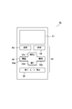
- FIG. 11 shows a front view of the remote controller 50.
- the remote controller 50 includes a display unit 51 and an operation unit 52.
- the display unit 51 is formed of a liquid crystal panel or the like, and displays the light amount of the illumination device 200 and the like.
- the operation unit 52 includes a plurality of operation keys, and includes a turn-on key 53, a turn-off key 54, a cross key 55, a first illumination mode key 56, and a second illumination mode key 57.
- the LED element 6 When the lighting key 53 is operated, the LED element 6 is energized and the lighting device 200 is turned on. By operating the turn-off key 54, the LED element 6 is turned off and the lighting device 200 is turned off.
- the cross key 55 has a cold color portion 55a, a warm color portion 55b, a light increasing portion 55c, and a light reducing portion 55d.
- the illumination color is changed stepwise between the illumination color in the cold color illumination mode and the illumination color in the warm color illumination mode.
- the illumination color can be easily changed by increasing or decreasing the light amount ratio of the white LED element 6a and the light bulb color LED element 6b.
- the brightening portion 55c is marked “bright” on the cross key 55 and increases the amount of illumination light.
- the light reduction unit 55d is marked “dark” on the cross key 55, and reduces the amount of illumination light.
- the first illumination mode key 56 (first operation switch) performs illumination in the first illumination mode.
- the first illumination mode is an orange-pink illumination color
- “color 1” is written on the first illumination mode key 56.
- Other names may be written on the first illumination mode key 56 according to circumstances, such as when the first illumination mode is an illumination color other than orange-pink.
- the second illumination mode key 57 (second operation switch) performs illumination in the second illumination mode.
- the second illumination mode is a light pink illumination color
- “color 2” is written on the second illumination mode key 57.
- Other names may be written on the second illumination mode key 57 according to circumstances, such as when the second illumination mode is an illumination color other than light pink.
- a desired lighting mode is selected by the remote controller 50.
- the CPU 11 instructs the PWM control circuit 13 so that the white LED element 6a, the light bulb color LED element 6b, and the red LED element 6c emit light with a predetermined intensity.
- the PWM control circuit 13 outputs PWM pulses M1, M2, and M3 according to instructions from the CPU 11, and performs color adjustment so that the illumination color corresponds to each illumination mode.
- the light emission of the LED element 6 causes the color matching temperature line W401 and the equal deviation line V401 passing through the point A4 (0.555, 0.394) on the xy chromaticity diagram, and the point B4 (0.419). , 0.343) and a first illumination mode for emitting illumination light of the illumination color in the first region S401 surrounded by the equal color temperature line W402 and the equal deviation line V402. Further, the color matching temperature line W402 and the equal deviation line V402 passing through the point B4, the equal deviation line V401 passing through the point C4 (0.418, 0.390), and the point D4 (0.397, 0.370) are passed.
- a second illumination mode for emitting illumination light of the illumination color in the second region S402 surrounded by the color matching temperature line W403 and a straight line connecting the point C4 and the point D4 is provided. Note that the operation of increasing or decreasing the amount of illumination light in the first illumination mode and the second illumination mode can be performed by the light increasing portion 55c and the light reducing portion 55d of the cross key 55.
- fluorescent lamps may leak ultraviolet rays, and incandescent bulbs are said to emit a lot of infrared rays.
- Ultraviolet rays may have a chemical adverse effect on living organisms and indoor facilities, and infrared rays may have a thermal adverse effect.
- the illumination is performed by the light emission of the LED element 6 that hardly contains ultraviolet rays or infrared rays, the illumination device 200 with less adverse effects on the human body can be provided.
- the operation unit 52 also selects a first illumination mode key 56 (first operation switch) for selecting the first illumination mode, a second illumination mode key 57 (second operation switch) for selecting the second illumination mode, and cold-color illumination.
- a cross key 55 (variable switch) for changing the illumination color stepwise to a color between the mode and the warm color illumination mode.
- the illumination colors that can be expected to have the greatest effect in each of the first area S401 and the second area S402 are set as initial values in the first illumination mode key 56 and the second illumination mode key 57, respectively (initial values in the memory 12). As registered in advance). Accordingly, the user can easily and quickly select a suitable illumination color in the first illumination mode or the second illumination mode.
- first illumination mode key 56 and the second illumination mode key 57 brightness (light quantity of illumination light) suitable for each illumination color is set as an initial value (registered in advance as an initial value of the memory 12). good. Accordingly, the user can easily and quickly select the brightness when using the first illumination mode or the second illumination mode. Therefore, the convenience of the user can be further improved, and the effect of the illumination color can be obtained more suitably.
- the key operation can be performed easily and quickly in this manner, it is possible to avoid as much as possible the troubles and stress caused by the key operation itself. Therefore, the effect on sleep expected by the first illumination mode and the effect on work expected by the second illumination mode are not hindered.
- the white LED element 6a, the light bulb color LED element 6b, and the red LED element 6c that are colored in different colors are included, the illumination light of each illumination color in the first illumination mode, the second illumination mode, the cold color illumination mode, and the warm color illumination mode is provided. Can be easily emitted.
- FIG. 12 is a front view showing a remote controller 50 of the lighting apparatus of the eighth embodiment. Since the basic configuration of this embodiment is the same as that of the seventh embodiment described above with reference to FIGS. 10 and 11, the same reference numerals are assigned to the same components as those of the seventh embodiment. The description of the drawings and the description thereof will be omitted.
- the illumination device 200 of the present embodiment has variable illumination colors in the first region S401 and the second region S402 that are continuous on the xy chromaticity diagram. Other parts are the same as in the fourth embodiment.
- the remote controller 50 is provided with a variable key 58 (first variable switch) for changing the illumination color to the color in the first area S401 and the second area S402.
- a variable key 58 first variable switch
- the illumination color of the first area S401 is changed stepwise from the illumination color of the second area S402 to perform the first illumination mode and the second illumination mode.
- “color 1” and “color 2” written on the variable key 58 may be other names.
- the illumination color is changed stepwise between the illumination color in the cold color illumination mode and the illumination color in the warm color illumination mode.
- variable key 58 for changing the illumination color
- the first illumination mode can be easily set according to the user's state and preference.
- the illumination color in the second illumination mode can be varied.
- variable range of the illumination color by the variable key 58 is limited to the range of the first region S401 and the second region S402. Accordingly, it is possible to prevent the selection of an illumination color that is out of the illumination color range included in the first region S401 or the second region S402 due to the variable operation. For this reason, the effect on the sleep expected by the first illumination mode and the effect on the work expected by the second illumination mode can be obtained. If the first region S401 and the second region S402 are not continuous as in the present embodiment, the illumination is stepped over between the first region S401 and the second region S402. Even if the color is changed, the same effect can be obtained.
- FIG. 13 is a front view showing a remote controller 50 of the lighting apparatus of the ninth embodiment. Since the basic configuration of this embodiment is the same as that of the seventh embodiment described above with reference to FIGS. 10 and 11, the same reference numerals are assigned to the same components as those of the seventh embodiment. The description of the drawings and the description thereof will be omitted.
- Lighting device 200 of this embodiment includes only cold illumination mode and warm illumination mode is omitted, the first illumination mode and a second illumination mode in the fourth embodiment. Other parts are the same as in the fourth embodiment.
- the cross key 55 (see FIG. 11) is omitted from the remote controller 50, and a turn-on key 53, a turn-off key 54, a first illumination mode key 56, and a second illumination mode key 57 are provided.
- the illumination in the first illumination mode is performed by operating the first illumination mode key 56 (first operation switch).
- Illumination in the second illumination mode is performed by operating the second illumination mode key 57 (second operation switch).
- “color 1” written on the first illumination mode key 56 and “color 2” written on the second illumination mode key 57 may be given other names.
- the user can easily select the illumination color of the first illumination mode or the illumination color of the second illumination mode.
- the illumination colors that can be expected to have the greatest effect in each of the first area S401 and the second area S402 are set as initial values in the first illumination mode key 56 and the second illumination mode key 57, respectively (initial values in the memory 12). As registered in advance). Accordingly, the user can easily and quickly select a suitable illumination color in the first illumination mode or the second illumination mode.
- first illumination mode key 56 and the second illumination mode key 57 brightness (light quantity of illumination light) suitable for each illumination color is set as an initial value (registered in advance as an initial value of the memory 12). good. Accordingly, the user can easily and quickly select the brightness when using the first illumination mode or the second illumination mode. Therefore, the convenience of the user can be further improved, and the effect of the illumination color can be obtained more suitably.
- the key operation can be performed easily and quickly in this manner, it is possible to avoid as much as possible the troubles and stress caused by the key operation itself. Therefore, the effect on sleep expected by the first illumination mode and the effect on work expected by the second illumination mode are not hindered.
- the illumination color is made variable in the first area S401 and the second area S402 that are continuous on the xy chromaticity diagram, and the illumination color is changed to the color in the first area S401 and the second area S402.
- a variable key 58 may be provided.
- a variable key for variably increasing / decreasing the amount of illumination light may be provided.
- the amount of illumination light is changed stepwise (for example, light amount 1 ⁇ light amount 2 ⁇ light amount 3 ⁇ light amount 1). You may do it.
- the amount of illumination light may be variably changed according to the time the key is pressed. In this case, it is possible to provide the user with a function of increasing / decreasing the amount of illumination light without providing a new key.
- the illumination colors of the first illumination mode and the second illumination mode may be adjusted by the LED elements 6 of other emission colors.
- a plurality of LED elements that respectively emit blue, green, and red light may be provided.
- a phosphor that converts the emitted light of the LED element and the LED element into different wavelengths may be provided.
- a plurality of LED elements that emit blue light and phosphors that convert blue light into a light bulb color, red, and yellow may be provided corresponding to each LED element.
- White light is formed by the blue light and the yellow light, and the illumination colors in the first illumination mode and the second illumination mode can be adjusted by white, light bulb color, and red light in the same manner as described above.
- the lighting device attached to the room by the lighting device 200 is configured, the lighting device may be a light bulb or the like attached to the lighting device.
- Table 1 shows the specifications of the illumination light of each example and each comparative example.
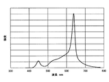
- FIG. 14 shows the spectrum of the illumination light of the illumination device 100 of the first embodiment.
- the vertical axis represents relative intensity
- the horizontal axis represents wavelength (unit: nm).
- the spectrum of the illumination light has an area ratio of 400 nm to 500 nm of 3%, an area ratio of 400 nm to 500 nm of 18%, an area ratio of 500 nm to 600 nm of 18%, and an area ratio of 600 nm to 700 nm of 42%.
- the ratio of the area from 700 nm to 800 nm is 37%.
- the maximum value of the spectrum is included in the wavelength range of 600 nm to 700 nm.
- the value of the spectrum having a wavelength of 550 nm is 38% of the maximum value of the spectrum in the range of 600 nm to 700 nm.
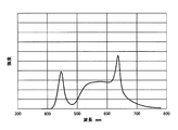
- FIG. 15 shows the spectrum of the illumination light of the illumination device 100 of the second embodiment.
- the vertical axis represents relative intensity
- the horizontal axis represents wavelength (unit: nm).
- the spectrum of the illumination light has an area ratio of 400 nm to 500 nm of 7%, an area ratio of 500 nm to 600 nm of 29%, an area ratio of 600 nm to 700 nm of 57%, with respect to an area having a wavelength of 400 nm to 800 nm.
- the ratio of the area from 700 nm to 800 nm is 7%.
- the maximum value of the spectrum is included in the wavelength range of 600 nm to 700 nm.
- the value of the spectrum having a wavelength of 550 nm is 16% of the maximum value of the spectrum in the range of 600 nm to 700 nm.
- FIG. 16 shows the spectrum of the illumination light of the illumination device 100 of the third embodiment.
- the vertical axis represents relative intensity
- the horizontal axis represents wavelength (unit: nm).
- the spectrum of the illumination light has an area ratio from 400 nm to 500 nm of 18%, an area ratio from 400 nm to 500 nm is 18%, an area ratio from 500 nm to 600 nm is 41%, an area ratio from 600 nm to 700 nm is 35%, The ratio of the area from 700 nm to 800 nm is 6%.
- the maximum value of the spectrum is included in the wavelength range of 600 nm to 700 nm.
- the value of the spectrum having a wavelength of 550 nm is 38% of the maximum value of the spectrum in the range of 600 nm to 700 nm.
- FIG. 17 shows the spectrum of the illumination light of the illumination device 100 of the fourth embodiment.
- the vertical axis represents relative intensity
- the horizontal axis represents wavelength (unit: nm).
- the illumination light spectrum has an area ratio of 400 nm to 500 nm of 9%, an area ratio of 500 nm to 600 nm of 36%, an area ratio of 600 nm to 700 nm of 50% with respect to an area of wavelength 400 nm to 800 nm, The ratio of the area from 700 nm to 800 nm is 5%.
- the maximum value of the spectrum is included in the wavelength range of 600 nm to 700 nm.
- the value of the spectrum having a wavelength of 550 nm is 31% of the maximum value of the spectrum in the range of 600 nm to 700 nm.
- the spectrum of the illumination light of the illumination device 100 of Comparative Example 1 compared with Examples 1 to 4 is 18% of the area ratio of 400 nm to 500 nm with respect to the area of wavelength 400 nm to 800 nm, and the area of 500 nm to 600 nm. Ratio is 40%, the area ratio from 600 nm to 700 nm is 25%, and the area ratio from 700 nm to 800 nm is 17%.
- the maximum value of the spectrum is included in the wavelength range of 600 nm to 700 nm.
- the value of the spectrum having a wavelength of 550 nm is 68% of the maximum value of the spectrum in the range of 600 nm to 700 nm.
- the spectrum of the illumination light of the illumination device 100 of Comparative Example 2 is that the wavelength ratio is 400% to 800 nm, the area ratio of 400 nm to 500 nm is 4%, the area ratio of 500 nm to 600 nm is 18%, and 600 nm to 700 nm. The area ratio is 75%, and the area ratio from 700 nm to 800 nm is 3%.
- the maximum value of the spectrum is included in the wavelength range of 600 nm to 700 nm.
- the value of the spectrum having a wavelength of 550 nm is 15% of the maximum value of the spectrum in the range of 600 nm to 700 nm.
- the spectrum of the illumination light of the illumination device 100 of the comparative example 3 is that the area ratio from 400 nm to 500 nm is 3%, the area ratio from 500 nm to 600 nm is 13%, and the area ratio from 500 nm to 600 nm is 13%, from 600 nm to 700 nm.
- the area ratio is 50%, and the area ratio from 700 nm to 800 nm is 34%.
- the maximum value of the spectrum is included in the wavelength range of 600 nm to 700 nm. Further, the value of the spectrum having a wavelength of 550 nm is 10% of the maximum value of the spectrum in the range of 600 nm to 700 nm.
- the spectrum of the illumination light of the illumination device 100 of Comparative Example 4 is that the area ratio from 400 nm to 500 nm is 4%, the area ratio from 500 nm to 600 nm is 47%, and the area ratio from 500 nm to 600 nm is 47% to 600 nm to 700 nm. The area ratio is 48%, and the area ratio from 700 nm to 800 nm is 1%.
- the maximum value of the spectrum is included in the wavelength range of 600 nm to 700 nm.
- the value of the spectrum having a wavelength of 550 nm is 63% of the maximum value of the spectrum in the range of 600 nm to 700 nm.
- the spectrum of the illumination light of the illumination device 100 of Comparative Example 5 is that the ratio of the area from 400 nm to 500 nm is 22%, the ratio of the area from 500 nm to 600 nm is 20%, and the area ratio from 500 nm to 600 nm is 20% to 600 nm to 700 nm.
- the area ratio is 56%, and the area ratio from 700 nm to 800 nm is 2%.
- the maximum value of the spectrum is included in the wavelength range of 600 nm to 700 nm.
- the value of the spectrum having a wavelength of 550 nm is 55% of the maximum value of the spectrum in the range of 600 nm to 700 nm.
- the spectrum of the illumination light of the illumination device 100 of Comparative Example 6 is that the area ratio from 400 nm to 500 nm is 18%, the area ratio from 500 nm to 600 nm is 12%, and the area ratio from 400 nm to 800 nm is 600% to 700 nm. The area ratio is 31%, and the area ratio from 700 nm to 800 nm is 39%.
- the maximum value of the spectrum is included in the wavelength range of 700 nm to 800 nm. Further, the value of the spectrum having a wavelength of 550 nm is 28% of the maximum value of the spectrum in the range of 600 nm to 700 nm.
- the spectrum of the illumination light of the illumination device 100 of Comparative Example 7 is that the ratio of the area of 400 nm to 500 nm is 11%, the ratio of the area of 500 nm to 600 nm is 43%, and the area ratio of 600 nm to 700 nm is 400 nm to 800 nm. The area ratio is 41%, and the area ratio from 700 nm to 800 nm is 5%.
- the maximum value of the spectrum is included in the wavelength range of 600 nm to 700 nm.
- the value of the spectrum having a wavelength of 550 nm is 65% of the maximum value of the spectrum in the range of 600 nm to 700 nm.
- the illumination light of the illuminating device 100 of Comparative Example 8 has a light bulb color, and the spectrum of the illumination light is 13% of the area ratio of 400 nm to 500 nm and the area ratio of 500 nm to 600 nm with respect to the area of wavelength 400 nm to 800 nm. 42%, the ratio of the area from 600 nm to 700 nm is 41%, and the ratio of the area from 700 nm to 800 nm is 4%.
- the maximum value of the spectrum is included in the wavelength range of 600 nm to 700 nm.
- the value of the spectrum having a wavelength of 550 nm is 63% of the maximum value of the spectrum in the range of 600 nm to 700 nm.
- “lunch white” and “bulb color” correspond to the light source colors defined by the JIS standard (JIS Z 8110).
- the daylight white spectrum has an area ratio of 400 nm to 800 nm, an area ratio of 400 nm to 500 nm is 24%, an area ratio of 500 nm to 600 nm is 47%, and an area ratio of 600 nm to 700 nm is 24%, 700 nm.
- the ratio of the area of 800 nm to 5% is 5%.
- the maximum value of the daylight white spectrum is included in the wavelength range of 400 nm to 500 nm.
- the value of the spectrum having a wavelength of 550 nm is 125% of the maximum value of the spectrum in the range of 600 nm to 700 nm.
- a total of 32 subjects were selected from 16 healthy men and 16 males and 16 females.
- subjects were kept waiting for each room during the day, and all subjects were in the same environmental condition, and each illumination light was irradiated for 30 minutes during the working time.
- the arrangement and the number of the illumination devices 100 were adjusted so that the illuminance of the illumination light was equivalent to a ceiling light of 100 W (about 600 lx) on the desk where the work was performed. And it compared with the evaluation at the time of irradiating lunch white by equivalent to 100W similarly.
- ⁇ Kraepelin test was used for workload.
- the content of the test is a calculation work load for a total of 30 minutes while changing a line every minute for a simple single digit addition.
- the Kraepelin test in this experiment was conducted using a personal computer (hereinafter referred to as “personal computer”).
- the subject entered the answer by operating the keys on the computer for the problem displayed on the computer screen. Answer contents during work and answer input time are sequentially stored as data in a personal computer, and the data is analyzed after the test, and the number of trials, correct answer rate, average reaction time (after the problem is displayed, the answer is input) Each time) was obtained as a result of the test.
- Table 2 shows the evaluation items of the first experiment. As evaluation items, subjective evaluation during work (evaluation items 1 to 8), autonomic nervous system evaluation (evaluation item 9), and work efficiency (evaluation items 10 to 12) were provided.
- VAS Visual Analogue Scale
- the question items are “comfort (evaluation item 1)”, “motivation (evaluation item 2)”, “fatigue (evaluation item 3)”, “drowsiness (evaluation item 4)", "feeling of fulfillment (evaluation item 5)” ”,“ Relaxation (Evaluation Item 6) ”,“ Irritation (Evaluation Item 7) ”, and“ Warmness (Evaluation Item 8) ”.
- an acceleration pulse wave measurement system “Altet C (registered trademark)” manufactured by Yumedica Co., Ltd. was used.
- the acceleration pulse wave measurement system measures acceleration pulse waves during and before and after the work, and performs frequency analysis of the time change data. Thereby, LF, HF, and LF / HF, which are indices of autonomic nervous function, were calculated, and the state of the autonomic nervous system was evaluated.
- the work efficiency was evaluated based on the number of trials (evaluation item 10), the correct answer rate (evaluation item 11), and the average reaction time (evaluation item 12) based on the workload for 30 minutes.
- Table 3 shows the results of the first experiments of Examples 1 to 4 and Comparative Examples 1 to 8.
- the results of all the subjects were statistically analyzed, and a significant difference test between each illumination light and daylight white was performed.
- a t-test was used as the test method, and the case where there was a significant difference in improvement with a significance level of 5% was indicated by “ ⁇ ”.
- a significance probability of less than 10% was evaluated as having an improvement tendency and indicated by “ ⁇ ”.
- the case where there is no significant difference or trend of improvement is indicated by “x”.
- the illumination light of Examples 1 to 4 has a useful result in subjective evaluation and autonomic nervous system evaluation during work as compared with daylight white. That is, it is possible to improve the user's comfort and relaxation during work.
- Example 1 the number of trials tended to improve in Example 1, Example 3, and Example 4.
- the correct answer rate was improved or improved in Examples 1 to 4.
- the average reaction time was improved or improved in Examples 1 to 4.
- Comparative Example 1 has a spectrum in which the ratio of the area of 600 nm to 700 nm is smaller than 30% with respect to the area of the wavelength of 400 nm to 800 nm. I could't see it. Comparative Example 2 has a spectrum in which the ratio of the area of 600 nm to 700 nm is greater than 70% with respect to the area of the wavelength of 400 nm to 800 nm, and no significant difference or trend was observed compared to daylight white.
- Comparative Example 3 has a spectrum in which the ratio of the area of 500 nm to 600 nm is smaller than 15% with respect to the area of the wavelength of 400 nm to 800 nm, and no significant difference or tendency was observed compared with daylight white.
- Comparative Example 4 had a spectrum in which the ratio of the area from 500 nm to 600 nm was greater than 45% with respect to the area having a wavelength of 400 nm to 800 nm, and no significant difference or trend was observed compared to daylight white.
- Comparative Example 5 has a spectrum in which the ratio of the area of 400 nm to 500 nm is greater than 10% with respect to the area of the wavelength of 400 nm to 800 nm, and no significant difference or trend was observed compared to daylight white.
- Comparative Example 6 the maximum value of the spectrum was included in the range of 700 nm to 800 nm, and no significant difference or tendency was observed compared with daylight white.
- Comparative Examples 7 and 8 the ratio of the value of the spectrum at 550 nm to the maximum value of the spectrum in the range of 600 nm to 700 nm is greater than 50%. In Comparative Example 7, no significant difference or trend was observed compared with daytime white. Moreover, although the comparative example 8 of the lightbulb color showed the significant difference about the subjectivity (warmth feeling) compared with lunch white, the significant difference and the tendency were not seen about the other evaluation items.
- Table 4 shows the specifications of the illumination light of each example and each comparative example.
- FIG. 18 shows the spectrum of the illumination light of the illumination device 200 of the fifth embodiment.
- the vertical axis represents intensity
- the horizontal axis represents wavelength (unit: nm).
- the spectrum of the illumination light has an area ratio of 400 nm to 500 nm of 3%, an area ratio of 400 nm to 500 nm of 18%, an area ratio of 500 nm to 600 nm of 18%, and an area ratio of 600 nm to 700 nm of 42%.
- the ratio of the area from 700 nm to 800 nm is 37%.
- the maximum value of the spectrum is included in the wavelength range of 600 nm to 700 nm. Further, the maximum value of the spectrum in the wavelength range of 500 nm to 600 nm is 50% of the maximum value of the spectrum in the range of 600 nm to 700 nm.
- FIG. 19 shows the spectrum of the illumination light of the illumination device 200 of the sixth embodiment.
- the vertical axis represents intensity
- the horizontal axis represents wavelength (unit: nm).
- the spectrum of the illumination light has an area ratio of 400 nm to 500 nm of 7%, an area ratio of 500 nm to 600 nm of 29%, an area ratio of 600 nm to 700 nm of 57%, with respect to an area having a wavelength of 400 nm to 800 nm.
- the ratio of the area from 700 nm to 800 nm is 7%.
- the maximum value of the spectrum is included in the wavelength range of 600 nm to 700 nm.
- the maximum value of the spectrum in the wavelength range of 500 nm to 600 nm is 28% of the maximum value of the spectrum in the range of 600 nm to 700 nm.
- FIG. 20 shows the spectrum of the illumination light of the illumination device 200 of the seventh embodiment.
- the vertical axis represents intensity
- the horizontal axis represents wavelength (unit: nm).
- the spectrum of the illumination light has an area ratio from 400 nm to 500 nm of 18%, an area ratio from 400 nm to 500 nm is 18%, an area ratio from 500 nm to 600 nm is 41%, an area ratio from 600 nm to 700 nm is 35%, The ratio of the area from 700 nm to 800 nm is 6%.
- the maximum value of the spectrum is included in the wavelength range of 600 nm to 700 nm.
- the maximum value of the spectrum in the wavelength range of 500 nm to 600 nm is 42% of the maximum value of the spectrum in the range of 600 nm to 700 nm.
- FIG. 21 shows the spectrum of the illumination light of the illumination device 200 of the eighth embodiment.
- the vertical axis represents intensity
- the horizontal axis represents wavelength (unit: nm).
- the spectrum of the illumination light has an area ratio of 400 nm to 500 nm of 19%, an area ratio of 500 nm to 600 nm of 44%, an area ratio of 600 nm to 700 nm of 31% with respect to an area of wavelength 400 nm to 800 nm, The ratio of the area from 700 nm to 800 nm is 6%.
- the maximum value of the spectrum is included in the wavelength range of 600 nm to 700 nm. Further, the maximum value of the spectrum in the wavelength range of 500 nm to 600 nm is 66% of the maximum value of the spectrum in the range of 600 nm to 700 nm.
- the spectrum of the illumination light of the illumination device 200 of Comparative Example 9 compared with Examples 5 to 8 is 18% in the area ratio of 400 nm to 500 nm with respect to the area of wavelength 400 nm to 800 nm, and the area of 500 nm to 600 nm. Ratio is 40%, the area ratio from 600 nm to 700 nm is 25%, and the area ratio from 700 nm to 800 nm is 17%.
- the maximum value of the spectrum is included in the wavelength range of 600 nm to 700 nm.
- the maximum value of the spectrum in the wavelength range of 500 nm to 600 nm is 68% of the maximum value of the spectrum in the range of 600 nm to 700 nm.
- the spectrum of the illumination light of the illumination device 200 of Comparative Example 10 is that the ratio of the area from 400 nm to 500 nm is 4%, the ratio of the area from 500 nm to 600 nm is 18%, and the area from 600 nm to 700 nm is 400 nm to 800 nm.
- the area ratio is 75%, and the area ratio from 700 nm to 800 nm is 3%.
- the maximum value of the spectrum is included in the wavelength range of 600 nm to 700 nm. Further, the maximum value of the spectrum in the wavelength range of 500 nm to 600 nm is 24% of the maximum value of the spectrum in the range of 600 nm to 700 nm.
- the spectrum of the illumination light of the illumination device 200 of Comparative Example 11 is that the area ratio from 400 nm to 500 nm is 3%, the area ratio from 500 nm to 600 nm is 13%, and the area ratio from 500 nm to 600 nm is 13%, from 600 nm to 700 nm.
- the area ratio is 50%, and the area ratio from 700 nm to 800 nm is 34%.
- the maximum value of the spectrum is included in the wavelength range of 600 nm to 700 nm.
- the maximum value of the spectrum in the wavelength range of 500 nm to 600 nm is 16% of the maximum value of the spectrum in the range of 600 nm to 700 nm.
- the spectrum of the illumination light of the illumination device 200 of Comparative Example 12 is that the wavelength ratio is 400% to 800 nm, the area ratio of 400 nm to 500 nm is 4%, the area ratio of 500 nm to 600 nm is 47%, and 600 nm to 700 nm. The area ratio is 48%, and the area ratio from 700 nm to 800 nm is 1%.
- the maximum value of the spectrum is included in the wavelength range of 600 nm to 700 nm. Further, the maximum value of the spectrum in the wavelength range of 500 nm to 600 nm is 65% of the maximum value of the spectrum in the range of 600 nm to 700 nm.
- the spectrum of the illumination light of the illumination device 200 of Comparative Example 13 is that the area ratio from 400 nm to 500 nm is 22%, the area ratio from 500 nm to 600 nm is 20%, and the area ratio from 500 nm to 600 nm is 20% to 600 nm to 700 nm.
- the area ratio is 56%, and the area ratio from 700 nm to 800 nm is 2%.
- the maximum value of the spectrum is included in the wavelength range of 600 nm to 700 nm.
- the maximum value of the spectrum in the wavelength range of 500 nm to 600 nm is 60% of the maximum value of the spectrum in the range of 600 nm to 700 nm.
- the spectrum of the illumination light of the illumination device 200 of Comparative Example 14 is 18% in the area ratio from 400 nm to 500 nm, 12% in the area ratio from 500 nm to 600 nm, and 600 nm to 700 nm in the area from 400 nm to 500 nm.
- the area ratio is 31%, and the area ratio from 700 nm to 800 nm is 39%.
- the maximum value of the spectrum is included in the wavelength range of 700 nm to 800 nm.
- the maximum value of the spectrum in the wavelength range of 500 nm to 600 nm is 45% of the maximum value of the spectrum in the range of 600 nm to 700 nm.
- the spectrum of the illumination light of the illumination device 200 of Comparative Example 15 is that the area ratio from 400 nm to 500 nm is 17%, the area ratio from 500 nm to 600 nm is 40%, and the area ratio from 500 nm to 600 nm is 40% to 600 nm to 700 nm.
- the area ratio is 34%, and the area ratio from 700 nm to 800 nm is 9%.
- the maximum value of the spectrum is included in the wavelength range of 600 nm to 700 nm. Further, the maximum value of the spectrum in the wavelength range of 500 nm to 600 nm is 75% of the maximum value of the spectrum in the range of 600 nm to 700 nm.
- the illumination light of the illumination device 200 of Comparative Example 16 has a light bulb color, and the spectrum of the illumination light is 13% in the ratio of the area from 400 nm to 500 nm to the area in the wavelength range from 400 nm to 800 nm, and the ratio of the area from 500 nm to 600 nm. 42%, the ratio of the area from 600 nm to 700 nm is 41%, and the ratio of the area from 700 nm to 800 nm is 4%.
- the maximum value of the spectrum is included in the wavelength range of 600 nm to 700 nm. Further, the maximum value of the spectrum in the wavelength range of 500 nm to 600 nm is 98% of the maximum value of the spectrum in the range of 600 nm to 700 nm.
- “lunch white” and “bulb color” correspond to the light source colors defined by the JIS standard (JIS Z 8110).
- the daylight white spectrum has an area ratio of 400 nm to 800 nm, an area ratio of 400 nm to 500 nm is 24%, an area ratio of 500 nm to 600 nm is 47%, and an area ratio of 600 nm to 700 nm is 24%, 700 nm.
- the ratio of the area of 800 nm to 5% is 5%.
- the maximum value of the daylight white spectrum is included in the wavelength range of 400 nm to 500 nm. Further, the maximum value of the spectrum in the wavelength range of 500 nm to 600 nm is 125% of the maximum value of the spectrum in the range of 600 nm to 700 nm.
- a total of 32 subjects were selected from 16 healthy men and 16 males and 16 females.
- subjects were kept waiting for each room from the evening to the morning of the next day, and all the subjects were in the same environmental condition, and were irradiated with each of the above illumination lights from 1 hour before bedtime to bedtime.
- the illuminance of the illumination light was equivalent to 35 W (about 45 lx) at the pillow position.
- the daylight white color correlated color temperature 5000K
- the work load used was “Uchida-Kraepelin Test (registered trademark)” of the Japan Institute of Philosoph Technology.
- the content of the inspection is a calculation workload for performing a simple one-digit addition every 30 minutes while changing the line every minute.
- Table 5 shows the evaluation items based on the second and third experiments.
- subjective evaluation before going to bed and during sleep, and evaluation by measurement of sleep status were performed (evaluation items 1 to 22).
- evaluation items 23 to 25 the autonomic nervous system, work efficiency, and fatigue were evaluated.
- VAS Visual Analogue Scale
- the question items are “comfort (evaluation item 1)”, “motivation (evaluation item 2)”, “fatigue (evaluation item 3)”, “drowsiness (evaluation item 4)", "feeling of fulfillment (evaluation item 5)” ”,“ Relaxation (Evaluation Item 6) ”,“ Irritation (Evaluation Item 7) ”, and“ Warmness (Evaluation Item 8) ”.
- the subjective evaluation during sleep used a self-administered questionnaire that evaluates the 24-hour sleep immediately before called the St. Mary's Hospital Sleep Questionnaire.
- the question items are "subjective sleep depth (evaluation item 9)", “number of times I woke up (evaluation item 10)", “I slept well (evaluation item 11)", "whether the head was clean (Evaluation Item 12), “Sleep Satisfaction (Evaluation Item 13)”, “Whether Awakened in the Early Morning (Evaluation Item 14)”, and “Sleeping Situation (Evaluation Item 15)”.
- a sleep measurement system was placed under the bed to measure the amount of activity of each subject sleeping. Based on the acquired activity amount, the average activity amount (evaluation item 16), sleep latency (evaluation item 17), sleep efficiency (evaluation item 18), number of awakenings (evaluation item 19), number of getting out of bed (evaluation item 20) ), Total sleep time (evaluation item 21), midway awakening time (evaluation item 22).
- an acceleration pulse wave measurement system “Altet C (registered trademark)” manufactured by Yumedica Co., Ltd. was used.
- the acceleration pulse wave measurement system measures acceleration pulse waves during and before and after the work, and performs frequency analysis of the time change data. Thereby, LF, HF, and LF / HF, which are indices of autonomic nervous function, were calculated, and the state of the autonomic nervous system was evaluated.
- Work efficiency was calculated by calculating the work load for the above 30 minutes.
- the degree of fatigue was evaluated by conducting a blood test for measuring TGF-beta in blood sampled by blood sampling.
- Table 6 shows the results of the second and third experiments of Examples 5 to 8 and Comparative Examples 9 to 16.
- the results of all the subjects were statistically analyzed, and a significant difference test between each illumination light and daylight white was performed.
- a t-test was used as the test method, and the case where there was a significant difference in improvement with a significance level of 5% was indicated by “ ⁇ ”.
- a significance probability of less than 10% was evaluated as having an improvement tendency and indicated by “ ⁇ ”.
- the case where there is no significant difference or trend of improvement is indicated by “x”.
- the illumination light of Examples 5 to 8 has a useful result in subjective evaluation before going to bed and evaluation during work, compared with daylight white. That is, it is possible to give a user a feeling of comfort and relaxation during a break and to reduce fatigue during work.
- Example 5 and 6 the item regarding sleep is improving or improving, and sleep efficiency etc. can be improved. Furthermore, the working efficiency of Example 5, Example 7, and Example 8 is improving or improving.
- Comparative Example 9 has a spectrum in which the ratio of the area of 600 nm to 700 nm is smaller than 30% with respect to the area of the wavelength of 400 nm to 800 nm. I could't see it. Comparative Example 10 had a spectrum in which the ratio of the area of 600 nm to 700 nm was larger than 70% with respect to the area of the wavelength of 400 nm to 800 nm, and no significant difference or trend was observed compared with daylight white.
- Comparative Example 11 has a spectrum in which the ratio of the area of 500 nm to 600 nm is smaller than 15% with respect to the area of the wavelength of 400 nm to 800 nm, and no significant difference or tendency was seen compared with daylight white.
- Comparative Example 12 had a spectrum in which the ratio of the area from 500 nm to 600 nm was larger than 45% with respect to the area having a wavelength of 400 nm to 800 nm, and no significant difference or tendency was found compared to daylight white.
- Comparative Example 13 had a spectrum in which the ratio of the area from 400 nm to 500 nm was greater than 10% with respect to the area of the wavelength from 400 nm to 800 nm, and no significant difference or trend was seen compared to daylight white.
- Comparative Example 14 the maximum value of the spectrum was included in the range of 700 nm to 800 nm, and no significant difference or tendency was observed compared with daylight white.
- Comparative Example 15 and Comparative Example 16 the ratio of the maximum value of the spectrum in the range of 500 nm to 600 nm to the maximum value of the spectrum in the range of 600 nm to 700 nm is greater than 70%. In Comparative Example 15, no significant difference or tendency was found compared with daytime white. Moreover, although the light bulb color comparative example 16 showed a significant difference in subjectivity (warmth) as compared with lunch white, no significant difference or tendency was observed in other evaluation items.
- FIG. 22 shows an enlarged view of the xy chromaticity diagram of FIG.
- the points of the following Examples 9, 10,... Are indicated by p101, p102,..., And the points of Comparative Examples 17, 18,.
- the illuminating device 200 of Example 9 emits the illumination light of the illumination color of point A1 (0.555, 0.394) (point p101 of FIG. 22) of area
- the illumination device 200 emits illumination light having the illumination color of the point (0.537, 0.373) (the point p102 in FIG. 22) on the color matching temperature line W101 in the region S101.
- the illuminating device 200 of Example 11 emits the illumination light of the illumination color of the point C1 (0.510, 0.340) (point p103 in FIG. 22) of the region S101.
- the illuminating device 200 of Example 12 emits illumination light of the illumination color of the point (0.515, 0.404) (point p104 in FIG. 22) on the equal deviation line V101 in the region S101.
- the illumination device 200 of Example 13 emits illumination light of the illumination color at the point E1 (0.499, 0.382) (point p105 in FIG. 22) inside the region S101.
- the illumination device 200 emits illumination light having the illumination color of the point (0.473, 0.347) (the point p106 in FIG. 22) on the equal deviation line V102 in the region S101.
- the illuminating device 200 of Example 15 emits illumination light of the illumination color at the point D1 (0.453, 0.401) (point p107 in FIG. 22) in the region S101.
- the illuminating device 200 of Example 16 emits illumination light of the illumination color of the point (0.440, 0.378) (point p108 in FIG. 22) on the color matching temperature line W102 in the region S101.
- the illuminating device 200 of Example 17 emits the illumination light of the illumination color of the point B1 (0.419, 0.343) (point p109 in FIG. 22) in the region S101.
- Comparative Example 17 the illumination device 200 of Comparative Example 17 compared with Examples 9 to 17 is closer to the black body radiation locus V0 than the equal deviation line V101, and has a lower correlated color temperature than the color matching temperature line W101 (0.586, 0.393) The illumination light of the illumination color (point q101 in FIG. 22) is emitted.
- Comparative Example 18 The illumination device 200 of Comparative Example 18 emits illumination light of the illumination color at the point (0.579, 0.384) (point q102 in FIG. 22) on the equal deviation line V101 having a correlated color temperature lower than that of the uniform color temperature line W101. Exit.
- the illumination device 200 of the comparative example 19 emits illumination light of the illumination color of the point (0.558, 0.364) (point q103 in FIG. 22) whose correlated color temperature is lower than the point of the example 2.
- the illumination device 200 of Comparative Example 20 emits illumination light of the illumination color at the point (0.528, 0.332) (point q104 in FIG. 22) on the equal deviation line V102 having a correlated color temperature lower than that of the uniform color temperature line W101. Exit.
- Comparative Example 21 The illumination device 200 of Comparative Example 21 is farther from the black body radiation locus V0 than the equal deviation line V102, and has a correlated color temperature lower than the uniform color temperature line W101 (0.516, 0.318) (point q105 in FIG. 22). The illumination light of the illumination color is emitted.
- the illumination device 200 of the comparative example 22 illuminates the illumination color at the point (0.563, 0.404) (point q106 in FIG. 22) on the color matching temperature line W101 closer to the blackbody radiation locus V0 than the equal deviation line V101. Emits light.
- the illumination device 200 of the comparative example 23 has the illumination color of the point (0.498, 0.326) (point q107 in FIG. 22) on the color matching temperature line W101 farther from the black body radiation locus V0 than the equal deviation line V102. Illumination light is emitted.
- the illumination device 200 of the comparative example 24 emits illumination light of the illumination color of the point (0.552, 0.414) (point q108 in FIG. 22) closer to the blackbody radiation locus V0 than the point of the fourth embodiment.
- the illumination device 200 of the comparative example 25 emits illumination light of the illumination color at the point (0.462, 0.331) (point q109 in FIG. 22) farther from the blackbody radiation locus V0 than the point of the sixth embodiment.
- the illumination device 200 of the comparative example 26 emits illumination light of the illumination color of the point (0.457, 0.410) (point q110 in FIG. 22) closer to the blackbody radiation locus V0 than the point of the seventh embodiment.
- the illumination device 200 of the comparative example 27 emits illumination light of the illumination color at the point (0.410, 0.328) (point q111 in FIG. 22) farther from the black body radiation locus V0 than the point of the ninth example.
- Comparative Example 28 The lighting device 200 of Comparative Example 28 is closer to the blackbody radiation locus V0 than the equal deviation line V101, and has a higher correlated color temperature than the equal color temperature line W102 (0.437, 0.404) (point q112 in FIG. 22). The illumination light of the illumination color is emitted.
- Lighting device 200 of Comparative Example 29 emits illumination light of the illumination color of the point is higher correlated color temperature (0.433,0.394) (point in Fig. 22 Q113) for points of example 7.
- Lighting device 200 of Comparative Example 30 emits illumination light of the illumination color of the point is higher correlated color temperature (0.422,0.373) (point in Fig. 22 Q114) for points of example 8.
- the illumination device 200 of the comparative example 31 emits illumination light having the illumination color of the point (0.406, 0.339) (point q115 in FIG. 22) having a higher correlated color temperature than the point of the ninth example.
- Comparative Example 32 The illumination device 200 of Comparative Example 32 is farther from the black body radiation locus V0 than the equal deviation line V102, and has a correlated color temperature higher than the color matching temperature line W102 (0.398, 0.324) (point q116 in FIG. 22). The illumination light of the illumination color is emitted.
- VAS Visual Analogue Scale
- the sleep state after irradiating each room with the illumination light of each illumination color from 1 hour before bedtime to bedtime at an equivalent of 35 W (about 45 lx), with the subjects waiting for each room to have the same environmental state. was measured.
- a sleep measurement system “Sleep SCAN (registered trademark)” manufactured by Paramount Bed Co., Ltd. was used. A sleep measurement system was placed under the bed to measure the amount of activity of each subject sleeping, and the sleep latency, sleep efficiency, and total sleep time of each subject were calculated from the amount of activity.
- Tables 7 and 8 show the results of the fourth experiment and the fifth experiment of Examples 9 to 17 and Comparative Examples 17 to 32.
- the results of all the subjects were statistically analyzed, and a significant difference test was performed between each lighting color and daytime white. A t-test was used as a test method, and the significance level was 5%, and “improvement” or “deterioration” was evaluated. In addition, the significance probability of less than 10% was evaluated as “increase tendency” or “deterioration tendency” with a difference.
- the Macadam ellipse 5-Step has a relationship that the length of each of the short side and the long side of the ellipse is five times that of the Macadam ellipse 1-Step.
- FIG. A1 which is a graph of the specifications of the SSL product, is shown.
- the illumination color of the region S101 is a color matching range S102 (FIG. 7) represented by a MacAdam ellipse 5-step centered at a point E1 (0.499, 0.382) (point p105 in FIG. 22).
- the color to which the reference belongs may be used.
- the color may belong to a color matching range represented by the MacAdam ellipse 1-step centered on the point E1.
- FIG. 23 shows an enlarged view of the xy chromaticity diagram of FIG.
- the points of the following Examples 18, 19,... Are indicated by p201, p202,..., And the points of Comparative Examples 33, 34,.
- the illuminating device 200 of Example 18 emits illumination light of the illumination color at the point D2 (0.453, 0.401) (point p201 in FIG. 23) in the region S201.
- the illuminating device 200 of Example 19 emits illumination light of the illumination color of the point (0.446, 0.388) (point p202 in FIG. 23) on the color matching temperature line W201 in the region S201.
- the illuminating device 200 of Example 20 emits illumination light of the illumination color at point A2 (0.419, 0.343) (point p203 in FIG. 23) in the region S201.
- the illuminating device 200 of Example 21 emits illumination light of the illumination color at the point B2 (0.418, 0.390) (point p204 in FIG. 23) in the region S201.
- the illuminating device 200 of Example 22 emits illumination light of the illumination color of the point F2 (0.416, 0.377) (point p205 in FIG. 23) inside the region S201.
- the illumination device 200 of Example 23 emits illumination light of the illumination color of the point (0.397, 0.336) (the point p206 in FIG. 23) on the equal deviation line V201 in the region S201.
- the illuminating device 200 of Example 24 emits the illumination light of the illumination color of the point C2 (0.397, 0.370) (point p207 in FIG. 23) of the region S201.
- the illumination device 200 of Example 25 emits illumination light of the illumination color at the point E2 (0.383, 0.329) (point p208 in FIG. 23) in the region S201.
- the illumination device 200 of the comparative example 33 compared with the examples 18 to 25 is closer to the black body radiation locus V0 than the equal deviation line V202, and has a lower correlated color temperature than the equal color temperature line W201 (0.477, 0.414) The illumination light of the illumination color (point q201 in FIG. 23) is emitted.
- the illumination device 200 of the comparative example 34 emits illumination light of the illumination color of the points (0.471, 0.404) (point q202 in FIG. 23) whose correlated color temperature is lower than the point D2.
- Lighting device 200 of Comparative Example 35 emits illumination light of the illumination color of the point is lower correlated color temperatures (0.462,0.390) (point in Fig. 23 Q203) for points of example 11.
- Lighting device 200 of Comparative Example 36 emits illumination color illumination light points lower correlated color temperatures (0.436,0.347) (point in Fig. 23 Q204) relative to the point A2.
- the illumination device 200 of the comparative example 37 is farther from the black body radiation locus V0 than the equal deviation line V201, and has a correlated color temperature lower than the equal color temperature line W201 (0.429, 0.336) (point q205 in FIG. 23). The illumination light of the illumination color is emitted.
- the illumination device 200 of the comparative example 38 illuminates the illumination color of the point (0.459, 0.410) (point q206 in FIG. 23) on the color matching temperature line W201 closer to the black body radiation locus V0 than the equal deviation line V202. Emits light.
- the illumination device 200 of the comparative example 39 has the illumination color of the point (0.413, 0.333) (point q207 in FIG. 23) on the color matching temperature line W201 farther from the black body radiation locus V0 than the equal deviation line V201. Illumination light is emitted.
- the illumination device 200 of the comparative example 40 emits illumination light of the illumination color of the point (0.420, 0.398) (point q208 in FIG. 23) closer to the blackbody radiation locus V0 than the point B2.
- the illuminating device 200 of the comparative example 41 emits the illumination light of the illumination color of the point (0.392, 0.325) (point q209 in FIG. 23) farther from the black body radiation locus V0 than the point of the example 15.
- the illumination device 200 of the comparative example 42 illuminates the illumination color at the point (0.405, 0.391) (point q210 in FIG. 23) on the color matching temperature line W202 that is closer to the blackbody radiation locus V0 than the equal deviation line V202. Emits light.
- the illumination device 200 of the comparative example 43 emits illumination light of the illumination color at the intersection (0.402, 0.383) (point q211 in FIG. 23) between the equal deviation line V202 and the equal color temperature line W202.
- the illumination device 200 of the comparative example 44 has the illumination color of the point (0.379, 0.319) (point q212 in FIG. 23) on the color matching temperature line W202 farther from the black body radiation locus V0 than the equal deviation line V201. Illumination light is emitted.
- the illumination device 200 of the comparative example 45 is closer to the black body radiation locus V0 than the equal deviation line V202 and has a higher correlated color temperature than the equal color temperature line W202 (0.395, 0.385) (point q213 in FIG. 23). The illumination light of the illumination color is emitted.
- the illumination device 200 of the comparative example 46 emits illumination light of the illumination color at the point (0.392, 0.378) (point q214 in FIG. 23) on the equal deviation line V202 having a correlated color temperature higher than the color matching temperature line W202. Exit.
- the illumination device 200 of the comparative example 47 emits illumination light of the illumination color of the point (0.389, 0.367) (point q215 in FIG. 23) having a correlated color temperature higher than that of the point C2.
- the illumination device 200 of the comparative example 48 emits illumination light of the illumination color of the point (0.375, 0.325) (point q216 in FIG. 23) on the equal deviation line V201 having a correlated color temperature higher than that of the point E2.
- the illumination device 200 of the comparative example 49 is farther from the black body radiation locus V0 than the equal deviation line V201 and has a correlated color temperature higher than the color matching temperature line W202 (0.372, 0.315) (point q217 in FIG. 23). The illumination light of the illumination color is emitted.
- Tables 9 and 10 show the results of the sixth experiment of Examples 18 to 25 and Comparative Examples 33 to 49.
- the results of all the subjects were statistically analyzed, and a significant difference test was performed between each lighting color and daytime white.
- a t-test was used as a test method, and the significance level was 5%, and “improvement” or “deterioration” was evaluated.
- the significance probability of less than 10% was evaluated as “increase tendency” or “deterioration tendency” with a difference.
- the motivation and work efficiency are equivalent to the day white when the day white is equal to the light energy output from the light source.
- 100 W that is, when the daytime white is equivalent to the illuminance on the desk, the motivation and work efficiency tend to be improved or improved as compared to the daylight.
- Example 22 since the work efficiency is significantly improved, it can be greatly expected to improve the work efficiency. It is generally known that the willingness of motivation decreases as fatigue increases, and the improvement in motivation in this experiment is to suppress the progression of the sympathetic nervous system due to workload. This is thought to be due to the reduced feeling of fatigue at the time.
- the illumination color of the region S201 is changed to the point F2 (0.416, 0.377) in FIG. 8 (point p205 in FIG. 23).
- the color may belong to the color matching range S202 (see FIG. 8) represented by the MacAdam ellipse 5-step as the center.
- the color may belong to a color matching range represented by the MacAdam ellipse 1-step centered on the point F2.
- FIG. 24 shows an enlarged view of the xy chromaticity diagram of FIG.
- the points of the following Examples 26, 27,... are indicated by p301, p302,..., And the points of Comparative Examples 50, 51,.
- the illuminating device 200 of Example 26 emits illumination light of the illumination color at point B3 (0.397, 0.370) (point p301 in FIG. 24) in the region S301.
- the illumination device 200 of Example 27 emits illumination light of the illumination color at the point D3 (0.383, 0.329) (the point p302 in FIG. 24) in the region S301.
- the illumination device 200 of Example 28 emits illumination light of the illumination color at the point C3 (0.388, 0.378) in the region S301 (point p303 in FIG. 24).
- the illuminating device 200 of Example 29 emits the illumination light of the illumination color of the point (0.380, 0.373) (point p304 in FIG. 24) on the equal deviation line V302 in the region S301.
- the illumination device 200 of Example 30 emits illumination light of the illumination color of the point F3 (0.377, 0.362) (point p305 in FIG. 24) inside the region S301.
- the illuminating device 200 of Example 31 emits illumination light of the illumination color of the point (0.365, 0.322) (point p306 in FIG. 24) on the equal deviation line V301 in the region S301.
- the illuminating device 200 of Example 32 emits illumination light of the illumination color at point E3 (0.359, 0.358) (point p307 in FIG. 24) in the region S301.
- the illuminating device 200 of Example 33 emits illumination light of the illumination color of the point (0.357, 0.349) (point p308 in FIG. 24) on the color matching temperature line W301 in the region S301.
- the illuminating device 200 of Example 34 emits illumination light of the illumination color at point A3 (0.350, 0.311) (point p309 in FIG. 24) in the region S301.
- the illumination device 200 of the comparative example 50 compared with the examples 26 to 34 is close to the black body radiation locus V0 with respect to the point of the example 20, and has a low correlated color temperature (0.405, 0.391) ( The illumination light of the illumination color at point q301) in FIG. 24 is emitted.
- Comparative Example 51 The illumination device 200 of Comparative Example 51 has the same deviation from the blackbody radiation locus V0 as compared to the point of Example 20, and the correlated color temperature is low (0.403, 0.385) (points in FIG. 24). The illumination light of the illumination color q302) is emitted.
- the illumination device 200 of the comparative example 52 emits illumination light having the illumination color of the points (0.403, 0.372) (point q303 in FIG. 24) whose correlated color temperature is lower than that of the example 18.
- Lighting device 200 of Comparative Example 53 emits illumination color illumination light points lower correlated color temperatures for points of example 19 (0.394,0.331) (point in Fig. 24 Q304).
- the illumination device 200 of the comparative example 54 is farther from the black body radiation locus V0 than the equal deviation line V301, and has a correlated color temperature lower than the color matching temperature line W302 (0.389, 0.320) (point q305 in FIG. 24). The illumination light of the illumination color is emitted.
- the illumination device 200 of the comparative example 55 emits illumination light of the illumination color of the point (0.390, 0.382) (point q306 in FIG. 24) closer to the blackbody radiation locus V0 than the point of the twentieth example.
- the illumination device 200 of the comparative example 56 emits illumination light of the illumination color at the point (0.378, 0.318) (point q307 in FIG. 24) farther from the black body radiation locus V0 than the point of the example 19.
- the illumination device 200 of the comparative example 57 emits illumination light of the illumination color of the point (0.381, 0.377) (point q308 in FIG. 24) closer to the blackbody radiation locus V0 than the point of the example 21.
- the illumination device 200 of the comparative example 58 emits illumination light of the illumination color of the point (0.362, 0.311) (point q309 in FIG. 24) farther from the blackbody radiation locus V0 than the point of the example 23.
- the illumination device 200 of the comparative example 59 emits illumination light of the illumination color of the point (0.359, 0.363) (point q310 in FIG. 24) closer to the blackbody radiation locus V0 than the point of the example 24.
- the illumination device 200 of the comparative example 60 emits illumination light of the illumination color of the point (0.348, 0.302) (point q311 in FIG. 24) farther from the blackbody radiation locus V0 than the point of the example 26.
- the illumination device 200 of the comparative example 61 is closer to the black body radiation locus V0 than the equal deviation line V302 and has a higher correlated color temperature than the equal color temperature line W301 (0.351, 0.357) (point q312 in FIG. 24). The illumination light of the illumination color is emitted.
- the illumination device 200 of the comparative example 62 emits illumination light of the illumination color of the points (0.351, 0.353) (point q313 in FIG. 24) whose correlated color temperature is higher than that of the example 24.
- Lighting device 200 of Comparative Example 63 emits illumination color illumination light points higher correlated color temperature with respect to a point of Example 25 (0.349,0.345) (point in Fig. 24 q314).
- the illumination device 200 of the comparative example 64 emits illumination light having the illumination color of the points (0.341, 0.305) (point q315 in FIG. 24) having a higher correlated color temperature than the point of the example 26.
- Comparative Example 65 The illumination device 200 of Comparative Example 65 is farther from the black body radiation locus V0 than the equal deviation line V301 and has a higher correlated color temperature than the equal color temperature line W301 (0.340, 0.295) (point q316 in FIG. 24). The illumination light of the illumination color is emitted.
- Example 26 to 34 and Comparative Examples 50 to 65 were performed on Examples 26 to 34 and Comparative Examples 50 to 65.
- the correlation color temperature of daytime white is about 5000K
- the deviation from the blackbody radiation locus V0 is 0, and the chromaticity coordinates are (0.345, 0.342) (point q0 in FIG. 24).
- VAS Visual Analogue Scale
- amylase measurement value was used as an evaluation method. Stress applied to the body promotes excitement of the sympathetic nervous system through the hypothalamus of the sympathetic nervous system. This excitement activates amylase as well as various digestive enzymes that promote toxic decomposition in the digestive tract as a self-defense reaction in the body against external stress. By collecting salivary amylase, it is possible to determine how much stress has been applied.
- a commercially available stress measuring instrument such as salivary amylase monitor CM-2.1 manufactured by Nipro Corporation can be used. When the measured value of amylase is 30 KU / L or less, it can be determined that there is no stress, and when it is 45 KU / L or more, it can be determined that there is a stress.
- amylase experiments (1) and (2) The evaluation based on the amylase measurement value was further divided into two experimental methods. Hereinafter, the amylase experiments (1) and (2) will be described.
- the test method of the amylase experiment (1) is to divide the test subjects into two groups and make a stressful state by first performing a 30-minute Kraepelin test (computation workload) in the same room with the daytime white irradiation. Amylase measurement was performed. Then, amylase measurement was performed when illumination light of any illumination color was irradiated for 30 minutes, and then amylase measurement was performed when the illumination was returned to daylight white illumination again.
- amylase experiment (2) the test subjects were divided into two groups, and the amylase measurement was performed in a stress-free state by first irradiating lunch white in the same room. Then, amylase measurement was performed when illumination light of any illumination color was irradiated for 30 minutes, and then amylase measurement was performed when the illumination was returned to daylight white illumination again.
- Tables 11 and 12 show the results of the seventh experiment and the eighth experiment of Examples 26 to 34 and Comparative Examples 50 to 65.
- the results of all the subjects were statistically analyzed, and a significant difference test was performed between each lighting color and daytime white.
- the t-test was used as the test method, and the evaluation was evaluated as “improvement (reduction)” or “deterioration” with a significance level of 5%.
- the significance probability of less than 10% was evaluated as “increase tendency” or “deterioration tendency” with a difference.
- the illumination color is favored and the stress can be reduced.
- the illumination color of the region S301 is set to point F3 (0.377, 0.362) in FIG. 9 (point p305 in FIG. 24).
- the color may belong to the color matching range S302 (see FIG. 9) represented by the MacAdam ellipse 5-step as the center.
- the color may belong to a color matching range represented by the MacAdam ellipse 1-step centered on the point F3.
- FIG. 25 shows an enlarged view of the xy chromaticity diagram of FIG.
- the points of the following Examples 35, 36,... are indicated by p401, p402,..., And the points of Comparative Examples 66, 67,.
- the illuminating device 200 of Example 35 emits illumination light of the illumination color at point A4 (0.555, 0.394) (point p401 in FIG. 25) in the first region S401.
- the illumination device 200 of Example 36 emits illumination light of the illumination color of the point (0.537, 0.373) (point p402 in FIG. 25) on the color matching temperature line W401 in the first region S401.
- the illumination device 200 of Example 37 emits illumination light of the illumination color at the point E4 (0.510, 0.340) (point p403 in FIG. 25) in the first region S401.
- the illuminating device 200 of Example 38 emits the illumination light of the illumination color of the point (0.515, 0.404) (point p404 in FIG. 25) on the equal deviation line V401 of the first region S401.
- the illumination device 200 of Example 39 emits illumination light of the illumination color of the point J4 (0.499, 0.382) (point p405 in FIG. 25) inside the first region S401.
- the illuminating device 200 of Example 40 emits illumination light of the illumination color of the point (0.473, 0.347) (point p406 in FIG. 25) on the equal deviation line V402 of the first region S401.
- the illuminating device 200 of Example 41 emits the illumination light of the illumination color of the point (0.471, 0.404) (point p407 in FIG. 25) on the equal deviation line V401 of the first region S401.
- the illumination device 200 of Example 42 emits illumination light of the illumination color of the point (0.462, 0.390) (point p408 in FIG. 25) inside the first region S401.
- the illuminating device 200 of Example 43 emits the illumination light of the illumination color of the point (0.436, 0.347) (point p409 in FIG. 25) on the equal deviation line V402 of the first region S401.
- the illuminating device 200 of Example 44 emits illumination light of the illumination color at the point F4 (0.453, 0.401) (point p410 in FIG. 25) at the boundary between the first region S401 and the second region S402.
- the illuminating device 200 of Example 45 illuminates the illumination color at the point (0.446, 0.388) (point p411 in FIG. 25) on the color matching temperature line W402 at the boundary between the first region S401 and the second region S402. Emits light.
- the illuminating device 200 of Example 46 emits illumination light of the illumination color at the point B4 (0.419, 0.343) (point p412 in FIG. 25) at the boundary between the first region S401 and the second region S402.
- the illuminating device 200 of Example 47 emits the illumination light of the illumination color of the point (0.433, 0.394) (point p413 in FIG. 25) on the equal deviation line V401 in the second region S402.
- the illuminating device 200 of Example 48 emits the illumination light of the illumination color of the point (0.422, 0.373) (point p414 in FIG. 25) inside the second region S402.
- the illuminating device 200 of Example 49 emits the illumination light of the illumination color of the point (0.406, 0.339) (point p415 in FIG. 25) on the equal deviation line V402 of the second region S402.
- the illuminating device 200 of Example 50 emits illumination light of the illumination color at point C4 (0.418, 0.390) (point p416 in FIG. 25) in the second region S402.
- the illuminating device 200 of Example 51 emits illumination light of the illumination color of the point K4 (0.416, 0.377) (point p417 in FIG. 25) inside the second region S402.
- the illuminating device 200 of Example 52 emits illumination light of the illumination color of the point (0.397, 0.336) (point p418 in FIG. 25) on the equal deviation line V402 of the second region S402.
- the illumination device 200 of Example 53 emits illumination light of the illumination color at the point D4 (0.397, 0.370) (point p419 in FIG. 25) in the second region S402.
- the illuminating device 200 of Example 54 emits illumination light of the illumination color at point G4 (0.383, 0.329) (point p420 in FIG. 25) in the second region S402.
- the illumination device 200 of the comparative example 66 compared with the examples 35 to 54 is closer to the black body radiation locus V0 than the equal deviation line V401 and has a lower correlated color temperature than the equal color temperature line W401 (0.586, 0.393) The illumination light of the illumination color (point q401 in FIG. 25) is emitted.
- the illumination device 200 of the comparative example 67 emits illumination light of the illumination color at the point (0.579, 0.384) (point q402 in FIG. 25) on the equal deviation line V401 having a correlated color temperature lower than that of the uniform color temperature line W401. Exit.
- the illumination device 200 of the comparative example 68 emits illumination light having the illumination color of the point (0.558, 0.364) (point q403 in FIG. 25) having a lower correlated color temperature than the point of the example 28.
- the illumination device 200 of the comparative example 69 emits illumination light of the illumination color at the point (0.528, 0.332) (point q404 in FIG. 25) on the equal deviation line V402 having a correlated color temperature lower than that of the uniform color temperature line W401. Exit.
- the illumination device 200 of the comparative example 70 is farther from the black body radiation locus V0 than the equal deviation line V402, and has a correlated color temperature lower than the color matching temperature line W401 (0.516, 0.318) (point q405 in FIG. 25). The illumination light of the illumination color is emitted.
- the illumination device 200 of the comparative example 71 illuminates the illumination color at the point (0.563, 0.404) (point q406 in FIG. 25) on the color matching temperature line W401 closer to the blackbody radiation locus V0 than the equal deviation line V401. Emits light.
- the illumination device 200 of the comparative example 72 has the illumination color of the point (0.498, 0.326) (point q407 in FIG. 25) on the color matching temperature line W401 farther from the black body radiation locus V0 than the equal deviation line V402. Illumination light is emitted.
- the illumination device 200 of the comparative example 73 emits illumination light of the illumination color of the point (0.552, 0.414) (point q408 in FIG. 25) closer to the black body radiation locus V0 than the point of the example 30.
- the illumination device 200 of the comparative example 74 emits illumination light of the illumination color at the point (0.462, 0.331) (point q409 in FIG. 25) farther from the blackbody radiation locus V0 than the point of the example 32.
- the illumination device 200 of the comparative example 75 emits illumination light of the illumination color of the point (0.477, 0.414) (point q410 in FIG. 25) closer to the blackbody radiation locus V0 than the point of the example 33.
- the illumination device 200 of the comparative example 76 emits illumination light of the illumination color of the point (0.429, 0.336) (point q411 in FIG. 25) farther from the blackbody radiation locus V0 than the point of the example 35.
- the illumination device 200 of the comparative example 77 illuminates the illumination color at the point (0.457, 0.410) (point q412 in FIG. 25) on the color matching temperature line W402 closer to the black body radiation locus V0 than the equal deviation line V401. Emits light.
- the illumination device 200 of the comparative example 79 emits illumination light of the illumination color of the point (0.437, 0.404) (point q414 in FIG. 25) closer to the blackbody radiation locus V0 than the point of the example 39.
- the illumination device 200 of the comparative example 80 emits illumination light of the illumination color of the point (0.398, 0.324) (point q415 in FIG. 25) farther from the black body radiation locus V0 than the point of the example 41.
- the illumination device 200 of the comparative example 81 emits illumination light of the illumination color of the point (0.420, 0.398) (point q416 in FIG. 25) closer to the blackbody radiation locus V0 than the point C4.
- the illumination device 200 of the comparative example 82 emits illumination light of the illumination color at the points (0.392, 0.325) (point q417 in FIG. 25) farther from the black body radiation locus V0 than the point of the example 44.
- the illumination device 200 of the comparative example 83 illuminates the illumination color at the point (0.405, 0.391) (point q418 in FIG. 25) on the color matching temperature line W403 that is closer to the black body radiation locus V0 than the equal deviation line V401. Emits light.
- the illumination device 200 of the comparative example 84 emits illumination light of the illumination color at the intersection (0.402, 0.383) (point q419 in FIG. 25) between the equal deviation line V401 and the equal color temperature line W403.
- the illumination device 200 of the comparative example 85 has the illumination color of the point (0.379, 0.319) (point q420 in FIG. 25) on the color matching temperature line W403 farther from the black body radiation locus V0 than the equal deviation line V402. Illumination light is emitted.
- the illumination device 200 of the comparative example 86 is closer to the black body radiation locus V0 than the equal deviation line V401 and has a higher correlated color temperature than the equal color temperature line W403 (0.395, 0.385) (point q421 in FIG. 25). The illumination light of the illumination color is emitted.
- the illumination device 200 of the comparative example 87 emits illumination light of the illumination color at the point (0.392, 0.378) (point q422 in FIG. 25) on the equal deviation line V401 having a correlated color temperature higher than that of the uniform color temperature line W403. Exit.
- Comparative Example 89 The illumination device 200 of Comparative Example 89 emits illumination light of the illumination color of the point (0.375, 0.325) (point q424 in FIG. 25) on the equal deviation line V402 having a correlated color temperature higher than that of the point G4.
- the illumination device 200 of the comparative example 90 is farther from the black body radiation locus V0 than the equal deviation line V402 and has a correlated color temperature higher than the color matching temperature line W403 (0.372, 0.315) (point q425 in FIG. 25). The illumination light of the illumination color is emitted.
- VAS Visual Analogue Scale
- a sleep measurement system “Sleep SCAN (registered trademark)” manufactured by Paramount Bed Co., Ltd. was used. A sleep measurement system was placed under the bed to measure the amount of activity of each subject sleeping, and the sleep latency, sleep efficiency, and total sleep time of each subject were calculated from the amount of activity.
- the work efficiency was evaluated with a total of 32 subjects, 16 healthy men and 16 males and 16 females aged 16 to 65 years old. Specifically, the subjects were put on standby for each room, and the environmental conditions of all subjects were the same, and the subjectivity and work efficiency after irradiating the illumination light of each illumination color for 30 minutes during the work time were evaluated. In each illumination color, an experiment corresponding to 85 W (about 500 lx) and 100 W (about 600 lx) was performed. And it compared with the evaluation at the time of irradiating each day white by 85W equivalency (about 650 lx).
- Tables 13 and 14 show the results of the ninth to eleventh experiments of Examples 35 to 54 and Comparative Examples 66 to 90.
- the results of all the subjects were statistically analyzed, and a significant difference test was performed between each lighting color and daytime white. The t-test was used as the test method, and the evaluation was evaluated as “improvement” or “deterioration” with a significance level of 5%. In addition, the significance probability of less than 10% was evaluated as “increase tendency” or “deterioration tendency” with a difference.
- Example 39 significant improvement is seen in sleep latency, sleep efficiency, and sleep time, and improvement in sleep efficiency can be greatly expected. Further, by performing illumination with the illumination color of the first region S401 during a break or during a group meeting, there is no discomfort and relaxation can be brought about.
- the illumination color of the second region S402 is equivalent to 85 W, that is, the motivation and work efficiency are equivalent to the daytime white when the daylight white and the light energy output from the light source are equivalent.
- the illumination color of the second region S402 is equivalent to 100W, that is, when the daytime white color is equivalent to the illuminance on the desk, the motivation and work efficiency tend to be improved or improved as compared with the daytime white color.
- Example 51 since the work efficiency is significantly improved, it can be greatly expected that the work efficiency is improved.
- the subjectivity of motivation it is generally known that motivation decreases as fatigue increases. Therefore, the improvement in motivation in this experiment is thought to be due to the reduction of fatigue during work by suppressing the advancement of the sympathetic nervous system due to the work load.
- the illumination color of the first region S401 is changed to point J4 (0.499, 0.382) in FIG. 10 (point p405 in FIG. 25).
- the color may belong to a color matching range S410 (see FIG. 10) represented by a Macadam ellipse 5-step centered on the center).
- the color may belong to a color matching range represented by the MacAdam ellipse 1-step centered on the point J4.
- the illumination color of the second region S402 is a color matching range S420 (FIG. 10) represented by a MacAdam ellipse 5-step centered at a point K4 (0.416, 0.377) (point p417 in FIG. 25) in FIG. 10)).
- the color may belong to a color matching range represented by the MacAdam ellipse 1-step centered on the point K4.
- a lighting device such as a lighting fixture or a light bulb for illuminating a living room.
Landscapes
- Non-Portable Lighting Devices Or Systems Thereof (AREA)
- Circuit Arrangement For Electric Light Sources In General (AREA)
Abstract
Ce dispositif d'éclairage (100) réalise un éclairage en délivrant en sortie une lumière d'éclairage par une émission de lumière d'éléments DEL (6). La zone de surface située entre 600 et 700 nm dans le spectre de la lumière d'éclairage est de 30 à 70% de l'aire de surface pour 400 à 800 nm et, de plus, la zone de surface située entre 400 et 500 nm est inférieure ou égale à 20% de celle-ci. Le spectre de la lumière d'éclairage a une valeur maximale comprise entre 600 et 700 nm, et le spectre pour 550 nm est inférieure ou égale à 50 % de cette valeur maximale.
Priority Applications (2)
| Application Number | Priority Date | Filing Date | Title |
|---|---|---|---|
| US14/379,865 US20150016088A1 (en) | 2012-02-20 | 2013-02-19 | Lighting device |
| CN201380010180.5A CN104136832B (zh) | 2012-02-20 | 2013-02-19 | 照明装置 |
Applications Claiming Priority (12)
| Application Number | Priority Date | Filing Date | Title |
|---|---|---|---|
| JP2012034457A JP6001277B2 (ja) | 2012-02-20 | 2012-02-20 | 照明装置 |
| JP2012-034452 | 2012-02-20 | ||
| JP2012-034457 | 2012-02-20 | ||
| JP2012034452A JP2013171687A (ja) | 2012-02-20 | 2012-02-20 | 照明装置 |
| JP2012034455A JP6017797B2 (ja) | 2012-02-20 | 2012-02-20 | 照明装置 |
| JP2012-034455 | 2012-02-20 | ||
| JP2012-034451 | 2012-02-20 | ||
| JP2012034443A JP2013171684A (ja) | 2012-02-20 | 2012-02-20 | 照明装置 |
| JP2012-034443 | 2012-02-20 | ||
| JP2012034451A JP2013171686A (ja) | 2012-02-20 | 2012-02-20 | 照明装置 |
| JP2012-057098 | 2012-03-14 | ||
| JP2012057098A JP5399524B2 (ja) | 2012-03-14 | 2012-03-14 | 照明装置 |
Publications (1)
| Publication Number | Publication Date |
|---|---|
| WO2013125521A1 true WO2013125521A1 (fr) | 2013-08-29 |
Family
ID=49005706
Family Applications (1)
| Application Number | Title | Priority Date | Filing Date |
|---|---|---|---|
| PCT/JP2013/053992 Ceased WO2013125521A1 (fr) | 2012-02-20 | 2013-02-19 | Dispositif d'éclairage |
Country Status (3)
| Country | Link |
|---|---|
| US (1) | US20150016088A1 (fr) |
| CN (1) | CN104136832B (fr) |
| WO (1) | WO2013125521A1 (fr) |
Cited By (3)
| Publication number | Priority date | Publication date | Assignee | Title |
|---|---|---|---|---|
| JP2017098522A (ja) * | 2015-11-23 | 2017-06-01 | 東貝光電科技股▲ふん▼有限公司Unity Opto Technology Co.,Ltd. | Led発光装置の製造方法及びその発光装置 |
| JP2019062236A (ja) * | 2014-10-28 | 2019-04-18 | 株式会社東芝 | 白色光源 |
| US10900615B2 (en) | 2013-08-29 | 2021-01-26 | EcoSense Lighting, Inc. | Circadian-friendly LED light source |
Families Citing this family (18)
| Publication number | Priority date | Publication date | Assignee | Title |
|---|---|---|---|---|
| WO2012088404A1 (fr) | 2010-12-23 | 2012-06-28 | Qd Vision, Inc. | Elément optique contenant des points quantiques |
| WO2014171394A1 (fr) | 2013-04-15 | 2014-10-23 | シャープ株式会社 | Dispositif d'éclairage, appareil d'éclairage et procédé d'affichage |
| CN105849920B (zh) * | 2013-12-27 | 2020-11-06 | 西铁城电子株式会社 | 发光装置和发光装置的设计方法 |
| US9402295B2 (en) * | 2014-01-18 | 2016-07-26 | Method Lights, LLC | Accent lighting system |
| KR20150101180A (ko) * | 2014-02-26 | 2015-09-03 | 삼성전자주식회사 | 제어 방법 및 장치 |
| CN104576632B (zh) * | 2014-12-30 | 2019-01-01 | 欧普照明股份有限公司 | 一种照明模组及具有该照明模组的照明装置 |
| WO2016147484A1 (fr) | 2015-03-13 | 2016-09-22 | シャープ株式会社 | Dispositif électroluminescent |
| CN105042365A (zh) * | 2015-07-08 | 2015-11-11 | 复旦大学 | 高光色品质的白光led照明系统及其设计方法 |
| US10555397B2 (en) | 2016-01-28 | 2020-02-04 | Ecosense Lighting Inc. | Systems and methods for providing tunable warm white light |
| WO2019035832A1 (fr) * | 2017-08-16 | 2019-02-21 | Econsens Lighting Inc. | Procédés pour générer de la lumière blanche accordable à haut rendu des couleurs |
| WO2017131699A1 (fr) | 2016-01-28 | 2017-08-03 | Ecosense Lighting Inc | Systèmes fournissant de la lumière blanche accordable à fort rendu de couleur |
| WO2017133459A1 (fr) | 2016-02-03 | 2017-08-10 | 欧普照明股份有限公司 | Module de source de lumière et dispositif d'éclairage |
| CN105737090A (zh) * | 2016-02-03 | 2016-07-06 | 欧普照明股份有限公司 | 光源模组和照明装置 |
| CN105737091B (zh) * | 2016-02-03 | 2019-09-27 | 欧普照明股份有限公司 | 光源模组和照明装置 |
| JP6998538B2 (ja) | 2016-08-26 | 2022-01-18 | パナソニックIpマネジメント株式会社 | 照明装置及び照明システム |
| WO2019035830A1 (fr) * | 2017-08-16 | 2019-02-21 | Ecosense Lighting Inc | Dispositif de lumière blanche multicanal pour la fourniture de lumière blanche accordable à indice de rendu des couleurs élevé |
| EP3897076A4 (fr) * | 2018-12-12 | 2022-02-16 | Panasonic Intellectual Property Management Co., Ltd. | Système de commande d'environnement et procédé de commande d'environnement |
| EP3824952A1 (fr) * | 2019-11-22 | 2021-05-26 | Seaborough Life Science B.V. | Éclairage général avec photobiomodulation |
Citations (5)
| Publication number | Priority date | Publication date | Assignee | Title |
|---|---|---|---|---|
| JP2009117080A (ja) * | 2007-11-02 | 2009-05-28 | Sharp Corp | 照明装置 |
| JP2009224074A (ja) * | 2008-03-13 | 2009-10-01 | Panasonic Electric Works Co Ltd | Led照明装置 |
| JP2010147333A (ja) * | 2008-12-19 | 2010-07-01 | Panasonic Electric Works Co Ltd | 光源装置 |
| JP3168487U (ja) * | 2011-03-14 | 2011-06-16 | 直美 大日向 | Led照明具 |
| JP2012004519A (ja) * | 2010-05-17 | 2012-01-05 | Sharp Corp | 発光装置および照明装置 |
Family Cites Families (13)
| Publication number | Priority date | Publication date | Assignee | Title |
|---|---|---|---|---|
| KR100666265B1 (ko) * | 2004-10-18 | 2007-01-09 | 엘지이노텍 주식회사 | 형광체 및 이를 이용한 발광소자 |
| KR100893348B1 (ko) * | 2004-12-24 | 2009-04-15 | 가부시끼가이샤 도시바 | 백색 led 및 그것을 사용한 백라이트 및 액정 표시 장치 |
| KR101108975B1 (ko) * | 2006-08-14 | 2012-05-30 | 도쿠리츠교세이호징 붓시쯔 자이료 겐큐키코 | 발광 디바이스 및 조명장치 |
| US9374876B2 (en) * | 2007-08-24 | 2016-06-21 | Martin A. Alpert | Multi-chip light emitting diode light device |
| JP5941243B2 (ja) * | 2007-10-17 | 2016-06-29 | スタンレー電気株式会社 | 発光装置、それを用いた車両用灯具、およびヘッドランプ |
| WO2009125471A1 (fr) * | 2008-04-07 | 2009-10-15 | パイオニア株式会社 | Élément luminescent et panneau d’affichage |
| JP2009259639A (ja) * | 2008-04-17 | 2009-11-05 | Sharp Corp | 照明装置 |
| KR20100087851A (ko) * | 2009-01-29 | 2010-08-06 | 삼성전자주식회사 | 발광 유닛, 이의 제조 방법 및 발광 유닛을 포함하는 광원 장치 |
| CN201593701U (zh) * | 2009-12-30 | 2010-09-29 | 广州南科集成电子有限公司 | 一种大功率led灯泡 |
| WO2012052063A1 (fr) * | 2010-10-22 | 2012-04-26 | Osram Ag | Source lumineuse à del et composant correspondant |
| CN102121646A (zh) * | 2011-04-12 | 2011-07-13 | 惠州市恒裕灯饰有限公司 | 高效散热led投射灯 |
| JP5770269B2 (ja) * | 2011-04-22 | 2015-08-26 | 株式会社東芝 | 白色光源およびそれを用いた白色光源システム |
| WO2013024910A1 (fr) * | 2011-08-16 | 2013-02-21 | 삼성전자주식회사 | Dispositif à del ayant une température de couleur ajustable |
-
2013
- 2013-02-19 WO PCT/JP2013/053992 patent/WO2013125521A1/fr not_active Ceased
- 2013-02-19 US US14/379,865 patent/US20150016088A1/en not_active Abandoned
- 2013-02-19 CN CN201380010180.5A patent/CN104136832B/zh active Active
Patent Citations (5)
| Publication number | Priority date | Publication date | Assignee | Title |
|---|---|---|---|---|
| JP2009117080A (ja) * | 2007-11-02 | 2009-05-28 | Sharp Corp | 照明装置 |
| JP2009224074A (ja) * | 2008-03-13 | 2009-10-01 | Panasonic Electric Works Co Ltd | Led照明装置 |
| JP2010147333A (ja) * | 2008-12-19 | 2010-07-01 | Panasonic Electric Works Co Ltd | 光源装置 |
| JP2012004519A (ja) * | 2010-05-17 | 2012-01-05 | Sharp Corp | 発光装置および照明装置 |
| JP3168487U (ja) * | 2011-03-14 | 2011-06-16 | 直美 大日向 | Led照明具 |
Cited By (8)
| Publication number | Priority date | Publication date | Assignee | Title |
|---|---|---|---|---|
| US10900615B2 (en) | 2013-08-29 | 2021-01-26 | EcoSense Lighting, Inc. | Circadian-friendly LED light source |
| US11287090B2 (en) | 2013-08-29 | 2022-03-29 | Ecosense Lighting Inc. | Circadian-friendly LED light source |
| US11725783B2 (en) | 2013-08-29 | 2023-08-15 | Korrus, Inc. | Circadian-friendly LED light source |
| US12480625B2 (en) | 2013-08-29 | 2025-11-25 | Korrus, Inc. | Circadian-friendly LED light source |
| JP2019062236A (ja) * | 2014-10-28 | 2019-04-18 | 株式会社東芝 | 白色光源 |
| JP2021122014A (ja) * | 2014-10-28 | 2021-08-26 | 東芝マテリアル株式会社 | 白色光源の使用方法および白色光源システムの使用方法 |
| JP7285877B2 (ja) | 2014-10-28 | 2023-06-02 | ソウル セミコンダクター カンパニー リミテッド | 白色光源システム |
| JP2017098522A (ja) * | 2015-11-23 | 2017-06-01 | 東貝光電科技股▲ふん▼有限公司Unity Opto Technology Co.,Ltd. | Led発光装置の製造方法及びその発光装置 |
Also Published As
| Publication number | Publication date |
|---|---|
| CN104136832A (zh) | 2014-11-05 |
| CN104136832B (zh) | 2017-07-25 |
| US20150016088A1 (en) | 2015-01-15 |
Similar Documents
| Publication | Publication Date | Title |
|---|---|---|
| WO2013125521A1 (fr) | Dispositif d'éclairage | |
| JP4966315B2 (ja) | 光源システムおよび照明装置 | |
| JP6256689B2 (ja) | 照明器具 | |
| EP2106198A1 (fr) | Source de lumière et dispositif de rayonnement lumineux | |
| JP6735514B2 (ja) | 照明装置 | |
| TW201427489A (zh) | 光源裝置 | |
| JP6270242B2 (ja) | 照明器具 | |
| JP2012531235A (ja) | 周囲温度の知覚に影響を与える色の照明システム | |
| JP2014054290A (ja) | 照明システムおよび照明制御方法 | |
| JP6017797B2 (ja) | 照明装置 | |
| WO2013011589A1 (fr) | Dispositif d'atténuation | |
| JP7566248B2 (ja) | 照明装置 | |
| JP5751901B2 (ja) | 照明装置 | |
| KR20040066650A (ko) | 색온도 조정이 가능한 엘이디등(led 燈) | |
| JP6012961B2 (ja) | 照明装置およびコントローラ | |
| JP2015146331A (ja) | 照明装置 | |
| JP6001277B2 (ja) | 照明装置 | |
| JP5834060B2 (ja) | 照明装置 | |
| JP2018056133A (ja) | 照明器具 | |
| JP2013171684A (ja) | 照明装置 | |
| JP6945154B2 (ja) | 照明器具及び照明制御方法 | |
| JP5399524B2 (ja) | 照明装置 | |
| JP6519891B2 (ja) | 照明器具 | |
| JP2003257224A (ja) | 白熱電球、蛍光ランプ、led照明装置、および、照明器具 | |
| JP2013171686A (ja) | 照明装置 |
Legal Events
| Date | Code | Title | Description |
|---|---|---|---|
| 121 | Ep: the epo has been informed by wipo that ep was designated in this application |
Ref document number: 13751217 Country of ref document: EP Kind code of ref document: A1 |
|
| NENP | Non-entry into the national phase |
Ref country code: DE |
|
| WWE | Wipo information: entry into national phase |
Ref document number: 14379865 Country of ref document: US |
|
| 122 | Ep: pct application non-entry in european phase |
Ref document number: 13751217 Country of ref document: EP Kind code of ref document: A1 |