WO2013125592A1 - 空気入りタイヤおよび空気入りタイヤの製造方法 - Google Patents
空気入りタイヤおよび空気入りタイヤの製造方法 Download PDFInfo
- Publication number
- WO2013125592A1 WO2013125592A1 PCT/JP2013/054204 JP2013054204W WO2013125592A1 WO 2013125592 A1 WO2013125592 A1 WO 2013125592A1 JP 2013054204 W JP2013054204 W JP 2013054204W WO 2013125592 A1 WO2013125592 A1 WO 2013125592A1
- Authority
- WO
- WIPO (PCT)
- Prior art keywords
- resin coating
- pneumatic tire
- tire
- region
- tire according
- Prior art date
- Legal status (The legal status is an assumption and is not a legal conclusion. Google has not performed a legal analysis and makes no representation as to the accuracy of the status listed.)
- Ceased
Links
Images



Classifications
-
- B—PERFORMING OPERATIONS; TRANSPORTING
- B60—VEHICLES IN GENERAL
- B60C—VEHICLE TYRES; TYRE INFLATION; TYRE CHANGING; CONNECTING VALVES TO INFLATABLE ELASTIC BODIES IN GENERAL; DEVICES OR ARRANGEMENTS RELATED TO TYRES
- B60C13/00—Tyre sidewalls; Protecting, decorating, marking, or the like, thereof
- B60C13/002—Protection against exterior elements
-
- B—PERFORMING OPERATIONS; TRANSPORTING
- B29—WORKING OF PLASTICS; WORKING OF SUBSTANCES IN A PLASTIC STATE IN GENERAL
- B29D—PRODUCING PARTICULAR ARTICLES FROM PLASTICS OR FROM SUBSTANCES IN A PLASTIC STATE
- B29D30/00—Producing pneumatic or solid tyres or parts thereof
- B29D30/06—Pneumatic tyres or parts thereof (e.g. produced by casting, moulding, compression moulding, injection moulding, centrifugal casting)
- B29D30/0601—Vulcanising tyres; Vulcanising presses for tyres
- B29D30/0662—Accessories, details or auxiliary operations
-
- B—PERFORMING OPERATIONS; TRANSPORTING
- B29—WORKING OF PLASTICS; WORKING OF SUBSTANCES IN A PLASTIC STATE IN GENERAL
- B29D—PRODUCING PARTICULAR ARTICLES FROM PLASTICS OR FROM SUBSTANCES IN A PLASTIC STATE
- B29D30/00—Producing pneumatic or solid tyres or parts thereof
- B29D30/06—Pneumatic tyres or parts thereof (e.g. produced by casting, moulding, compression moulding, injection moulding, centrifugal casting)
- B29D30/0678—Injection moulding specially adapted for tyres or parts thereof
-
- B—PERFORMING OPERATIONS; TRANSPORTING
- B29—WORKING OF PLASTICS; WORKING OF SUBSTANCES IN A PLASTIC STATE IN GENERAL
- B29D—PRODUCING PARTICULAR ARTICLES FROM PLASTICS OR FROM SUBSTANCES IN A PLASTIC STATE
- B29D30/00—Producing pneumatic or solid tyres or parts thereof
- B29D30/06—Pneumatic tyres or parts thereof (e.g. produced by casting, moulding, compression moulding, injection moulding, centrifugal casting)
- B29D30/72—Side-walls
-
- B—PERFORMING OPERATIONS; TRANSPORTING
- B60—VEHICLES IN GENERAL
- B60C—VEHICLE TYRES; TYRE INFLATION; TYRE CHANGING; CONNECTING VALVES TO INFLATABLE ELASTIC BODIES IN GENERAL; DEVICES OR ARRANGEMENTS RELATED TO TYRES
- B60C1/00—Tyres characterised by the chemical composition or the physical arrangement or mixture of the composition
- B60C1/0025—Compositions of the sidewalls
-
- B—PERFORMING OPERATIONS; TRANSPORTING
- B60—VEHICLES IN GENERAL
- B60C—VEHICLE TYRES; TYRE INFLATION; TYRE CHANGING; CONNECTING VALVES TO INFLATABLE ELASTIC BODIES IN GENERAL; DEVICES OR ARRANGEMENTS RELATED TO TYRES
- B60C13/00—Tyre sidewalls; Protecting, decorating, marking, or the like, thereof
- B60C13/001—Decorating, marking or the like
-
- B—PERFORMING OPERATIONS; TRANSPORTING
- B29—WORKING OF PLASTICS; WORKING OF SUBSTANCES IN A PLASTIC STATE IN GENERAL
- B29D—PRODUCING PARTICULAR ARTICLES FROM PLASTICS OR FROM SUBSTANCES IN A PLASTIC STATE
- B29D30/00—Producing pneumatic or solid tyres or parts thereof
- B29D30/06—Pneumatic tyres or parts thereof (e.g. produced by casting, moulding, compression moulding, injection moulding, centrifugal casting)
- B29D30/72—Side-walls
- B29D2030/724—Stiffening the sidewalls, e.g. by using additional inserts, e.g. made of rubber, plastics or other materials
-
- B—PERFORMING OPERATIONS; TRANSPORTING
- B29—WORKING OF PLASTICS; WORKING OF SUBSTANCES IN A PLASTIC STATE IN GENERAL
- B29D—PRODUCING PARTICULAR ARTICLES FROM PLASTICS OR FROM SUBSTANCES IN A PLASTIC STATE
- B29D30/00—Producing pneumatic or solid tyres or parts thereof
- B29D30/06—Pneumatic tyres or parts thereof (e.g. produced by casting, moulding, compression moulding, injection moulding, centrifugal casting)
- B29D30/72—Side-walls
- B29D2030/728—Decorating or marking the sidewalls after tyre vulcanization
-
- B—PERFORMING OPERATIONS; TRANSPORTING
- B60—VEHICLES IN GENERAL
- B60C—VEHICLE TYRES; TYRE INFLATION; TYRE CHANGING; CONNECTING VALVES TO INFLATABLE ELASTIC BODIES IN GENERAL; DEVICES OR ARRANGEMENTS RELATED TO TYRES
- B60C13/00—Tyre sidewalls; Protecting, decorating, marking, or the like, thereof
- B60C13/02—Arrangement of grooves or ribs
-
- B—PERFORMING OPERATIONS; TRANSPORTING
- B60—VEHICLES IN GENERAL
- B60C—VEHICLE TYRES; TYRE INFLATION; TYRE CHANGING; CONNECTING VALVES TO INFLATABLE ELASTIC BODIES IN GENERAL; DEVICES OR ARRANGEMENTS RELATED TO TYRES
- B60C13/00—Tyre sidewalls; Protecting, decorating, marking, or the like, thereof
- B60C13/04—Tyre sidewalls; Protecting, decorating, marking, or the like, thereof having annular inlays or covers, e.g. white sidewalls
- B60C2013/045—Tyre sidewalls; Protecting, decorating, marking, or the like, thereof having annular inlays or covers, e.g. white sidewalls comprising different sidewall rubber layers
Definitions
- Patent Document 1 the technique described in Patent Document 1 is known as a conventional pneumatic tire related to the present invention.
- An object of the present invention is to provide a pneumatic tire and a method for manufacturing a pneumatic tire that can reduce the rolling resistance of the tire and improve the cut resistance of the tire.
- the pneumatic tire manufacturing method according to the present invention is the above pneumatic tire manufacturing method, wherein the green tire is vulcanized and the resin is applied to the tire using the residual heat after the vulcanization. And a step of applying a coating.
- a pneumatic tire manufacturing method is the above pneumatic tire manufacturing method, comprising filling a tire vulcanization mold with a green tire and vulcanizing the tire, Injecting a coating material and applying the resin coating to the tire in the tire vulcanization mold.
- the wall thickness t of the sidewall portion is optimized within the above range, there is an advantage that the rolling resistance of the tire can be reduced. There is an advantage of improved cut resistance.
- the carcass layer 13 is bridged in a toroidal shape between the left and right bead cores 11 and 11 to form a tire skeleton. Further, both end portions of the carcass layer 13 are wound and locked outward in the tire width direction so as to wrap the bead core 11 and the bead filler 12.
- the carcass layer 13 is formed by rolling a plurality of carcass cords made of steel or an organic fiber material (for example, aramid, nylon, polyester, rayon, etc.) with a coat rubber.
- the carcass layer 13 may have a single-layer structure made of a single carcass ply or a multilayer structure made of a plurality of carcass plies.
- the tread rubber 15 is disposed on the outer circumference in the tire radial direction of the carcass layer 13 and the belt layer 14 to constitute a tread portion of the tire.
- the pair of side wall rubbers 16 and 16 are respectively arranged on the outer side in the tire width direction of the carcass layer 13 to constitute left and right side wall portions.
- the pair of bead rubbers 17, 17 are arranged on the outer sides in the tire width direction of the left and right bead cores 11, 11 and the bead fillers 12, 12 to constitute left and right bead portions.
- the resin coating 2 is made of a resin material mainly composed of, for example, urethane resin, silicon resin, fluorine resin, acrylic resin, melamine resin, or the like. Moreover, it is preferable that the resin coating 2 consists of resin materials containing a ultraviolet absorber, a light stabilizer, etc., for example. In addition, the resin coating 2 is formed by, for example, applying a water-based paint made of the above resin material to the surface of the sidewall portion. The thickness of the resin coating 2 is preferably in the range of 20 [ ⁇ m] to 300 [ ⁇ m], and more preferably in the range of 30 [ ⁇ m] to 200 [ ⁇ m].
- the dynamic friction coefficient of the region A to which the resin coating 2 is applied is preferably set to 0.5 or less, preferably 0.4 or less, and more preferably 0.3 or less.
- the dynamic friction coefficient in the region A can be realized, for example, by generating the resin coating 2 by adding silicon oil, molybdenum disulfide, carbon graphite, fluororesin, or the like to the resin material.
- the dynamic friction coefficient is measured on the surface of the flat portion in the region A where the resin coating 2 is applied by a test method specified in JIS-K7125.
- the resin coating 2 is formed on each of the left and right sidewall portions.
- the present invention is not limited to this, and the resin coating 2 may be applied only to one side wall portion (not shown).
- the resin coating 2 may be applied only to the sidewall portion that is on the outer side in the vehicle width direction when the vehicle is mounted.
- designated of a mounting direction can be displayed by the mark or unevenness
- the minimum value of the rubber wall thickness t of the sidewall portion in the region A to which the resin coating 2 is applied is in the range of 0.05 [mm] ⁇ t ⁇ 4.0 [mm] (see FIG. 2). . Furthermore, it is preferable that the thickness t of the rubber in the sidewall portion in the entire region A where the resin coating 2 is applied is in the range of 0.05 [mm] ⁇ t ⁇ 4.0 [mm].
- the wall thickness t of the rubber in the sidewall portion is more preferably in the range of 0.1 [mm] ⁇ t ⁇ 3.0 [mm].
- the wall thickness t of the rubber in the sidewall portion is measured as the thickness of the rubber material between the carcass layer 13 and the resin coating 2. Further, the rubber of the side wall portion is mainly composed of the side wall rubber 16, but a part of the tread rubber 15 and the bead rubber 17 or an additionally installed rubber member may be included.
- the sidewall rubber 16 has a thin structure, and the entire thickness of the sidewall rubber 16 is in the range of 0.05 [mm] to 4.0 [mm]. Therefore, the rubber wall thickness t in the region from the overlapping portion of the sidewall rubber 16 and the tread rubber 15 to the overlapping portion of the sidewall rubber 16 and the bead rubber 17 is the thickness of the sidewall rubber 16. It matches the thickness. Further, the resin coating 2 is applied to substantially the entire region where the sidewall rubber 16 is exposed on the tire surface.
- the rubber thickness t of the sidewall portion in the region A to which the resin coating 2 is applied is within the above range, so that the rubber amount of the sidewall portion is reduced and the rolling resistance of the tire is reduced. Is reduced.
- the resin coating 2 is applied to the sidewall portion, the cut resistance of the sidewall portion is appropriately ensured. That is, when the thickness t of the rubber of the sidewall portion is reduced, the cut resistance of the sidewall portion is lowered. However, the resin coating 2 is applied to the sidewall portion, so that the cut resistance of the sidewall portion is appropriate. Secured.
- the addition amount of the anti-aging agent with respect to the side wall rubber 16 exists in the range of 0.1 [parts by weight] or more and 2.0 [parts by weight] or less. More preferably, it is in the range of 0 [parts by weight] or less.
- the anti-aging agent for example, SANTOFLEX 6PPD manufactured by Flexis is used.
- the carcass layer 13 is disposed by winding the left and right end portions 131 and 131 outward in the tire width direction. At this time, it is preferable that the end portions 131 of the carcass layer 13 are disposed at positions away from the region A where the resin coating 2 is applied. Specifically, when a perpendicular to the carcass layer 13 is drawn starting from the end 131 of the carcass layer 13 in a cross-sectional view in the tire meridian direction, the perpendicular and the region A to which the resin coating 2 is applied do not intersect. It takes a thing. If the end portion 131 of the carcass layer 13 is in the region A on which the resin coating 2 is applied, a step is generated in the side wall portion and the function of the resin coating 2 is lowered, which is not preferable.
- the pneumatic tire 1 is provided with a tire notation (not shown) in the region A on which the resin coating 2 is applied, it is preferable that the tire notation is attached by printing.
- region A which gave the resin coating 2 can be planarized compared with the structure which a tire description consists of unevenness
- the tire notation refers to display information such as a brand, a mark, and characters.
- the resin coating 2 is applied to the tire drawn out from the tire vulcanization mold using residual heat after vulcanization molding. Thereby, the resin coating 2 can be dried quickly.
- the present invention is not limited to this, and the resin coating 2 (at least the lowest layer coating material) may be applied to the tire in the tire vulcanization mold by injecting the coating material into the tire vulcanization mold.
- the cycle time of production can be shortened.
- pouring of the coating material in a tire vulcanization mold is realizable by making the clearance gap between a tire and a tire vulcanization mold by weakening the expansion pressure to a tire by said pressurization apparatus, for example.
- [Modification] 3 to 11 are explanatory views showing modifications of the pneumatic tire 1 shown in FIG.
- the same components as those of the pneumatic tire 1 described in FIGS. 1 and 2 are denoted by the same reference numerals, and the description thereof is omitted.
- the winding end 131 of the carcass layer 13 extends to the edge of the belt layer 14.
- the resin coating 2 is applied over a part of the outer surface of the tread rubber 15 and the entire outer surface of the sidewall rubber 16. At this time, the resin coating 2 is applied only on the winding end 131 of the carcass layer 13.
- the present invention is not limited to this, and as shown in FIG. 3, the rolled-up end portion 131 of the carcass layer 13 may be disposed in the middle of the sidewall portion. At this time, it is preferable that the end 131 of the carcass layer 13 is disposed at a position away from the region A where the resin coating 2 is applied.
- the resin coating 2 is applied over the buttress portion from a position on the outer side in the tire radial direction with respect to the winding end portion 131 of the carcass layer 13. Thereby, in the area
- the resin coating 2 (region A where the resin coating 2 is applied) is continuously formed over substantially the entire area of the sidewall rubber 16.
- the present invention is not limited to this, and the resin coating 2 may be applied to a plurality of regions A divided in the tire circumferential direction or the tire radial direction (see FIGS. 4 to 8).
- the resin coating 2 is applied to a ring-shaped region A extending continuously in the tire circumferential direction, and three rows of regions A are spaced apart in the tire radial direction. Are arranged.
- the tensile stress which acts on the resin coating 2 is relieved by applying the resin coating 2 to the several area
- the thickness of the resin coating 2 in each region A divided in the tire radial direction is different from each other.
- the thickness of the resin coating 2 in the region A in the buttress portion is thinner than the thickness of the resin coating 2 in other regions. Since the buttress portion is the place where the distortion is most likely to occur at the time of tire rolling, the tensile stress acting on the resin coating 2 of the buttress portion is effectively relieved by the above configuration.
- the resin coating 2 is applied to a plurality of regions A arranged radially in the tire radial direction. For this reason, the resin coating 2 is applied to a plurality of regions A divided in the tire circumferential direction.
- each region A is arranged in an impeller shape by inclining in the tire circumferential direction.
- the tensile stress which acts on the resin coating 2 is relieve
- the region A to which the resin coating 2 is applied and the other region to which the resin coating 2 is not applied are arranged in a patch shape.
- the region A to which the resin coating 2 is applied has a rectangular shape, and the plurality of regions A are arranged in a staggered manner in the tire circumferential direction. Thereby, the tensile stress which acts on the resin coating 2 is relieved effectively.
- the thickness of the resin coating 2 in the region A on the buttress portion side is set to be thinner than the thickness of the resin coating 2 in the region A on the bead portion side. Thereby, the tensile stress which acts on the resin coating 2 of a buttress part is relieve
- region A which gave the resin coating 2 has a rectangular shape
- region A can have arbitrary shapes.
- region A may have a mutually different color. This improves the appearance of the tire.
- the resin coating 2 is formed on the flat portion of the sidewall rubber 16.
- the region A to which the resin coating 2 is applied has a flat surface shape.
- the present invention is not limited to this, and the uneven portions 31 and 32 may be arranged in the region A where the resin coating 2 is applied (see FIGS. 9 to 10).
- These concavo-convex portions 31 and 32 can be configured by, for example, rib-shaped protrusions, narrow grooves, dimples, ridges, and the like.
- the sidewall rubber 16 has a plurality of convex portions 31 in the region A where the resin coating 2 is applied.
- the sidewall rubber 16 has a plurality of recesses 32 in the region A where the resin coating 2 is applied.
- the tensile stress acting on the resin coating 2 is relaxed by the uneven portions 31 and 32.
- the sidewall rubber 16 has an uneven wall surface to which the resin coating 2 is applied. Specifically, a plurality of convex portions 33 are continuously arranged on the surface of the sidewall rubber 16, and the resin coating 2 is also applied to these convex portions 33. Thereby, the cut resistance of the sidewall portion is improved, and the appearance is improved by the gloss of the resin coating 2.
- the resin coating 2 may be applied only to the convex portion 33.
- the arrangement area of the convex portion 33 is an area A to which the resin coating 2 is applied.
- a concave portion may be arranged instead of the convex portion 33, or both the convex portion and the concave portion may be arranged (not shown).
- the convex part 33 may be arrange
- the width of one uneven portion 31 to 33 is preferably in the range of 0.5 [mm] or more and 2.0 [mm] or less.
- the height is preferably in the range of 0.2 [mm] to 1.0 [mm].
- FIGS. 1 and 2 are explanatory views showing a modification of the pneumatic tire 1 shown in FIG.
- the same components as those of the pneumatic tire 1 described in FIGS. 1 and 2 are denoted by the same reference numerals, and the description thereof is omitted.
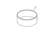
- the pneumatic tire 1 of FIG. 12 includes an annular structure 18 (see FIG. 13) instead of the belt layer 14 in the configuration of FIG.
- the pneumatic tire 1 includes a carcass layer 13, an annular structure 18 disposed outside the carcass layer 13 in the tire radial direction, and a tread rubber disposed outside the annular structure 18 in the tire radial direction.
- the annular structure 18 is embedded in the tread rubber 15 so as not to be exposed to the outside in the radial direction of the tread rubber 15.
- the outer peripheral surface of the annular structure 18 and the tire ground contact surface are arranged substantially in parallel.
- the annular structure 18 is made of metal and is 450 [N / m 2 ] or more and 2500 [N / m 2 ] or less, preferably 600 [N / m 2 ] or more and 2400 [N / m 2 ] or less, more preferably It has a tensile strength of 800 [N / m 2 ] or more and 2300 [N / m 2 ] or less. Thereby, the intensity
- a metal material for example, spring steel, high-tensile steel, stainless steel, or titanium (including a titanium alloy) can be employed. Of these, stainless steel is particularly preferable because it has high corrosion resistance and has a tensile strength in the above range.
- the annular structure 18 is manufactured from stainless steel
- the martensitic stainless steel, ferritic stainless steel, austenitic stainless steel, austenitic / ferritic duplex stainless steel, precipitation hardening stainless steel in the classification of JIS-G4303. Is preferably used.
- the tensile strength and toughness of the annular structure 18 can be improved.
- precipitation hardening stainless steel SUS631, SUS632J1 among the above stainless steels.
- the product of the tensile strength [MPa] and the thickness [mm] of the annular structure 18 is called a pressure resistance parameter.
- This pressure resistance parameter is a measure of resistance to the internal pressure of the pneumatic tire 1.
- the withstand voltage parameter is preferably 200 or more and 1700 or less, and 250 or more and 1600 or less.
- the pressure resistance parameter is preferably 200 or more and 1000 or less, and more preferably 250 or more and 950 or less.
- the pressure resistance parameter is preferably 300 or more and 1200 or less, and more preferably 350 or more and 1100 or less.
- the pressure resistance parameter is preferably 500 or more and 1700 or less, and more preferably 600 or more and 1600 or less.
- the elastic modulus of the annular structure 18 is preferably in the range of 70 [GPa] to 250 [GPa], and more preferably in the range of 80 [GPa] to 230 [GPa]. Moreover, it is preferable that the thickness of the annular structure 18 exists in the range of 0.1 [mm] or more and 0.8 [mm] or less. Thereby, the pressure resistance performance of the annular structure 18 and the durability against repeated bending can be ensured.
- the product of the elastic modulus and thickness of the annular structure 18 is called a stiffness parameter. At this time, the stiffness parameter is preferably in the range of 10 to 500, and more preferably in the range of 15 to 400.
- annular structure 18 may be configured by a single member formed integrally (see FIG. 13) or may be configured by joining a plurality of members (not shown).
- the belt layer 14 in the configuration of FIG. 2 can be omitted by arranging the annular structure 18 (see FIG. 13). Thereby, rolling resistance of a tire can be reduced and cornering power can be secured.
- the pneumatic tire 1 includes the carcass layer 13 and the sidewall rubber 16 disposed outside the carcass layer 13 in the tire width direction (see FIG. 2).
- the pneumatic tire 1 includes a resin coating 2 applied to a predetermined region A of the sidewall portion.
- the minimum value of the rubber wall thickness t of the sidewall portion in the region A to which the resin coating 2 is applied is in the range of 0.05 [mm] ⁇ t ⁇ 4.0 [mm].
- the thickness t of the rubber of the sidewall portion in the region A where the resin coating 2 is applied is optimized, so that there is an advantage that the rolling resistance of the tire can be reduced, and the cut resistance of the tire is improved.
- the rubber amount of the sidewall portion is reduced, and the rolling resistance of the tire is reduced.
- the resin coating 2 is applied to the sidewall portion, there is an advantage that the cut resistance of the sidewall portion is appropriately ensured. That is, when the thickness t of the rubber of the sidewall portion is reduced, the cut resistance of the sidewall portion is lowered. However, the resin coating 2 is applied to the sidewall portion, so that the cut resistance of the sidewall portion is appropriate. Secured.
- the thickness of the resin coating is in the range of 20 [ ⁇ m] to 300 [ ⁇ m].
- the thickness of the resin coating 2 is optimized. That is, when the thickness of the resin coating 2 is 20 [ ⁇ m] or more, the effect of maintaining the cut resistance of the sidewall portion by the resin coating 2 can be appropriately obtained. Further, when the thickness of the resin coating 2 is 300 [ ⁇ m] or less, the sidewall portion is thinned, and the rolling resistance of the tire is reduced.
- the breaking elongation of the sidewall rubber 16 is in the range of 200 [%] to 500 [%].
- the breaking elongation of the side wall rubber 16 is optimized. That is, when the elongation at break of the sidewall rubber 16 is 200 [%] or more, the durability of the sidewall rubber 16 against bending deformation is ensured. Moreover, the rigidity of a side wall part is ensured appropriately because the breaking elongation of the side wall rubber 16 is 500 [%] or less.
- the amount of the anti-aging agent added to the sidewall rubber 16 is in the range of 0.1 [parts by weight] to 2.0 [parts by weight].
- the pneumatic tire 1 includes a tire notation (not shown) attached to the region A where the resin coating 2 is applied by printing.
- the tire notation is given by printing, so that the air resistance of the sidewall portion can be reduced.
- the dynamic friction coefficient in the region A where the resin coating 2 is applied is 0.5 or less.
- the pneumatic tire 1 includes uneven portions 31 to 33 in a region A where the resin coating 2 is applied (see FIGS. 9 to 11).
- Such a configuration has an advantage that the occurrence of cracks in the resin coating 2 is suppressed because the uneven portions 31 to 33 relieve the tensile stress acting on the resin coating 2.
- the resin coating 2 is applied to a plurality of regions A divided (separated) in the tire circumferential direction or the tire radial direction (see FIGS. 4 to 8).
- the tensile stress acting on the resin coating 2 is relieved compared to a configuration in which the resin coating 2 is applied to a wide and annular region A that is continuous in the tire circumferential direction and the tire radial direction (see FIG. 1).
- production of the crack in the resin coating 2 is suppressed.
- the resin coating 2 includes a plurality of laminated coating layers (not shown). In such a configuration, there is an advantage that the function of the resin coating 2 is improved by optimizing the characteristics of each coating layer.
- the outermost coating layer constituting the resin coating 2 and the coating layer under the outermost layer have different colors (not shown).
- a different color coating layer underneath appears.
- the carcass layer 13 has an end portion 131 that is wound back outward in the tire width direction, and the end portion 131 of the carcass layer 13 is separated from the region A on which the resin coating 2 is applied. (See FIG. 2).
- the influence of the step due to the end 131 of the carcass layer 13 is reduced.
- the thickness of the resin coating 2 in the splice portion of the carcass layer 13 is equal to the resin coating in other portions of the region A. It is thinner than 2 (not shown).
- the thickness of the resin coating 2 in the splice portion of the carcass layer 13 thinner than the periphery, the difference in rigidity between the splice portion of the carcass layer 13 and the periphery can be canceled (relaxed). Thereby, there exists an advantage which the external appearance property of a tire improves.
- the pneumatic tire 1 includes a cylindrical annular structure 18 disposed so as to surround the outer periphery of the carcass layer 13 in the tire radial direction (see FIG. 12).
- the belt layer 14 in the configuration of FIG. 2 can be omitted by arranging the annular structure 18.
- the carcass layer 13 is made of aramid fibers.
- the method for manufacturing the pneumatic tire 1 includes a step of vulcanizing a green tire and a step of applying a resin coating 2 to the tire using the residual heat after the vulcanization (not shown). Thereby, there exists an advantage which can dry the resin coating 2 rapidly.
- the method of manufacturing the pneumatic tire 1 includes a step of filling a tire vulcanization mold with a green tire and vulcanization molding, and injecting a coating material into the tire vulcanization mold to resin the tire in the tire vulcanization mold.
- a step of applying the coating 2 (not shown).
- FIG. 14 is a chart showing the results of the performance test of the pneumatic tire according to the embodiment of the present invention.
- the resistance force at the time of drum diameter 1707 [mm], load 4.5 [kN], and speed 80 [km / h] is measured. Then, based on the measurement result, index evaluation using the conventional example as a reference (100) is performed. This evaluation is more preferable as the index value is smaller.
- the pneumatic tire 1 of Examples 1 and 2 has the configuration described in FIGS. 1 and 2 and includes a carcass layer 13 made of rayon fibers and a resin coating 2 made of urethane.
- the conventional pneumatic tire 1 does not have the resin coating 2 in the configuration shown in FIGS. 1 and 2.
Landscapes
- Engineering & Computer Science (AREA)
- Mechanical Engineering (AREA)
- Tires In General (AREA)
- Moulds For Moulding Plastics Or The Like (AREA)
- Heating, Cooling, Or Curing Plastics Or The Like In General (AREA)
Description
図1は、この発明の実施の形態にかかる空気入りタイヤ1を示す斜視図である。図2は、図1に記載した空気入りタイヤ1を示すタイヤ子午線方向の断面図である。同図は、空気入りタイヤ1の一例として、乗用車用タイヤを示している。なお、符号CLは、タイヤ赤道面である。
また、この空気入りタイヤ1は、樹脂コーティング(樹脂皮膜)2をサイドウォール部に備える(図1および図2参照)。
この空気入りタイヤ1の製造工程(図示省略)では、ビードコア11を構成するビードワイヤー、カーカス層13を構成するカーカスプライ、ベルト層14を構成するベルトプライ141、142、トレッドゴム15、サイドウォールゴム16、ビードゴム17などの各部材が成型機にかけられて、グリーンタイヤが成型される。次に、このグリーンタイヤがタイヤ加硫モールドに充填される。次に、この加硫モールドが加熱され、加圧装置によりグリーンタイヤが径方向外方に拡張されてタイヤ加硫モールドのタイヤ成形金型(トレッド面成形部)に当接する。次に、グリーンタイヤが加熱されることにより、トレッド部のゴム分子と硫黄分子とが結合して加硫が行われる。このとき、タイヤ成形金型の形状がグリーンタイヤのトレッド面に転写されて、空気入りタイヤ1のトレッドパターンが成形される。そして、成形されたタイヤがタイヤ加硫モールドから引き抜かれる。
図3~図11は、図1に記載した空気入りタイヤ1の変形例を示す説明図である。これらの図において、図1および図2に記載した空気入りタイヤ1と同一の構成要素には同一の符号を付し、その説明を省略する。
図12および図13は、図1に記載した空気入りタイヤ1の変形例を示す説明図である。これらの図において、図1および図2に記載した空気入りタイヤ1と同一の構成要素には同一の符号を付し、その説明を省略する。
以上説明したように、この空気入りタイヤ1は、カーカス層13と、カーカス層13のタイヤ幅方向外側に配置されたサイドウォールゴム16とを備える(図2参照)。また、空気入りタイヤ1は、サイドウォール部の所定の領域Aに施された樹脂コーティング2を備える。また、樹脂コーティング2を施した領域Aにおけるサイドウォール部のゴムの肉厚tの最小値が、0.05[mm]≦t≦4.0[mm]の範囲内にある。
Claims (16)
- カーカス層と、前記カーカス層のタイヤ幅方向外側に配置されたサイドウォールゴムとを備える空気入りタイヤであって、
サイドウォール部の所定の領域Aに施された樹脂コーティングを備え、且つ、前記樹脂コーティングを施した領域Aにおける前記サイドウォールゴムの肉厚tの最小値が、0.05[mm]≦t≦4.0[mm]の範囲内にあることを特徴とする空気入りタイヤ。 - 前記樹脂コーティングの厚さが、20[μm]以上300[μm]以下の範囲内にある請求項1に記載の空気入りタイヤ。
- 前記サイドウォールゴムの破断伸びが、200[%]以上500[%]以下の範囲内にある請求項1または2に記載の空気入りタイヤ。
- 前記サイドウォールゴムに対する老化防止剤の添加量が、0.1[重量部]以上2.0[重量部]以下の範囲内にある請求項1~3のいずれか一つに記載の空気入りタイヤ。
- 前記樹脂コーティングを施した領域Aに印刷により付されたタイヤ表記を備える請求項1~4のいずれか一つに記載の空気入りタイヤ。
- 前記樹脂コーティングを施した領域Aの動摩擦係数が、0.5以下である請求項1~5のいずれか一つに記載の空気入りタイヤ。
- 前記樹脂コーティングを施した領域Aに凹凸部を備える請求項1~6のいずれか一つに記載の空気入りタイヤ。
- 前記樹脂コーティングが、タイヤ周方向あるいはタイヤ径方向に分割された複数の領域Aに施工される請求項1~7のいずれか一つに記載の空気入りタイヤ。
- 前記樹脂コーティングが、積層された複数のコーティング層から成る請求項1~8のいずれか一つに記載の空気入りタイヤ。
- 前記樹脂コーティングを構成する最外層のコーティング層と、前記最外層の下層にあるコーティング層とが相互に異なる色彩を有する請求項9に記載の空気入りタイヤ。
- 前記カーカス層が、タイヤ幅方向外側に巻き返された端部を有すると共に、前記カーカス層の端部が、前記樹脂コーティングを施した領域Aから外れた位置に配置される請求項1~10のいずれか一つに記載の空気入りタイヤ。
- 前記カーカス層のスプライス部における前記樹脂コーティングの厚さが、領域Aの他の部分における前記樹脂コーティングの厚さよりも薄い請求項1~11のいずれか一つに記載の空気入りタイヤ。
- 前記カーカス層のタイヤ径方向の外周を囲んで配置される円筒形状の環状構造体を備える請求項1~12のいずれか一つに記載の空気入りタイヤ。
- 前記カーカス層が、アラミド繊維から成る請求項1~13のいずれか一つに記載の空気入りタイヤ。
- 請求項1~14のいずれか一つに記載の空気入りタイヤの製造方法であって、
グリーンタイヤを加硫成形するステップと、前記加硫成形後の余熱を用いてタイヤに前記樹脂コーティングを施工するステップとを備えることを特徴とする空気入りタイヤの製造方法。 - 請求項1~14のいずれか一つに記載の空気入りタイヤの製造方法であって、
グリーンタイヤをタイヤ加硫モールドに充填して加硫成形するステップと、前記タイヤ加硫モールドにコーティング材を注入して前記タイヤ加硫モールド内のタイヤに前記樹脂コーティングを施工するステップとを備えることを特徴とする空気入りタイヤの製造方法。
Priority Applications (5)
| Application Number | Priority Date | Filing Date | Title |
|---|---|---|---|
| DE112013001061.5T DE112013001061T5 (de) | 2012-02-21 | 2013-02-20 | Luftreifen und Verfahren zum Herstellen eines Luftreifens |
| JP2014500742A JP6197786B2 (ja) | 2012-02-21 | 2013-02-20 | 空気入りタイヤおよび空気入りタイヤの製造方法 |
| CN201380010210.2A CN104125888B (zh) | 2012-02-21 | 2013-02-20 | 充气轮胎及充气轮胎的制造方法 |
| US14/380,059 US10017014B2 (en) | 2012-02-21 | 2013-02-20 | Pneumatic tire and method of manufacturing pneumatic tire |
| US16/004,266 US11458778B2 (en) | 2012-02-21 | 2018-06-08 | Pneumatic tire and method of manufacturing pneumatic tire |
Applications Claiming Priority (2)
| Application Number | Priority Date | Filing Date | Title |
|---|---|---|---|
| JP2012-035451 | 2012-02-21 | ||
| JP2012035451 | 2012-02-21 |
Related Child Applications (2)
| Application Number | Title | Priority Date | Filing Date |
|---|---|---|---|
| US14/380,059 A-371-Of-International US10017014B2 (en) | 2012-02-21 | 2013-02-20 | Pneumatic tire and method of manufacturing pneumatic tire |
| US16/004,266 Division US11458778B2 (en) | 2012-02-21 | 2018-06-08 | Pneumatic tire and method of manufacturing pneumatic tire |
Publications (1)
| Publication Number | Publication Date |
|---|---|
| WO2013125592A1 true WO2013125592A1 (ja) | 2013-08-29 |
Family
ID=49005774
Family Applications (1)
| Application Number | Title | Priority Date | Filing Date |
|---|---|---|---|
| PCT/JP2013/054204 Ceased WO2013125592A1 (ja) | 2012-02-21 | 2013-02-20 | 空気入りタイヤおよび空気入りタイヤの製造方法 |
Country Status (5)
| Country | Link |
|---|---|
| US (2) | US10017014B2 (ja) |
| JP (1) | JP6197786B2 (ja) |
| CN (1) | CN104125888B (ja) |
| DE (1) | DE112013001061T5 (ja) |
| WO (1) | WO2013125592A1 (ja) |
Cited By (6)
| Publication number | Priority date | Publication date | Assignee | Title |
|---|---|---|---|---|
| WO2015129160A1 (ja) * | 2014-02-26 | 2015-09-03 | 株式会社ブリヂストン | タイヤ |
| JP2017105375A (ja) * | 2015-12-11 | 2017-06-15 | 株式会社ブリヂストン | タイヤ |
| US20170210183A1 (en) * | 2014-07-30 | 2017-07-27 | Bridgestone Corporation | Tire |
| JP2017193309A (ja) * | 2016-04-22 | 2017-10-26 | 株式会社ブリヂストン | タイヤ |
| JP2018095111A (ja) * | 2016-12-14 | 2018-06-21 | 株式会社ブリヂストン | タイヤ |
| JP2019055535A (ja) * | 2017-09-21 | 2019-04-11 | 住友ゴム工業株式会社 | タイヤ加硫金型 |
Families Citing this family (5)
| Publication number | Priority date | Publication date | Assignee | Title |
|---|---|---|---|---|
| DE102017210403A1 (de) * | 2017-06-21 | 2018-12-27 | Continental Reifen Deutschland Gmbh | Elastomerprodukt aufweisend eine Markierung und Verfahren zur Herstellung |
| US20200361249A1 (en) * | 2017-12-25 | 2020-11-19 | The Yokohama Rubber Co., Ltd. | Pneumatic Tire |
| FR3083742B1 (fr) * | 2018-07-11 | 2020-07-17 | Compagnie Generale Des Etablissements Michelin | Pneumatique comportant des flancs renforces |
| FR3096933B1 (fr) * | 2019-06-06 | 2021-05-14 | Michelin & Cie | Pneumatique comportant des flancs optimises et une armature de sommet constituee de deux couches de sommet de travail et d’une couche d’elements de renforcement circonferentiels |
| DE102020205745A1 (de) | 2020-05-07 | 2021-11-11 | Continental Reifen Deutschland Gmbh | Fahrzeugluftreifen |
Citations (11)
| Publication number | Priority date | Publication date | Assignee | Title |
|---|---|---|---|---|
| JPH01240307A (ja) * | 1988-03-22 | 1989-09-25 | Yokohama Rubber Co Ltd:The | 空気入りラジアルタイヤ |
| JPH11286203A (ja) * | 1998-02-05 | 1999-10-19 | Yokohama Rubber Co Ltd:The | 空気入りタイヤ |
| JP2000142039A (ja) * | 1998-11-11 | 2000-05-23 | Bridgestone Corp | 重荷重用空気入りラジアルタイヤ |
| JP2000177315A (ja) * | 1998-12-17 | 2000-06-27 | Bridgestone Corp | 空気入りタイヤ用のバンド部材 |
| JP2000510191A (ja) * | 1996-10-02 | 2000-08-08 | ピレリ・ライフェンヴェルケ・ゲーエムベーハー・ウント・コンパニー・カーゲー | 特にタイヤなどのゴム製品上にマーキングを印刷する方法 |
| JP2004050985A (ja) * | 2002-07-22 | 2004-02-19 | Bridgestone Corp | 空気入りタイヤおよびそれの製造方法 |
| JP2006123704A (ja) * | 2004-10-28 | 2006-05-18 | Yokohama Rubber Co Ltd:The | 空気入りタイヤ |
| JP2007331422A (ja) * | 2006-06-12 | 2007-12-27 | Bridgestone Corp | 空気入りラジアルタイヤ |
| JP2010030527A (ja) * | 2008-07-30 | 2010-02-12 | Sumitomo Rubber Ind Ltd | ランフラットタイヤ |
| JP2010137604A (ja) * | 2008-12-09 | 2010-06-24 | Toyo Tire & Rubber Co Ltd | 空気入りタイヤ |
| JP2012006452A (ja) * | 2010-06-23 | 2012-01-12 | Yokohama Rubber Co Ltd:The | 空気入りタイヤ |
Family Cites Families (28)
| Publication number | Priority date | Publication date | Assignee | Title |
|---|---|---|---|---|
| US2761489A (en) * | 1953-03-06 | 1956-09-04 | Gen Tire & Rubber Co | Method of manufacture of a pneumatic tire |
| JPS5237303A (en) * | 1975-09-18 | 1977-03-23 | Bridgestone Corp | Light air tire having thin side wall rubber and method of fabricating the same |
| GB2034603A (en) * | 1978-07-19 | 1980-06-11 | Bell R | Tyres |
| US4253513A (en) * | 1979-10-01 | 1981-03-03 | The Goodyear Tire & Rubber Company | Cast tire and method of manufacture |
| US4854361A (en) * | 1986-06-24 | 1989-08-08 | The Goodyear Tire & Rubber Company | Pneumatic tires |
| US5149591A (en) * | 1991-03-28 | 1992-09-22 | The Goodyear Tire & Rubber Company | Blends of polyvinyl alcohol and polyurethane water dispersions for increased humidity resistance of water soluble white sidewall paints |
| AU647984B2 (en) * | 1992-01-29 | 1994-03-31 | Bridgestone Corporation | Pneumatic radial tires |
| JP3151035B2 (ja) | 1992-03-05 | 2001-04-03 | 株式会社ブリヂストン | 空気入りラジアルタイヤ |
| JP3234646B2 (ja) | 1992-08-14 | 2001-12-04 | 株式会社ブリヂストン | 空気入りタイヤの製造方法 |
| US5315764A (en) * | 1992-12-07 | 1994-05-31 | Robbins Jimmy H | Method and apparatus for applying alphanumeric characters to the sidwall of a tire |
| US5645661A (en) * | 1995-11-09 | 1997-07-08 | The Goodyear Tire & Rubber Company | Tire sidewall |
| EP0991530B1 (en) * | 1997-06-09 | 2004-09-22 | InMat, L.L.C. | Barrier coating of a polymer and a dispersed layered filler, a method of coatingparticles with said barrier coating and coated compositions, particulary tires. |
| US6223797B1 (en) * | 1998-01-29 | 2001-05-01 | The Yokohama Rubber Co. | Pneumatic tire with specified rubber properties |
| US6223796B1 (en) * | 1999-08-17 | 2001-05-01 | The Goodyear Tire & Rubber Company | Pneumatic tire having an outer layer of veneer covering the sidewall |
| DE10004439C2 (de) * | 2000-02-02 | 2002-08-01 | Continental Ag | Fahrzeugreifen |
| CN1294987A (zh) | 2000-12-09 | 2001-05-16 | 沈德 | 一种迷彩轮胎及其生产方法 |
| JP2004058752A (ja) | 2002-07-26 | 2004-02-26 | Noboru Miyabe | サイドウォールにバリヤコート剤を塗布したタイヤ |
| WO2007071272A1 (en) | 2005-12-21 | 2007-06-28 | Pirelli Tyre S.P.A. | Tire having a colored surface |
| BRPI0621708B1 (pt) * | 2006-05-31 | 2018-01-02 | Pirelli Tyre S.P.A. | Pneu compreendendo pelo menos um elemento estrutural externo, kit para tratamento de superfície de artigos elastoméricos reticulados, artigo manufaturado reticulado, e, método para aplicar uma composição reticulável |
| US9037388B2 (en) * | 2006-11-17 | 2015-05-19 | Mccrary Personal Transport System, Llc | Intelligent public transit system using dual-mode vehicles |
| JP4901591B2 (ja) | 2007-06-08 | 2012-03-21 | 住友ゴム工業株式会社 | サイドウォール用ゴム組成物およびそれを用いた空気入りタイヤ |
| CN101802078B (zh) * | 2007-10-03 | 2013-05-01 | 住友橡胶工业株式会社 | 胎侧用橡胶组合物及具有使用该组合物的胎侧的轮胎、以及胎搭接部用橡胶组合物及具有使用胎搭接部用橡胶组合物的胎搭接部的轮胎 |
| JP4638933B2 (ja) * | 2007-12-07 | 2011-02-23 | 住友ゴム工業株式会社 | タイヤ用ゴム組成物 |
| JP4435253B2 (ja) | 2008-03-26 | 2010-03-17 | 住友ゴム工業株式会社 | インナーライナーおよび空気入りタイヤ |
| JP5225735B2 (ja) * | 2008-04-21 | 2013-07-03 | 東洋ゴム工業株式会社 | 空気入りタイヤ及びその製造方法 |
| JP2010111351A (ja) * | 2008-11-10 | 2010-05-20 | Yokohama Rubber Co Ltd:The | 空気入りタイヤ |
| JP5436303B2 (ja) * | 2010-03-30 | 2014-03-05 | 株式会社ブリヂストン | タイヤ、及び、タイヤの製造方法 |
| JP5769583B2 (ja) * | 2011-10-21 | 2015-08-26 | 株式会社ブリヂストン | 空気入りタイヤ |
-
2013
- 2013-02-20 WO PCT/JP2013/054204 patent/WO2013125592A1/ja not_active Ceased
- 2013-02-20 JP JP2014500742A patent/JP6197786B2/ja active Active
- 2013-02-20 CN CN201380010210.2A patent/CN104125888B/zh active Active
- 2013-02-20 US US14/380,059 patent/US10017014B2/en active Active
- 2013-02-20 DE DE112013001061.5T patent/DE112013001061T5/de active Pending
-
2018
- 2018-06-08 US US16/004,266 patent/US11458778B2/en active Active
Patent Citations (11)
| Publication number | Priority date | Publication date | Assignee | Title |
|---|---|---|---|---|
| JPH01240307A (ja) * | 1988-03-22 | 1989-09-25 | Yokohama Rubber Co Ltd:The | 空気入りラジアルタイヤ |
| JP2000510191A (ja) * | 1996-10-02 | 2000-08-08 | ピレリ・ライフェンヴェルケ・ゲーエムベーハー・ウント・コンパニー・カーゲー | 特にタイヤなどのゴム製品上にマーキングを印刷する方法 |
| JPH11286203A (ja) * | 1998-02-05 | 1999-10-19 | Yokohama Rubber Co Ltd:The | 空気入りタイヤ |
| JP2000142039A (ja) * | 1998-11-11 | 2000-05-23 | Bridgestone Corp | 重荷重用空気入りラジアルタイヤ |
| JP2000177315A (ja) * | 1998-12-17 | 2000-06-27 | Bridgestone Corp | 空気入りタイヤ用のバンド部材 |
| JP2004050985A (ja) * | 2002-07-22 | 2004-02-19 | Bridgestone Corp | 空気入りタイヤおよびそれの製造方法 |
| JP2006123704A (ja) * | 2004-10-28 | 2006-05-18 | Yokohama Rubber Co Ltd:The | 空気入りタイヤ |
| JP2007331422A (ja) * | 2006-06-12 | 2007-12-27 | Bridgestone Corp | 空気入りラジアルタイヤ |
| JP2010030527A (ja) * | 2008-07-30 | 2010-02-12 | Sumitomo Rubber Ind Ltd | ランフラットタイヤ |
| JP2010137604A (ja) * | 2008-12-09 | 2010-06-24 | Toyo Tire & Rubber Co Ltd | 空気入りタイヤ |
| JP2012006452A (ja) * | 2010-06-23 | 2012-01-12 | Yokohama Rubber Co Ltd:The | 空気入りタイヤ |
Cited By (7)
| Publication number | Priority date | Publication date | Assignee | Title |
|---|---|---|---|---|
| WO2015129160A1 (ja) * | 2014-02-26 | 2015-09-03 | 株式会社ブリヂストン | タイヤ |
| JP2015160488A (ja) * | 2014-02-26 | 2015-09-07 | 株式会社ブリヂストン | タイヤ |
| US20170210183A1 (en) * | 2014-07-30 | 2017-07-27 | Bridgestone Corporation | Tire |
| JP2017105375A (ja) * | 2015-12-11 | 2017-06-15 | 株式会社ブリヂストン | タイヤ |
| JP2017193309A (ja) * | 2016-04-22 | 2017-10-26 | 株式会社ブリヂストン | タイヤ |
| JP2018095111A (ja) * | 2016-12-14 | 2018-06-21 | 株式会社ブリヂストン | タイヤ |
| JP2019055535A (ja) * | 2017-09-21 | 2019-04-11 | 住友ゴム工業株式会社 | タイヤ加硫金型 |
Also Published As
| Publication number | Publication date |
|---|---|
| CN104125888B (zh) | 2017-09-01 |
| US11458778B2 (en) | 2022-10-04 |
| US10017014B2 (en) | 2018-07-10 |
| JPWO2013125592A1 (ja) | 2015-07-30 |
| US20180290502A1 (en) | 2018-10-11 |
| DE112013001061T5 (de) | 2014-10-30 |
| CN104125888A (zh) | 2014-10-29 |
| JP6197786B2 (ja) | 2017-09-20 |
| US20150041038A1 (en) | 2015-02-12 |
Similar Documents
| Publication | Publication Date | Title |
|---|---|---|
| JP6197786B2 (ja) | 空気入りタイヤおよび空気入りタイヤの製造方法 | |
| JP5974897B2 (ja) | 空気入りタイヤ | |
| JP6467949B2 (ja) | 空気入りタイヤ | |
| WO2014010351A1 (ja) | 空気入りタイヤ | |
| US11173756B2 (en) | Pneumatic tire | |
| EP3459763A1 (en) | Tire | |
| CN106457903A (zh) | 实心轮胎 | |
| JP6269306B2 (ja) | 更生タイヤ | |
| WO2014203908A1 (ja) | 空気入りタイヤ | |
| JP6015450B2 (ja) | 空気入りタイヤ | |
| US9840114B2 (en) | Pneumatic radial tire for a passenger car having ultra fine steel cords for a carcass ply | |
| US9950570B2 (en) | Pneumatic tire | |
| JP2013112131A (ja) | 空気入りタイヤ | |
| JP6665530B2 (ja) | 空気入りタイヤ | |
| JP5437172B2 (ja) | 空気入りタイヤ | |
| EP3795381A1 (en) | Pneumatic tyre | |
| JP2015174459A (ja) | 空気入りタイヤ | |
| JP2012025202A (ja) | 空気入りラジアルタイヤ | |
| JP5091599B2 (ja) | 空気入りタイヤ及びその製造方法 | |
| AU2017411632A1 (en) | Bias tire | |
| JP5978786B2 (ja) | プレキュア更生タイヤ | |
| WO2014192962A1 (ja) | タイヤ及びタイヤの製造方法 | |
| WO2020084830A1 (ja) | 空気入りタイヤ | |
| WO2019239895A1 (ja) | 空気入りタイヤ | |
| WO2020084832A1 (ja) | 空気入りタイヤ |
Legal Events
| Date | Code | Title | Description |
|---|---|---|---|
| 121 | Ep: the epo has been informed by wipo that ep was designated in this application |
Ref document number: 13751677 Country of ref document: EP Kind code of ref document: A1 |
|
| ENP | Entry into the national phase |
Ref document number: 2014500742 Country of ref document: JP Kind code of ref document: A |
|
| WWE | Wipo information: entry into national phase |
Ref document number: 14380059 Country of ref document: US |
|
| WWE | Wipo information: entry into national phase |
Ref document number: 1120130010615 Country of ref document: DE Ref document number: 112013001061 Country of ref document: DE |
|
| 122 | Ep: pct application non-entry in european phase |
Ref document number: 13751677 Country of ref document: EP Kind code of ref document: A1 |