WO2013125627A1 - 自転車用トレーナ - Google Patents
自転車用トレーナ Download PDFInfo
- Publication number
- WO2013125627A1 WO2013125627A1 PCT/JP2013/054308 JP2013054308W WO2013125627A1 WO 2013125627 A1 WO2013125627 A1 WO 2013125627A1 JP 2013054308 W JP2013054308 W JP 2013054308W WO 2013125627 A1 WO2013125627 A1 WO 2013125627A1
- Authority
- WO
- WIPO (PCT)
- Prior art keywords
- bicycle
- support shaft
- elastic
- bicycle trainer
- frame
- Prior art date
- Legal status (The legal status is an assumption and is not a legal conclusion. Google has not performed a legal analysis and makes no representation as to the accuracy of the status listed.)
- Ceased
Links
Images


Classifications
-
- A—HUMAN NECESSITIES
- A63—SPORTS; GAMES; AMUSEMENTS
- A63B—APPARATUS FOR PHYSICAL TRAINING, GYMNASTICS, SWIMMING, CLIMBING, OR FENCING; BALL GAMES; TRAINING EQUIPMENT
- A63B22/00—Exercising apparatus specially adapted for conditioning the cardio-vascular system, for training agility or co-ordination of movements
- A63B22/06—Exercising apparatus specially adapted for conditioning the cardio-vascular system, for training agility or co-ordination of movements with support elements performing a rotating cycling movement, i.e. a closed path movement
- A63B22/0605—Exercising apparatus specially adapted for conditioning the cardio-vascular system, for training agility or co-ordination of movements with support elements performing a rotating cycling movement, i.e. a closed path movement performing a circular movement, e.g. ergometers
-
- A—HUMAN NECESSITIES
- A63—SPORTS; GAMES; AMUSEMENTS
- A63B—APPARATUS FOR PHYSICAL TRAINING, GYMNASTICS, SWIMMING, CLIMBING, OR FENCING; BALL GAMES; TRAINING EQUIPMENT
- A63B21/00—Exercising apparatus for developing or strengthening the muscles or joints of the body by working against a counterforce, with or without measuring devices
- A63B21/02—Exercising apparatus for developing or strengthening the muscles or joints of the body by working against a counterforce, with or without measuring devices using resilient force-resisters
- A63B21/026—Bars; Tubes; Leaf springs
-
- A—HUMAN NECESSITIES
- A63—SPORTS; GAMES; AMUSEMENTS
- A63B—APPARATUS FOR PHYSICAL TRAINING, GYMNASTICS, SWIMMING, CLIMBING, OR FENCING; BALL GAMES; TRAINING EQUIPMENT
- A63B69/00—Training appliances or apparatus for special sports
- A63B69/16—Training appliances or apparatus for special sports for cycling, i.e. arrangements on or for real bicycles
-
- A—HUMAN NECESSITIES
- A63—SPORTS; GAMES; AMUSEMENTS
- A63B—APPARATUS FOR PHYSICAL TRAINING, GYMNASTICS, SWIMMING, CLIMBING, OR FENCING; BALL GAMES; TRAINING EQUIPMENT
- A63B69/00—Training appliances or apparatus for special sports
- A63B69/16—Training appliances or apparatus for special sports for cycling, i.e. arrangements on or for real bicycles
- A63B2069/161—Training appliances or apparatus for special sports for cycling, i.e. arrangements on or for real bicycles supports for the front of the bicycle
- A63B2069/162—Training appliances or apparatus for special sports for cycling, i.e. arrangements on or for real bicycles supports for the front of the bicycle for front fork or handlebar
-
- A—HUMAN NECESSITIES
- A63—SPORTS; GAMES; AMUSEMENTS
- A63B—APPARATUS FOR PHYSICAL TRAINING, GYMNASTICS, SWIMMING, CLIMBING, OR FENCING; BALL GAMES; TRAINING EQUIPMENT
- A63B69/00—Training appliances or apparatus for special sports
- A63B69/16—Training appliances or apparatus for special sports for cycling, i.e. arrangements on or for real bicycles
- A63B2069/164—Training appliances or apparatus for special sports for cycling, i.e. arrangements on or for real bicycles supports for the rear of the bicycle, e.g. for the rear forks
- A63B2069/165—Training appliances or apparatus for special sports for cycling, i.e. arrangements on or for real bicycles supports for the rear of the bicycle, e.g. for the rear forks rear wheel hub supports
-
- A—HUMAN NECESSITIES
- A63—SPORTS; GAMES; AMUSEMENTS
- A63B—APPARATUS FOR PHYSICAL TRAINING, GYMNASTICS, SWIMMING, CLIMBING, OR FENCING; BALL GAMES; TRAINING EQUIPMENT
- A63B26/00—Exercising apparatus not covered by groups A63B1/00 - A63B25/00
- A63B26/003—Exercising apparatus not covered by groups A63B1/00 - A63B25/00 for improving balance or equilibrium
Definitions
- the present invention relates to a bicycle trainer that can perform training using an actual bicycle that travels outdoors, and more particularly, to a bicycle trainer that is used for training with the bicycle wheel removed.
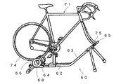
- a frame 62 on which a bicycle from which the front wheels are removed can be mounted is provided.
- the frame 62 includes a roller 64 that rotates while contacting a tire 74 of the rear wheel of the bicycle, and a roller 64.
- a bicycle trainer 60 provided with resistance applying means 66 that provides resistance to rotation is known (see Patent Document 1).
- a main body portion 82 that is stably installed on the ground, and a frame end fixing that supports and fixes the front frame end portion 95 of the bicycle 91 from which the rear wheel is removed.
- a bicycle training device 80 comprising means 85, a rotating body 84 linked to the driving device 92 of the bicycle 91 and rotating following the driving device 92, and a rotation braking device 88 for controlling the rotation of the rotating body 84.
- the front wheel of the bicycle 91 is removed from the fork end portion 95 together with the hub and supported and fixed to the fork end fixing means 85.
- Patent Document 1 The invention described in Patent Document 1 can be varied in a wide range from a state where no braking force to be applied to the braking disk 68 is received to a state where a predetermined braking force is received.
- the bicycle trainer 60 in which the front fork end portion 75 of the bicycle is supported and fixed to the hawk clamper 65 provided at the front rising portion 63 of the frame 62, the bicycle is moved back and forth like when actually running outdoors. Since it does not move or tilt left and right, there is a problem that it lacks a feeling of actual running as when actually driving a bicycle.
- Patent Document 2 the configuration in which the front fork end portion 95 of the bicycle 91 to be mounted is attached to the main body portion 82 via the fork end fixing means 85 is the same as that of Patent Document 1, and actually The problem of lacking a sense of actual driving like driving a bicycle outdoors has not been solved.
- the present invention has been made in view of the above-described circumstances, and an object of the present invention is to provide a bicycle trainer that provides a riding comfort as when a bicycle is actually driven outdoors.
- a bicycle trainer is a bicycle trainer that can perform training using a detachably mounted bicycle (21), and is a main body unit placed on a floor. (3), a support shaft (5) having one end loosely inserted into the main body and the other end fixed to a fork end support means (7) for supporting the fork end portion (23) of the bicycle; An elastic part (9) disposed so as to surround at least a part of the other end side from the longitudinal center of the shaft, and the bicycle is elastically deformed by a force applied from the fork end part. It is characterized by being able to move back and forth and tilt left and right.
- the upper portion of the support shaft one end of which is loosely inserted into the main body portion and the other end is fixed to the fork end support means, is surrounded by the elastic portion.
- the shaft is elastically deformed. For this reason, it is possible to feel the swing of the bicycle from front to back and from side to side corresponding to the force applied to the bicycle.
- the bicycle trainer according to the present invention has a cylindrical hollow portion therein, and includes a frame portion (11) erected on the main body portion, and the elastic portion is formed on a cylindrical inner surface of the frame portion.
- the support shaft is inserted through the elastic portion into the hollow portion along the longitudinal direction of the frame portion, and the other end extends from the frame portion.
- a spindle is arrange
- an aesthetics improves.
- the elastic portion is formed on the cylindrical inner surface of the frame portion, the swinging of the support shaft in the front-rear and left-right directions can be limited to a certain range. This makes it possible to limit the maximum swing angle in the front / rear / left / right direction of the bicycle to the maximum angle during actual driving.
- the support shaft is preferably a steel rod or a steel pipe. Since the support shaft is a steel rod or a steel pipe, the strength is strong and elastic, so the strength of the bicycle trainer is increased and the performance of swinging the bicycle back and forth and right and left is also improved.
- the support shaft may include an elastic member having elasticity.
- an elastic member having elasticity for example, a spring can be used. As a result, the swinging of the bicycle from front to back and from side to side can be appropriately adjusted.
- the support shaft has a support shaft portion in which connecting portions made of the elastic member and the inelastic member are alternately connected.
- the non-elastic member refers to a member that does not substantially have elasticity, and examples thereof include a metal material.
- the elastic modulus of the elastic material constituting the elastic member gradually decreases from one end to the other end of the support shaft.
- the upper part of the support shaft one end of which is loosely inserted into the main body and the other end fixed to the fork end support means, is surrounded by the elastic portion, and the support shaft is separated from the fork end of the bicycle.
- the train is elastically deformed by the applied force, and when the bicycle is worn and trained, the bicycle swings back and forth and left and right through the fork end, so trainers can actually run as if driving a bicycle outdoors. A feeling is given.
- FIG. 10 is an upper cross-sectional view of a frame portion according to a modification example of Example 2. It is explanatory drawing which shows a part of spindle of the bicycle trainer which concerns on Example 3. FIG. It is explanatory drawing which shows a prior art example. It is explanatory drawing which shows a prior art example.
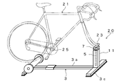
- FIG. 1 shows a bicycle trainer 10 according to a first embodiment.
- the body 3 of the bicycle trainer 10 includes a front-rear heel 3 a that extends horizontally in the front-rear direction, a rear leg 3 b that extends in the left-right direction at the rear portion of the front-rear heel 3 a, and a front-rear heel 3 a.
- a front leg 3c extending in the left-right direction is provided at the front portion.
- a rotating body 6 that rotates in contact with the outer periphery of the rear wheel 27 of the bicycle 21 is attached to the rear portion of the front / rear direction rod 3a.
- the rotating body 6 is composed of a roller member 6a having a predetermined outer diameter. It is supported by the main body 3 via a bracket (not shown).
- the support shaft 5 has a rod shape, and one end thereof is inserted into a hole (not shown) provided in a support shaft mounting base (not shown) fixed to the front-rear direction flange 3a, and the other end is fork end support means 7. It is fixed to.
- the bicycle 21 is mounted on the bicycle trainer 10 by attaching the fork end portion 23 of the bicycle 21 with the front wheel removed to the fork end support means 7.
- the outer peripheral surface is surrounded by the elastic portion 9, and the elastic portion 9 is elastic material such as natural rubber or synthetic rubber having elasticity. Consists of.
- the horizontal section of the elastic portion 9 is annular, its inner peripheral surface is in contact with the outer peripheral surface of the support shaft 5, and its outer surface is the inner surface of a short metal tube (about 2 to 3 cm, not shown). It touches.
- the metal tube is attached to the main body 3 by four fixing members 8a, 8b, 8c, and 8d fixed to the front portion of the front-rear flange 3a and the front leg 3c, respectively.
- the support shaft 5 is a stainless steel pipe.
- the bicycle training apparatus 10 performs training by attaching a bicycle 21 from which at least the front wheel is removed and applying a load to the pedal 28. Placed stably.
- the front wheel of the bicycle 21 is removed from the frame end portion 23 together with its axle (hub), and the frame end portion 23 is attached to the frame of the bicycle training device 10. It is supported by the end fixing means 7.
- the rear wheel 27 is placed on the roller member 6 a of the rotating body 6 provided at the rear portion of the training apparatus 10.
- This force is a force that pushes and bends the support shaft 5 forward.
- the upper portion of the support shaft 5 near the frame end fixing means 7) is placed in a frame (metal tube) whose periphery is fixed to the main body 3. Since it is surrounded by the provided elastic portion 9, the force for bending the support shaft 5 is limited.
- the support shaft 5 bends to a certain extent by the force thus limited, and the bicycle 21 tilts forward appropriately. Also, if the trainee applies a force and tilts the bicycle 21 to the left or right assuming that it turns left or right, the support shaft 5 is similarly bent to a certain degree by the left or right force, and the bicycle 21 is moderate. Lean left or right.
- the bicycle 21 when the trainee tries to move the bicycle 21 back and forth and left and right, the bicycle 21 also moves back and forth or tilts left and right as if actually training outdoors. It becomes possible to move.
- the swing angle is set to a maximum inclination angle when the bicycle 21 is actually driven straight ahead outdoors, for example, 5 degrees or less with respect to a line perpendicular to the floor on which the main body 3 is placed.
- the elastic modulus of the elastic material constituting the elastic portion 9 (longitudinal elastic modulus or Young's modulus), the size of the elastic portion 9, or the position of the support shaft 5 to which the elastic portion 9 is attached.
- FIG. 2 shows a bicycle trainer 20 according to the second embodiment.
- the bicycle trainer 20 is different from the first embodiment in that the frame portion 11 is erected at the front portion of the front-rear direction rod 3a.
- the frame part 11 has a cylindrical hollow part (not shown) inside, and the support shaft 5 is disposed therein.
- the upper end (the other end) of the support shaft 5 extends from the frame portion 11, and the fork end support means 7 is fixed to the other end.
- the fork end portion 23 of the bicycle 21 is attached to the fork end support means 7 by front fork claws (not shown).
- Other structures are the same as those of the bicycle trainer 10 of the first embodiment.
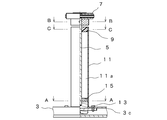
- FIG. 3 is a one-side longitudinal sectional view of the frame portion 11 and the fork end support means 7 according to the second embodiment as viewed from the front direction (the right side of the paper surface of FIG. 2).
- the frame part 11 has a cylindrical hollow part 11a inside, and a support shaft 5 is accommodated in the longitudinal direction at the center of the hollow part 11a.
- a lower portion of the frame portion 11 is inserted into a support bearing 15 fixed to the front leg 3c with bolts 13 and 13, and an upper portion thereof is covered with an elastic portion 9 having a predetermined thickness, and the center of the elastic portion 9 is supported by a support shaft.
- the upper end (the other end) of the support shaft 5 is fixed to the fork end support means 7.
- the lower portion of the support shaft 5 is inserted into a hole 15 a provided in the support bearing 15 in a state where the support shaft 5 can swing and move back and forth and right and left.
- the material of the support bearing 15 is aluminum
- the support shaft 5 is a cylindrical steel material made of stainless steel.
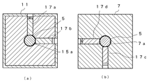
- FIG. 4A and 4B are cross-sectional views taken along lines AA and BB in FIG. 3, respectively.
- the frame portion 11 is inserted into the support bearing 15, and the support shaft 5 is inserted into a hole 15 a opened in the center of the support bearing 15.
- the position of the support shaft 5 can be adjusted by the tightening degree of the screws 17a and 17b.
- the lower portion of the fork end support means 7 has a quadrangular cross section, a hole 7a is provided at the center thereof, and the support shaft 5 is inserted into the hole 7a from its upper end.
- the position of the support shaft 5 can be adjusted by the tightening degree of the screws 17c and 17d.
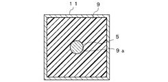
- FIG. 5 is a cross-sectional view taken along the line CC of FIG.
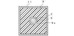
- the elastic part 9 is provided in the upper part of the frame part 11, the hole 9a is opened in the center of the elastic part 9, and the spindle 5 has penetrated this hole 9a.
- an elastomer elastomer
- the elastic portion 9 is provided in the upper portion of the hollow portion of the frame portion 11 and the support shaft 5 penetrates the center thereof. Can be limited to. The degree can be adjusted by selecting characteristics of the elastic material constituting the elastic portion 9 (for example, longitudinal elastic modulus or Young's modulus).
- Example 2- there may be a gap S between the elastic portion 9 and the support shaft 5 without the elastic portion 9 and the outer peripheral surface of the support shaft 5 being in contact with each other. With such a structure, the bending state of the support shaft 5 is adjusted by the elastic portion 9.
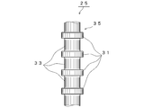
- FIG. 7 shows a part of the support shaft of the bicycle trainer according to the third embodiment.
- the support shaft 25 has a support shaft portion 35 having a rod-like structure in which elastic members 33 and connecting portions 31 made of a metal material are alternately arranged.
- the elastic member 33 is made of an elastic material such as elastic natural rubber or synthetic rubber, and the connecting portion 31 is made of a metal material such as stainless steel and is welded to the elastic member 33.
- the elastic member 33 when the support shaft 25 is attached to the main body (not shown) of the bicycle trainer, the elastic member 33 is configured from the main body side (one end) to the upper end (the other end) of the support shaft 25. The elastic modulus of the elastic material is successively decreased.
- the bicycle trainer according to the present invention is not limited to the above-described embodiment, and can take various configurations without departing from the gist of the present invention.
- the support shaft 5 may be an elastic member having elasticity such as a spring.
- the elastic portion 9 may be provided in the entire hollow portion of the frame portion 11.
- the bicycle trainer according to the present invention can be used outdoors in indoor training, which tends to be monotonous, because the bicycle moves back and forth and tilts left and right in response to the force of stepping on the pedal or the force of bending the bicycle left and right. It is useful as a training device that can train while obtaining the same feel as in running. Therefore, it is also suitable for a training apparatus for athletes who need endurance and strong strength training.
Landscapes
- Health & Medical Sciences (AREA)
- General Health & Medical Sciences (AREA)
- Physical Education & Sports Medicine (AREA)
- Life Sciences & Earth Sciences (AREA)
- Biophysics (AREA)
- Orthopedic Medicine & Surgery (AREA)
- Cardiology (AREA)
- Vascular Medicine (AREA)
- Motorcycle And Bicycle Frame (AREA)
- Steering Devices For Bicycles And Motorcycles (AREA)
- Rehabilitation Tools (AREA)
Description
本発明は、屋外で走行する実際の自転車を用いてトレーニングを行なうことができる自転車用トレーナに関し、特に、自転車の車輪を取り外して装着してトレーニングに使用する自転車用トレーナに関する。
従来、屋内で自転車のペダリング動作を行なって運動することで健康促進や持久力の向上を得るための自転車用トレーナが種々提案されている。その中でも、屋外での実際の走行と同じ感覚や乗車姿勢を得るために自らが屋外で使用する自転車を装着してトレーニングを行なうための自転車用トレーナには、次のようなものがある。
例えば、図8に示すように、前車輪を取り外した自転車を装着できるフレーム62を備え、該フレーム62には、自転車の後車輪のタイヤ74に接触しながら回転するローラ64と、このローラ64の回転に抵抗を与える抵抗付与手段66とが設けられている自転車用トレーナ60が公知である(特許文献1参照)。
また、図9に示すように、地面に対して安定して設置させる本体部82と、該本体部82に、後車輪が外された自転車91のフロントフレームエンド部95を支持固定するフレームエンド固定手段85と、自転車91の駆動装置92に連繋されて該駆動装置92に従動して回転する回転体84と、該回転体84の回転を制御する回転制動装置88とを備える自転車用トレーニング装置80が開発されている(特許文献2参照)。該自転車用トレーニング装置80では、自転車91の前車輪がハブごとフォークエンド部95から取り外されフォークエンド固定手段85に支持固定される。
特許文献1に記載の発明は、制動ディスク68に付与すべき制動力を全く受けない状態から所定の制動力を受ける状態まで広い範囲で変化させることができる。しかしながら、フレーム62の前方立ち上がり部63に設けられたホーククランパ65に自転車のフロントフォークエンド部75が支持固定される自転車用トレーナ60の構成では、実際に屋外で走行するときのように自転車は前後移動又は左右傾斜しないため、実際に自転車を運転するときのような実走感に欠けるという課題があった。
特許文献2に記載の発明についても、装着される自転車91のフロントフォークエンド部95がフォークエンド固定手段85を介して本体部82に取り付けられている構成は特許文献1と同様であり、実際に屋外で自転車を運転するときのような実走感に欠けるという課題は解決されていない。
本発明は、上述した事情に鑑みてなされたものであり、その目的は、実際に屋外で自転車を運転するときのような乗り心地を与える自転車用トレーナを提供することにある。
上記目的を達成するため、本発明に係る自転車用トレーナは、着脱可能に装着される自転車(21)を用いてトレーニングを行うことができる自転車用トレーナであって、床に載置される本体部(3)と、一端が前記本体部に遊挿され、他端が前記自転車のフォークエンド部(23)を支持するフォークエンド支持手段(7)に固着された支軸(5)と、前記支軸の長手方向中央から前記他端側の少なくとも一部を囲んで配置された弾性部(9)とを備え、前記支軸が前記フォークエンド部から与えられる力によって弾性変形することにより前記自転車が前後移動し左右傾斜し得ることを特徴とする。
本発明の自転車用トレーナは、一端が本体部に遊挿され他端がフォークエンド支持手段に固着された支軸の上部が弾性部に囲まれているのでフォークエンド部から与えられる力によって該支軸が弾性変形する。このため、自転車に加えられた力に相当する自転車の前後左右への揺動を体感することができる。
本発明に係る自転車用トレーナは、内部に筒状の中空部を有し、前記本体部に立設されたフレーム部(11)を備え、前記弾性部が前記フレーム部の筒状内面に形成され、前記支軸が前記フレーム部の長手方向に沿って前記中空部内に前記弾性部を貫通して挿入され、前記他端は前記フレーム部から延出してなるのが好ましい。
この構成によると、支軸がフレーム部内に配置されるので美観が向上する。また、弾性部がフレーム部の筒状内面に形成されるので、支軸の前後左右への揺動を一定範囲に制限することができる。このことによって、自転車の前後左右への最大揺動角度を実際の運転時の最大角度に制限することができる。
この構成によると、支軸がフレーム部内に配置されるので美観が向上する。また、弾性部がフレーム部の筒状内面に形成されるので、支軸の前後左右への揺動を一定範囲に制限することができる。このことによって、自転車の前後左右への最大揺動角度を実際の運転時の最大角度に制限することができる。
上記態様において、支軸が鋼棒又は鋼管であることが好ましい。支軸が鋼棒又は鋼管であるので強度が強く、弾性もあるので、自転車用トレーナの強度が増し、自転車を前後左右に揺動するという性能も向上する。
上記態様において、支軸が弾性を有する弾性部材を含むものとすることができる。弾性を有する弾性部材として、例えばバネを使用することができる。このことによって、自転車の前後左右への揺動を適度に調整することができる。
上記態様では、支軸が前記弾性部材と非弾性部材からなる繋ぎ部が交互に接続された支軸部を有するのが好ましい。このことによって、長手方向の部位によって弾性率が異なる支軸を得ることができるので、自転車の前後左右への揺動をより細かく調整することができる。ここで、非弾性部材としては実質的に弾性を有さない部材をいい、例えば金属材料があげられる。
また、上記態様では、支軸の一端から他端にかけて弾性部材を構成する弾性材料の弾性率が逐次小さくなるのが好ましい。このことによって、支軸の本体部側に加わる力が同じでも自転車にはより大きな前後あるいは左右への揺動を与えることができる。
本発明の自転車用トレーナによれば、一端が本体部に遊挿され他端がフォークエンド支持手段に固着された支軸の上部が弾性部に囲まれおり、該支軸が自転車のフォークエンドから与えられる力によって弾性変形し、自転車を装着して訓練を行うとフォークエンド部を介して自転車が前後左右に揺動するので訓練者には実際に屋外で自転車を運転するときのような実走感が与えられる。
以下、図に示す実施例により本発明をさらに詳細に説明する。なお、これにより本発明が限定されるものではない。
-実施例1-
図1は、実施例1に係る自転車用トレーナ10を示す。図1に示すように、自転車用トレーナ10の本体部3は、前後方向に水平に延びる前後方向杆3aと、前後方向杆3aの後部において左右方向に延びる後脚3bと、前後方向杆3aの前部において左右方向に延びる前脚3cとを備えている。前後方向杆3aの後部には、自転車21の後輪27の外周に接触して回転する回転体6が取付けられ、回転体6は、所定外径を有するローラ部材6aで構成されており、適当なブラケット(図示せず)を介して本体部3に支持される。
図1は、実施例1に係る自転車用トレーナ10を示す。図1に示すように、自転車用トレーナ10の本体部3は、前後方向に水平に延びる前後方向杆3aと、前後方向杆3aの後部において左右方向に延びる後脚3bと、前後方向杆3aの前部において左右方向に延びる前脚3cとを備えている。前後方向杆3aの後部には、自転車21の後輪27の外周に接触して回転する回転体6が取付けられ、回転体6は、所定外径を有するローラ部材6aで構成されており、適当なブラケット(図示せず)を介して本体部3に支持される。
支軸5は棒状であり、その一端は前後方向杆3aに固着された支軸取付台(図示せず)に設けられた孔(図示せず)に挿入され、その他端はフォークエンド支持手段7に固着されている。前輪を外した自転車21のフォークエンド部23がフォークエンド支持手段7に取り付けられることにより、自転車21が自転車用トレーナ10に装着される。
上記のように、支軸5の長手方向の他端(上端)に近い部分において、その外周面が弾性部9に囲繞され、該弾性部9は弾性を有する天然ゴムや合成ゴムなどの弾性材料からなる。本実施例では、弾性部9の水平断面は円環状であり、その内周面は支軸5の外周面に接し、その外面は短い金属管(約2~3cm、図示せず)の内面と接している。該金属管は、前後方向杆3aの前部及び前脚3cにそれぞれ固着された4つの固定部材8a,8b,8c,8dによって本体部3に取り付けられている。本実施例において、支軸5はステンレス鋼管である。
以下、上記構成に基づく本発明の作用について、本発明の自転車用トレーニング装置10の使用方法を説明しながら、説明する。
自転車用トレーニング装置10は、少なくとも前車輪が外された自転車21を装着して、ペダル28に負荷を与えることによってトレーニングを行うものであり、その本体部3は、例えば屋内の床面に対して安定して載置される。
自転車用トレーニング装置10は、少なくとも前車輪が外された自転車21を装着して、ペダル28に負荷を与えることによってトレーニングを行うものであり、その本体部3は、例えば屋内の床面に対して安定して載置される。
自転車用トレーニング装置10に自転車21を装着する際には、まず、自転車21の前車輪をその車軸(ハブ)ごとフレームエンド部23から取り外して、該フレームエンド部23を自転車用トレーニング装置10のフレームエンド固定手段7に支持する。次に、本トレーニング装置10の後部に設けられた回転体6のローラ部材6a上に後輪27を置く。
上記のようにして本トレーニング装置10に装着された自転車21に訓練者が乗ってペダル28を踏み込むと後輪27が回転し、ローラ部材6aが後輪27から摩擦力を受けて回転する。このことによって、実際に自転車21に乗って運転しているような負荷がペダリングに対して与えられる。
このように、自転車21を駆動させると、後輪27がローラ部材6aから摩擦力を受けるので自転車21の前輪には、例えば前方に向かう力が付与される。
このように、自転車21を駆動させると、後輪27がローラ部材6aから摩擦力を受けるので自転車21の前輪には、例えば前方に向かう力が付与される。
この力は支軸5を前方に押し曲げる力となるが、一方、支軸5の上部(フレームエンド固定手段7の近く)が、周囲を本体部3に固定された枠(金属管)内に設けられた弾性部9に囲まれているので、上記支軸5を曲げる力は制限される。こうして制限された力によって支軸5は一定程度撓んで自転車21は適度に前傾する。また、左又は右に曲がることを想定して訓練者が力をかけて自転車21に左又は右に傾けると、同様に支軸5は左又は右方向の力で一定程度撓んで自転車21は適度に左又は右に傾く。
このように、本発明の自転車用トレーニング装置10では、訓練者が自転車21を前後左右へ動かそうとすると、屋外で実際にトレーニングしているように、自転車21も前後移動又は左右傾斜して揺動することが可能になる。そして、この揺動する角度は、実際に自転車21を屋外で直進運転するときの最大傾斜角度、例えば本体部3が載置された床面に垂直な線に対して5度、以下となるように弾性部9を構成する弾性材料の弾性率(縦弾性係数又はヤング率)、弾性部9の大きさ、あるいはその取り付けられる支軸5の位置によって調整される。
-実施例2-
図2は、実施例2に係る自転車用トレーナ20を示す。なお、以下の実施例において実施例1と同一部材については同一の符号を付し、その重複する説明は省略する。
図2に示すように、自転車用トレーナ20は、実施例1の場合と違って、フレーム部11が前後方向杆3aの前部に立設されている。フレーム部11は、内部に筒状の中空部(図示せず)を有し、その中に支軸5が配置されている。支軸5の上端(他端)はフレーム部11から延出し、該他端にはフォークエンド支持手段7が固着されている。そして、実施例1の場合と同様に、自転車21のフォークエンド部23がフロントフォーク爪(図示せず)によってフォークエンド支持手段7に取り付けられる構造となっている。
その他の構造は、実施例1の自転車用トレーナ10と同じである。
図2は、実施例2に係る自転車用トレーナ20を示す。なお、以下の実施例において実施例1と同一部材については同一の符号を付し、その重複する説明は省略する。
図2に示すように、自転車用トレーナ20は、実施例1の場合と違って、フレーム部11が前後方向杆3aの前部に立設されている。フレーム部11は、内部に筒状の中空部(図示せず)を有し、その中に支軸5が配置されている。支軸5の上端(他端)はフレーム部11から延出し、該他端にはフォークエンド支持手段7が固着されている。そして、実施例1の場合と同様に、自転車21のフォークエンド部23がフロントフォーク爪(図示せず)によってフォークエンド支持手段7に取り付けられる構造となっている。
その他の構造は、実施例1の自転車用トレーナ10と同じである。
図3は、実施例2のフレーム部11及びフォークエンド支持手段7を前方向(図2の紙面の右側)から見た片側縦断面図である。図3に示すように、フレーム部11は、内部に筒状の中空部11aを有し、中空部11aの中央には長手方向に支軸5が収容されている。フレーム部11の下部は、前脚3cにボルト13,13で固定された支軸受け15に挿入され、その上部は所定の厚さを有する弾性部9で覆われ、該弾性部9の中央を支軸5が貫通し、該支軸5の上端(他端)はフォークエンド支持手段7に固着されている。支軸5の下部は、支軸受け15に設けられた孔15aに、支軸5が前後左右に揺れ動くことができる状態で挿入されている。本実施例において、支軸受け15の材質はアルミニウムであり、支軸5はステンレス製の円柱鋼材である。
図4(a)及び(b)はそれぞれ図3のA-A及びB-B断面図である。
図4(a)に示すように、フレーム部11は支軸受け15に挿入され、支軸受け15の中央に開けられた孔15aに支軸5が挿入されている。ネジ17a,17bの締め付け程度によって支軸5の位置が調整できる。
図4(b)に示すように、フォークエンド支持手段7の下部は断面4角形であり、その中央に孔7aが設けられ、支軸5がその上端から孔7aに挿入されている。ネジ17c,17dの締め付け程度によって支軸5の位置が調整できる。
図4(a)に示すように、フレーム部11は支軸受け15に挿入され、支軸受け15の中央に開けられた孔15aに支軸5が挿入されている。ネジ17a,17bの締め付け程度によって支軸5の位置が調整できる。
図4(b)に示すように、フォークエンド支持手段7の下部は断面4角形であり、その中央に孔7aが設けられ、支軸5がその上端から孔7aに挿入されている。ネジ17c,17dの締め付け程度によって支軸5の位置が調整できる。
図5は、図3のC-C断面図である。図5に示すように、フレーム部11の上部には弾性部9が設けられ、弾性部9の中央には孔9aが開けられ、該孔9aを支軸5が貫通している。本実施例では、弾性部9を構成する弾性材料として、ゴム状の弾力性を有する工業用材料であるエラストマー(elastomer)を使用した。
実施例2の自転車用トレーナ20では、弾性部9がフレーム部11の中空部の上部に設けられ支軸5がその中央を貫通する構成であるので、支軸の揺れる範囲をフレーム部11の内部に制限することができる。そして、その程度は弾性部9を構成する弾性材料の特性(例えば、縦弾性係数又はヤング率)などの選択によって調整することができる。
-実施例2の変形例-
図6に示すように、弾性部9と支軸5の外周面が接していないで、弾性部9と支軸5の間に隙間Sがあってもよい。このような構造で弾性部9によって支軸5の曲がり具合が調整される。
図6に示すように、弾性部9と支軸5の外周面が接していないで、弾性部9と支軸5の間に隙間Sがあってもよい。このような構造で弾性部9によって支軸5の曲がり具合が調整される。
-実施例3-
図7は、実施例3に係る自転車用トレーナの支軸の一部を示す。図7に示すように、支軸25は、弾性部材33と金属材料からなる繋ぎ部31が交互に配置されてなる棒状構造の支軸部35を有する。弾性部材33は弾性を有する天然ゴムや合成ゴムなどの弾性材料からなり、繋ぎ部31はステンレス鋼材などの金属材料からなり、弾性部材33と溶着されている。本実施例においては、自転車用トレーナの本体部(図示せず)に支軸25が取り付けられたとき、支軸25の本体部側(一端)から上端(他端)にかけて弾性部材33を構成する弾性材料の弾性率が逐次小さくなるようにしている。このような構成によれば、本体部側と同じ弾性率の弾性材料を使用して均一な支軸の場合と比較して、より小さい力で同程度の自転車(図示せず)の前後又は左右方向の揺動が得られる。
図7は、実施例3に係る自転車用トレーナの支軸の一部を示す。図7に示すように、支軸25は、弾性部材33と金属材料からなる繋ぎ部31が交互に配置されてなる棒状構造の支軸部35を有する。弾性部材33は弾性を有する天然ゴムや合成ゴムなどの弾性材料からなり、繋ぎ部31はステンレス鋼材などの金属材料からなり、弾性部材33と溶着されている。本実施例においては、自転車用トレーナの本体部(図示せず)に支軸25が取り付けられたとき、支軸25の本体部側(一端)から上端(他端)にかけて弾性部材33を構成する弾性材料の弾性率が逐次小さくなるようにしている。このような構成によれば、本体部側と同じ弾性率の弾性材料を使用して均一な支軸の場合と比較して、より小さい力で同程度の自転車(図示せず)の前後又は左右方向の揺動が得られる。
本発明に係る自転車用トレーナは、上述の実施の形態に限定されるものではなく、本発明の要旨を逸脱することなく、種々の構成をとり得る。
例えば、実施例1では、支軸5はバネなどの弾性を有する弾性部材であってもよい。また、実施例2では、弾性部9がフレーム部11の中空部全体に設けられる構成としてもよい。
例えば、実施例1では、支軸5はバネなどの弾性を有する弾性部材であってもよい。また、実施例2では、弾性部9がフレーム部11の中空部全体に設けられる構成としてもよい。
本発明に係る自転車型トレーナは、単調になりがちな屋内トレーニングにおいて、ペダルを踏み込む力、あるいは自転車を左右に曲げようとする力に呼応して自転車が前後移動し左右に傾斜することによって、屋外走行の場合と同様の感触を得ながらトレーニングできるトレーニング装置として有用である。よって、持久力と強い筋力トレーニングが必要なスポーツ選手のトレーニング装置にも好適である。
3 本体部
4 支柱
5,25 支軸
6 回転体
6a ローラ部材
7 フォークエンド支持手段
8a,8b,8c,8d 固定部材
9 弾性部
10,20 自転車用トレーナ
11 フレーム部
15 支軸受け
21 自転車
23 フレームエンド部
25 ハンガパイプ
27 後輪
28 ペダル
31 繋ぎ部
33 弾性部材
S 隙間
4 支柱
5,25 支軸
6 回転体
6a ローラ部材
7 フォークエンド支持手段
8a,8b,8c,8d 固定部材
9 弾性部
10,20 自転車用トレーナ
11 フレーム部
15 支軸受け
21 自転車
23 フレームエンド部
25 ハンガパイプ
27 後輪
28 ペダル
31 繋ぎ部
33 弾性部材
S 隙間
Claims (6)
- 着脱可能に装着される自転車(21)を用いてトレーニングを行うことができる自転車用トレーナであって、
床に載置される本体部(3)と、
一端が前記本体部に遊挿され、他端が前記自転車のフォークエンド部(23)を支持するフォークエンド支持手段(7)に固着された支軸(5)と、
前記支軸の長手方向中央から前記他端側の少なくとも一部を囲んで配置された弾性部(9)とを備え、
前記支軸が前記フォークエンド部から与えられる力によって弾性変形することにより前記自転車が前後移動し左右傾斜し得る自転車用トレーナ。 - 内部に筒状の中空部を有し、前記本体部に立設されたフレーム部(11)を備え、
前記弾性部が前記フレーム部の筒状内面に形成され、
前記支軸が前記フレーム部の長手方向に沿って前記中空部内に前記弾性部を貫通して挿入され、前記他端は前記フレーム部から延出してなる請求項1記載の自転車用トレーナ。 - 前記支軸が鋼棒又は鋼管である請求項1又は2記載の自転車用トレーナ。
- 前記支軸が弾性を有する弾性部材を含む請求項1ないし3のいずれか1項記載の自転車用トレーナ。
- 前記支軸が前記弾性部材と非弾性部材からなる繋ぎ部が交互に接続された支軸部を有する請求項4記載の自転車用トレーナ。
- 前記一端から他端にかけて前記弾性部材を構成する弾性材料の弾性率が逐次小さくなる請求項5記載の自転車用トレーナ。
Priority Applications (2)
| Application Number | Priority Date | Filing Date | Title |
|---|---|---|---|
| EP13751538.3A EP2818214B1 (en) | 2012-02-23 | 2013-02-21 | Bicycle trainer |
| US14/380,676 US9486667B2 (en) | 2012-02-23 | 2013-02-21 | Bicycle trainer |
Applications Claiming Priority (2)
| Application Number | Priority Date | Filing Date | Title |
|---|---|---|---|
| JP2012-037881 | 2012-02-23 | ||
| JP2012037881A JP5876321B2 (ja) | 2012-02-23 | 2012-02-23 | 自転車用トレーナ |
Publications (1)
| Publication Number | Publication Date |
|---|---|
| WO2013125627A1 true WO2013125627A1 (ja) | 2013-08-29 |
Family
ID=49005805
Family Applications (1)
| Application Number | Title | Priority Date | Filing Date |
|---|---|---|---|
| PCT/JP2013/054308 Ceased WO2013125627A1 (ja) | 2012-02-23 | 2013-02-21 | 自転車用トレーナ |
Country Status (4)
| Country | Link |
|---|---|
| US (1) | US9486667B2 (ja) |
| EP (1) | EP2818214B1 (ja) |
| JP (1) | JP5876321B2 (ja) |
| WO (1) | WO2013125627A1 (ja) |
Families Citing this family (16)
| Publication number | Priority date | Publication date | Assignee | Title |
|---|---|---|---|---|
| US11235199B2 (en) * | 2007-08-17 | 2022-02-01 | Real Ryder, LLC | Bicycling exercise apparatus |
| US9855480B2 (en) * | 2013-09-27 | 2018-01-02 | Sbi Media Holding Sa | Bicycle trainer |
| NL2016178B1 (en) * | 2016-01-28 | 2017-08-01 | Tacx Roerend En Onroerend Goed B V | Bicycle trainer. |
| JP6143248B1 (ja) * | 2017-01-31 | 2017-06-07 | 株式会社グロータック | 自転車トレーナーの傾斜調整装置 |
| JP6143247B1 (ja) * | 2017-01-31 | 2017-06-07 | 株式会社グロータック | 自転車トレーナーの傾斜調整装置 |
| US10493320B2 (en) * | 2017-07-19 | 2019-12-03 | Anant Porwal | Exercise assembly |
| US11400339B2 (en) | 2017-08-17 | 2022-08-02 | Saris Cycling Group, Inc. | Movably supported exercise device |
| US11992725B2 (en) | 2017-08-17 | 2024-05-28 | Saris Equipment, Llc | Movably supported exercise device |
| US10384111B2 (en) * | 2017-11-08 | 2019-08-20 | Shu-Chiung Liao Lai | Bicycle trainer |
| NL2020892B1 (en) | 2018-05-08 | 2019-11-14 | Tacx Roerend En Onroerend Goed B V | Power measurement device |
| DE202019103536U1 (de) * | 2019-06-26 | 2019-09-03 | Mathias Seidler | Vorrichtung zum Aufsitzen für eine Person zu Trainingszwecken zum Ausüben einer dem Radfahren ähnlichen Beinrotationsbewegung |
| CN213049177U (zh) * | 2019-08-29 | 2021-04-27 | 万虎健身有限责任公司 | 固定式自行车训练装置 |
| CN113262433A (zh) * | 2020-02-17 | 2021-08-17 | 阿鲁亚英工程公司 | 具有侧向运动度的室内自行车支架 |
| US12053667B2 (en) | 2020-05-20 | 2024-08-06 | Saris Equipment, Llc | Lean based steering system for use with tilting cycle |
| FI20215769A1 (fi) * | 2021-06-30 | 2022-12-31 | Gymrail Concept Oy | Pyöräilyn harjoittelualusta ja harjoittelulaitteisto |
| US11970233B1 (en) | 2023-06-21 | 2024-04-30 | Brian S Wirtz | Bicycle fork mounting device |
Citations (6)
| Publication number | Priority date | Publication date | Assignee | Title |
|---|---|---|---|---|
| JPH0257947A (ja) | 1988-08-23 | 1990-02-27 | Shimadzu Corp | Atr分光分析用試料セル |
| JPH0257947B2 (ja) * | 1987-03-18 | 1990-12-06 | Osamu Nagaoka | |
| JP3046083U (ja) * | 1997-08-08 | 1998-02-20 | 晟堅企業股▲ふん▼有限公司 | 単輪車によるバランス運動の練習装置 |
| US6126577A (en) * | 1998-09-04 | 2000-10-03 | Chang; Jeffery | Exercise stationary bicycle |
| JP2002062426A (ja) | 2000-08-15 | 2002-02-28 | Fuji Photo Film Co Ltd | 配向膜、光学補償シート、楕円偏光板、およびそれを用いた液晶表示装置 |
| WO2002062426A1 (en) * | 2001-02-06 | 2002-08-15 | Mizuno Corporation | Training apparatus for bicycle |
Family Cites Families (7)
| Publication number | Priority date | Publication date | Assignee | Title |
|---|---|---|---|---|
| US1139732A (en) * | 1914-02-28 | 1915-05-18 | Edwin E Slick | Spring. |
| US2551505A (en) * | 1946-12-04 | 1951-05-01 | Jr Raymond G Olson | Cushioning device |
| US4494662A (en) * | 1983-03-04 | 1985-01-22 | Clymer Ronald S | Mounted spring device for resisting flexing |
| US6056672A (en) | 1996-08-20 | 2000-05-02 | Carbonell Tendero; D. Juan Jose | Training apparatus for cyclist and for physical exercise |
| US5816818A (en) * | 1997-08-11 | 1998-10-06 | Shen Chien Enterprise Co., Ltd. | Training device for riding a unicycle |
| WO2007083341A1 (en) * | 2006-01-17 | 2007-07-26 | M.C. Meccanica Cesanense Di Paialunga Loriana | Road bicycle simulator |
| US8419597B2 (en) * | 2009-08-17 | 2013-04-16 | Emily L. Cooper | Systems and methods for a hill training apparatus for a bicycle trainer |
-
2012
- 2012-02-23 JP JP2012037881A patent/JP5876321B2/ja not_active Expired - Fee Related
-
2013
- 2013-02-21 EP EP13751538.3A patent/EP2818214B1/en not_active Not-in-force
- 2013-02-21 US US14/380,676 patent/US9486667B2/en not_active Expired - Fee Related
- 2013-02-21 WO PCT/JP2013/054308 patent/WO2013125627A1/ja not_active Ceased
Patent Citations (6)
| Publication number | Priority date | Publication date | Assignee | Title |
|---|---|---|---|---|
| JPH0257947B2 (ja) * | 1987-03-18 | 1990-12-06 | Osamu Nagaoka | |
| JPH0257947A (ja) | 1988-08-23 | 1990-02-27 | Shimadzu Corp | Atr分光分析用試料セル |
| JP3046083U (ja) * | 1997-08-08 | 1998-02-20 | 晟堅企業股▲ふん▼有限公司 | 単輪車によるバランス運動の練習装置 |
| US6126577A (en) * | 1998-09-04 | 2000-10-03 | Chang; Jeffery | Exercise stationary bicycle |
| JP2002062426A (ja) | 2000-08-15 | 2002-02-28 | Fuji Photo Film Co Ltd | 配向膜、光学補償シート、楕円偏光板、およびそれを用いた液晶表示装置 |
| WO2002062426A1 (en) * | 2001-02-06 | 2002-08-15 | Mizuno Corporation | Training apparatus for bicycle |
Non-Patent Citations (1)
| Title |
|---|
| See also references of EP2818214A4 |
Also Published As
| Publication number | Publication date |
|---|---|
| JP5876321B2 (ja) | 2016-03-02 |
| EP2818214A4 (en) | 2015-09-30 |
| JP2013172775A (ja) | 2013-09-05 |
| EP2818214A1 (en) | 2014-12-31 |
| US9486667B2 (en) | 2016-11-08 |
| US20150011364A1 (en) | 2015-01-08 |
| EP2818214B1 (en) | 2018-11-07 |
Similar Documents
| Publication | Publication Date | Title |
|---|---|---|
| JP5876321B2 (ja) | 自転車用トレーナ | |
| US9669257B2 (en) | Bicycling exercise apparatus | |
| US8092352B2 (en) | Bicycling exercise apparatus with multiple element load dispersion | |
| KR20170033780A (ko) | 자전거 시뮬레이터 | |
| JP2008539937A (ja) | 全方向に走行可能なスケートボード | |
| JP2021126520A (ja) | 横方向に移動可能な室内用自転車スタンド | |
| JP2009507612A (ja) | ローラ・トレーナ・アセンブリ | |
| KR20170120285A (ko) | 가상 현실을 이용한 자전거 주행 시스템 | |
| US20080146357A1 (en) | Transmission mechanism for balance training apparatus | |
| CN101365516B (zh) | 具有倾斜功能的室内锻炼脚踏车 | |
| KR101915639B1 (ko) | 가상 현실을 이용한 자전거 운동 기구 | |
| KR20100003026U (ko) | 엘립티컬 트레이너 | |
| KR20140038744A (ko) | 운동 기구 | |
| KR101635514B1 (ko) | 자전거 시뮬레이터 | |
| JP2007330732A (ja) | 自転車型トレーニング装置 | |
| US9776031B2 (en) | Torsion based exerciser | |
| JP2005279206A (ja) | 固定式自転車トレーニング装置 | |
| CN204864729U (zh) | 前置悬吊式大跨距椭圆机 | |
| KR101267963B1 (ko) | 커빙 시뮬레이션 장치 | |
| CN103961842A (zh) | 运动用自行车支撑台 | |
| KR101705452B1 (ko) | 케이블 마운팅장치 | |
| CN108001569B (zh) | 一种翘板式自行车辅助学习器 | |
| KR20250040851A (ko) | 스텝퍼 운동기구 | |
| KR20210027958A (ko) | 자전거 시뮬레이터 | |
| BRPI0802886B1 (pt) | Stationary bicycle labeled |
Legal Events
| Date | Code | Title | Description |
|---|---|---|---|
| 121 | Ep: the epo has been informed by wipo that ep was designated in this application |
Ref document number: 13751538 Country of ref document: EP Kind code of ref document: A1 |
|
| WWE | Wipo information: entry into national phase |
Ref document number: 14380676 Country of ref document: US |
|
| NENP | Non-entry into the national phase |
Ref country code: DE |
|
| WWE | Wipo information: entry into national phase |
Ref document number: 2013751538 Country of ref document: EP |