WO2013128542A1 - ロボットシステム - Google Patents
ロボットシステム Download PDFInfo
- Publication number
- WO2013128542A1 WO2013128542A1 PCT/JP2012/054759 JP2012054759W WO2013128542A1 WO 2013128542 A1 WO2013128542 A1 WO 2013128542A1 JP 2012054759 W JP2012054759 W JP 2012054759W WO 2013128542 A1 WO2013128542 A1 WO 2013128542A1
- Authority
- WO
- WIPO (PCT)
- Prior art keywords
- robot
- motor
- connector
- encoder
- position detector
- Prior art date
- Legal status (The legal status is an assumption and is not a legal conclusion. Google has not performed a legal analysis and makes no representation as to the accuracy of the status listed.)
- Ceased
Links
Images








Classifications
-
- B—PERFORMING OPERATIONS; TRANSPORTING
- B25—HAND TOOLS; PORTABLE POWER-DRIVEN TOOLS; MANIPULATORS
- B25J—MANIPULATORS; CHAMBERS PROVIDED WITH MANIPULATION DEVICES
- B25J9/00—Program-controlled manipulators
- B25J9/16—Program controls
- B25J9/1679—Program controls characterised by the tasks executed
- B25J9/1687—Assembly, peg and hole, palletising, straight line, weaving pattern movement
-
- B—PERFORMING OPERATIONS; TRANSPORTING
- B25—HAND TOOLS; PORTABLE POWER-DRIVEN TOOLS; MANIPULATORS
- B25J—MANIPULATORS; CHAMBERS PROVIDED WITH MANIPULATION DEVICES
- B25J9/00—Program-controlled manipulators
- B25J9/0084—Program-controlled manipulators comprising a plurality of manipulators
- B25J9/0087—Dual arms
-
- B—PERFORMING OPERATIONS; TRANSPORTING
- B25—HAND TOOLS; PORTABLE POWER-DRIVEN TOOLS; MANIPULATORS
- B25J—MANIPULATORS; CHAMBERS PROVIDED WITH MANIPULATION DEVICES
- B25J19/00—Accessories fitted to manipulators, e.g. for monitoring, for viewing; Safety devices combined with or specially adapted for use in connection with manipulators
- B25J19/0025—Means for supplying energy to the end effector
-
- Y—GENERAL TAGGING OF NEW TECHNOLOGICAL DEVELOPMENTS; GENERAL TAGGING OF CROSS-SECTIONAL TECHNOLOGIES SPANNING OVER SEVERAL SECTIONS OF THE IPC; TECHNICAL SUBJECTS COVERED BY FORMER USPC CROSS-REFERENCE ART COLLECTIONS [XRACs] AND DIGESTS
- Y10—TECHNICAL SUBJECTS COVERED BY FORMER USPC
- Y10S—TECHNICAL SUBJECTS COVERED BY FORMER USPC CROSS-REFERENCE ART COLLECTIONS [XRACs] AND DIGESTS
- Y10S901/00—Robots
- Y10S901/30—End effector
-
- Y—GENERAL TAGGING OF NEW TECHNOLOGICAL DEVELOPMENTS; GENERAL TAGGING OF CROSS-SECTIONAL TECHNOLOGIES SPANNING OVER SEVERAL SECTIONS OF THE IPC; TECHNICAL SUBJECTS COVERED BY FORMER USPC CROSS-REFERENCE ART COLLECTIONS [XRACs] AND DIGESTS
- Y10—TECHNICAL SUBJECTS COVERED BY FORMER USPC
- Y10S—TECHNICAL SUBJECTS COVERED BY FORMER USPC CROSS-REFERENCE ART COLLECTIONS [XRACs] AND DIGESTS
- Y10S901/00—Robots
- Y10S901/46—Sensing device
- Y10S901/47—Optical
Definitions
- the disclosed embodiment relates to a robot system.
- such a robot system includes an assembly system in which a casing is assembled by joining members such as a base plate and a side plate while using a robot to convey the members (for example, see Patent Document 1).
- the robot system described above has room for further improvement in terms of assembling products having moving parts with high accuracy.
- a relative shift may occur between the shaft and the member during the attachment.
- One aspect of the embodiment has been made in view of the above, and an object thereof is to provide a robot system capable of accurately assembling a product having a movable part.
- a robot system includes a robot and a control device.
- the control device performs an operation of attaching a predetermined member to the semi-finished product while controlling the movable portion by supplying power to the semi-finished product having a movable portion that can be controlled by receiving power supply. Instruct the robot.
- a product having a movable part can be assembled with high accuracy.
- FIG. 1 is a schematic top view illustrating the overall configuration of the robot system according to the embodiment.
- FIG. 2A is a schematic front view showing the configuration of the robot.
- FIG. 2B is a schematic top view illustrating the configuration of the robot.
- FIG. 3A is a schematic perspective view illustrating the configuration of the left hand.
- FIG. 3B is a schematic front view showing the configuration of the second left gripper.
- FIG. 3C is a schematic side view showing the configuration of the second left gripper.
- FIG. 4A is a schematic top view showing the configuration of the connector unit.
- FIG. 4B is a schematic side view showing the configuration of the connector unit.
- FIG. 5 is a schematic perspective view showing the configuration of the right hand.
- FIG. 6 is a diagram showing an outline of an encoder mounting procedure.
- FIG. 6 is a diagram showing an outline of an encoder mounting procedure.
- FIG. 7A is an explanatory diagram for explaining an attachment procedure of the encoder.
- FIG. 7B is an explanatory diagram for explaining an attachment procedure of the encoder.
- FIG. 7C is an explanatory diagram for explaining an attachment procedure of the encoder.
- FIG. 7D is an explanatory diagram for explaining an attachment procedure of the encoder.
- FIG. 7E is an explanatory diagram for explaining an attachment procedure of the encoder.
- FIG. 7F is an explanatory diagram for explaining an attachment procedure of the encoder.
- FIG. 7G is an explanatory diagram for explaining an attachment procedure of the encoder.
- FIG. 7H is an explanatory diagram for explaining an attachment procedure of the encoder.
- FIG. 7I is an explanatory diagram for explaining an attachment procedure of the encoder.
- FIG. 7J is an explanatory diagram for explaining an attachment procedure of the encoder.
- FIG. 7K is an explanatory diagram for explaining an attachment procedure of the encoder.
- FIG. 7L is an explanatory diagram for explaining an attachment procedure of the encoder.
- FIG. 7M is an explanatory diagram for explaining an attachment procedure of the encoder.
- FIG. 7N is an explanatory diagram for explaining an attachment procedure of the encoder.
- the motor whose assembly of the main body is completed in the previous process is a semi-finished product, and the shaft of the motor is a movable part.
- a description will be given by taking as an example a robot system in which an encoder is attached to the non-load side of such a motor.
- the motor whose assembly of the main body is completed in the previous process is a semi-finished product, and the shaft of the motor is a movable part.
- a description will be given by taking as an example a robot system in which a position detector is attached to the non-load side of such a motor.
- a position detector is attached to the non-load side of such a motor.
- a resolver may be used.
- FIG. 1 is a schematic top view showing the overall configuration of the robot system 1 according to the embodiment.
- FIG. 1 shows a three-dimensional orthogonal coordinate system including the Z axis with the vertical upward direction as the positive direction for easy understanding. Such an orthogonal coordinate system may be shown in other drawings used in the following description. In the present embodiment, it is assumed that the positive direction of the X axis points to the front of the robot 10.
- the robot system 1 includes a cell 2 that forms a rectangular parallelepiped work space.
- the robot system 1 includes a robot 10, a connector unit 20, a motor moving mechanism 30, a parts press-fitting unit 40, a first parts supply unit 50, and a second parts supply unit 60 in the cell 2.
- a jig unit 70, a grease application unit 80, a camera unit 90, and an encoder stocker 100 are examples of the robot system 1 that form a rectangular parallelepiped work space.
- the robot system 1 includes a robot 10, a connector unit 20, a motor moving mechanism 30, a parts press-fitting unit 40, a first parts supply unit 50, and a second parts supply unit 60 in the cell 2.
- a jig unit 70, a grease application unit 80, a camera unit 90, and an encoder stocker 100 is an encoder stocker 100.
- the robot system 1 includes a control device 110 outside the cell 2.
- the control device 110 is connected to various devices in the cell 2 including the robot 10 so as to be able to transmit information.
- control device 110 is a controller that controls the operation of various connected devices, and includes various control devices, arithmetic processing devices, storage devices, a DC power supply that is supplied to the motor M, an inverter, and the like.
- control device 110 with one housing is shown for convenience, but it may be configured with a plurality of housings. Further, it may be disposed inside the cell 2.
- the cell 2 is provided with an opening (not shown), and the motor M as a semi-finished product is carried from the previous process through the opening.
- the conveying means of the motor M is not particularly limited. Therefore, the robot in the previous process may place the motor M directly in front of the robot 10 in the present process, or may be transported in front of the robot 10 via a conveyor or the like.
- the robot 10 is a dual-arm manipulator that operates to attach an encoder to the motor M in response to an operation instruction from the control device 110.
- arm For each arm (hereinafter referred to as "arm"), a robot hand (to be described later) , Described as “hand”). Details of the configuration of the robot 10 will be described later with reference to FIGS. 2A to 3C and FIG.
- the connector unit 20 is a unit in which a connector connected to the motor M and the encoder is suspended via a connector hook described later.
- the connector suspended from the connector unit 20 is connected to the motor M, and the encoder is attached while controlling the movement of the shaft while supplying power to the motor M.
- the connector is connected by the robot 10 that has received an operation instruction from the control device 110.
- the control device 110 supplies DC power to the motor M to apply a so-called “excitation lock” to the motor M. That is, the movement of the shaft in the rotational direction is restricted regardless of whether the motor M is braked.
- oil that defines the rotation reference position of the motor M (hereinafter referred to as “origin”)
- the encoder can be accurately attached based on the origin. Is possible.
- the control apparatus 110 supplies a power supply via an inverter.
- the encoder connects the corresponding connector to the encoder, and acquire information on the encoder side. Then, based on the acquired information, for example, the encoder is aligned so that the origins of the motor M and the encoder are exactly matched. Thereby, an accurate assembly can be performed.
- the motor moving mechanism 30 is a mechanism that slides the motor M along the Y-axis direction in the drawing. In the example shown in FIG. 1, the motor moving mechanism 30 moves the motor M back and forth between the front of the robot 10 and the part press-fitting unit 40.
- the parts press-fitting unit 40 is a unit that press-fits an Oldham hub (hereinafter referred to as “first part”) that is an intermediate member attached to the shaft of the motor M when the encoder is attached.
- first part an Oldham hub
- the first part supply unit 50 is a unit that supplies the first part into the cell 2.
- the second part supply unit 60 is a unit that supplies one of intermediate members called “slide” to the inside of the cell 2.
- the “slide” is hereinafter referred to as “second part”.
- the jig unit 70 is a housing portion for the jig J used for mounting the first part.
- the grease application unit 80 is a unit that applies grease to the first part, the second part, and the like. In addition, in FIG. 1, although the one grease application unit 80 is shown, you may arrange
- the camera unit 90 is an imaging device having a predetermined imaging area.
- a plurality of camera units 90 may also be provided depending on the type of parts. Although it is difficult to understand in FIG. 1, it is assumed that the grease application unit 80 and the camera unit 90 are suspended above the right shoulder of the robot 10.
- the encoder stocker 100 is a housing portion of the encoder before being attached to the motor M.
- the robot system 1 has the first tool T1 and the second tool T2 on the wall surface of the cell 2.
- the first tool T ⁇ b> 1 and the second tool T ⁇ b> 2 are detachably provided, and are used by being gripped by a right hand attached to the right arm in accordance with work performed by the robot 10.
- the first tool T1 and the second tool T2 will be described later with reference to FIGS. 7F and 7M.
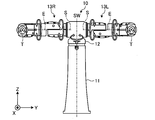
- FIG. 2A is a schematic front view showing the configuration of the robot 10
- FIG. 2B is a schematic top view showing the configuration of the robot 10.
- the robot 10 is a double-armed multi-axis robot. Specifically, the robot 10 includes a base part 11, a body part 12, a left arm part 13L, and a right arm part 13R.
- the base portion 11 is fixed to the floor surface or the like inside the cell 2 (see FIG. 1), and supports the trunk portion 12 so that it can turn around the axis SW at the distal end (see the double arrow around the axis SW). ).
- the trunk portion 12 is supported at the base end portion by the base portion 11, and supports the base end portion of the right arm portion 13R at the right shoulder so that the base end portion can be rotated around the axis S.
- the base end portion of the left arm portion 13L is supported at the left shoulder so as to be rotatable about the axis S (see both arrows around the axis S).
- Each of the left arm portion 13L and the right arm portion 13R includes a plurality of links and joint portions, and can rotate around the axes S, E, and T at each joint portion from the base end portion to the distal end portion. (See double arrows around the axis S, the axis E, and the axis T).
- the left arm portion 13L and the right arm portion 13R can rotate about the axis L, the axis U, the axis R, and the axis B, respectively (the axis L, the axis U, the axis R, and the axis R). (See double arrow around axis B). That is, the robot 10 has 7 axes per arm.
- the robot 10 performs various multi-axis operations combining the two 7-axis arms and the rotation around the axis SW based on the operation instruction from the control device 110.
- the operation instruction from the control device 110 is specifically notified as a drive instruction for each actuator mounted on each joint portion of the robot 10.
- a left hand is attached to the tip of the left arm portion 13L around the axis T
- a right hand is attached to the tip of the right arm portion 13R around the axis T.
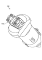
- FIG. 3A is a schematic perspective view illustrating the configuration of the left hand 15L.
- 3B is a schematic front view showing the configuration of the left second gripper 15Lb
- FIG. 3C is a schematic side view showing the configuration of the left second gripper 15Lb.
- the left hand 15L includes a left first gripper 15La, a left second gripper 15Lb, and a sensor unit 15Lc.
- the left first gripper 15La has two gripping claws each having a U-shaped tip, and the jig J and the encoder are gripped by the gripping claws.
- the left second gripper 15Lb has two gripping claws, and grips a connector hook, which will be described later, with the gripping claws.
- the left second gripper 15Lb has a gripping surface 151 and a gripping pin 152 that engage with the connector hook.
- two gripping surfaces 151 are provided for each gripping claw of the left second gripper 15Lb, and the two gripping surfaces 151 are in contact with each other. That is, the grip claw of the left second gripper 15Lb is formed in a substantially blade shape.
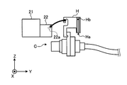
- FIG. 4A is a schematic top view illustrating the configuration of the connector unit 20
- FIG. 4B is a schematic side view illustrating the configuration of the connector unit 20.
- the connector unit 20 includes a base portion 21 and a plurality of (here, four) suspension portions 22.
- Each of the suspension portions 22 has a suspension shaft 22a, and a connector hook H is suspended on the suspension shaft 22a.
- the connector C is connected to the connector hook H, and the second left gripper 15Lb grips and moves the connector hook H to move the connector C to the motor M and the encoder. It moves back and forth between the connector units 20 (see double arrows in the figure).
- the connector hook H is provided with an engagement groove Ha and an engagement hole Hb.
- the engaging groove Ha is formed with a gradient that descends from the side portion to the bottom portion, and the gripping claw of the left second gripper 15Lb formed in the substantially blade shape is engaged with the engaging groove Ha. .
- the gripping claw of the left second gripper 15Lb can be guided into the engagement groove Ha and gripped.
- the engagement hole Hb engages with the grip pin 152 described above, but the peripheral edge of the engagement hole Hb may be chamfered in order to obtain the same effect as the engagement groove Ha.
- FIG. 4A shows an example in which four suspension portions 22 are provided, different types of connectors C are suspended on the four suspension portions 22.
- the motor M usually has a different connector port for receiving the connector C due to mechanical differences such as the presence or absence of a brake. Therefore, by suspending different types of connectors C on the suspension 22, even when different types of motors M are assembled, it is possible to respond appropriately.
- FIG. 5 is a schematic perspective view showing the configuration of the right hand 15R.
- the right hand 15R includes a gripper 15Ra.
- the gripper 15Ra has two gripping claws, and grips the first part and the second part described above with the gripping claws. Further, in order to adjust the direction of a third part (described later) attached in advance to the encoder side, the third part may be gripped. In addition, as described above, the first tool T1 and the second tool T2 may be gripped.
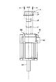
- FIG. 6 is a diagram showing an outline of the procedure for attaching the encoder e.
- the motor M includes a shaft M1 and a bracket M2 on the non-load side.
- the axis AXZ is an axis passing through the axis of the shaft M1.
- the first part p1 is attached to the end (not shown) of the shaft M1 on the side opposite to the load (see the broken arrow extending downward from the first part p1 in the figure). .
- the second part p2 is attached to the attached first part p1 (see the dashed arrow extending downward from the second part p2 in the figure).
- the third part p3 which is an Oldham hub attached in advance to the encoder e, is attached to the attached second part p2 (see the dashed arrow extending downward from the third part p3 in the figure).
- the encoder e is fixed to the bracket M2 using the screw sc (see the broken arrow extending downward from the screw sc in the figure).
- a connector C corresponding to the type of the motor M selected by the robot 10 is connected to the connector port M3 of the motor M during the mounting procedure. Further, when the encoder e is temporarily placed on the bracket M2, a connector C corresponding to the type of the encoder e selected by the robot 10 is connected to the connector port e1 of the encoder e.
- both the connector C connected to the connector port M3 and the connector port e1 are extracted by the robot 10. Thereby, the attachment procedure of the encoder e for one motor M is completed.
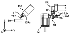
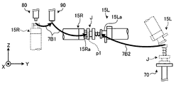
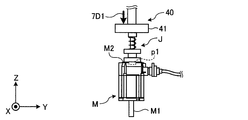
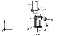
- FIGS. 7A to 7N are explanatory views for explaining the attachment procedure of the encoder e.
- the connector “C1” corresponding to the motor M is denoted by “C1”
- the connector “C2” corresponding to the encoder e is denoted by “C2”.
- the robot 10 grasps the connector hook H to which the connector C1 is connected by the left second gripper 15Lb of the left hand 15L, removes it from the connector unit 20, and removes the removed connector C1 from the motor M. (See arrow 7A1 in the figure).
- DC power is supplied to the motor M, and the motor M is “exposed” and is in an “excited lock” state.
- the illustration of the connector hook H may be omitted for convenience.
- the robot 10 takes out the first part p1 from the first part supply unit 50 with the gripper 15Ra of the right hand 15R (see arrow 7A2 in the figure).
- the robot 10 conveys the first part p1 taken out by the gripper 15Ra of the right hand 15R to the grease application unit 80, and applies grease to a predetermined part of the first part p1. Thereafter, the first part p1 is transported to the imaging region of the camera unit 90, and the grease application state is inspected by the imaging data, and then the right hand 15R is directed toward the left hand 15L (see arrow 7B1 in the figure).
- the robot 10 grips and removes the jig J from the jig unit 70 with the first left gripper 15La of the left hand 15L, and points the left hand 15L in the direction of the right hand 15R (see arrow 7B2 in the figure). .
- the first part p1 gripped by the gripper 15Ra is attached to the bottom surface of the jig J gripped by the left first gripper 15La.
- the robot 10 places the jig J on the non-load side bracket M ⁇ b> 2 of the motor M with the left hand 15 ⁇ / b> L.
- the motor M is slid to the main part of the parts press-fitting unit 40 by the motor moving mechanism 30 here.
- the jig J is pressed vertically downward by the press-fitting portion 41 provided in the parts press-fitting unit 40 (see the arrow 7D1 in the figure), and the first part is passed through the jig J.
- p1 is press-fitted into the end of the shaft M1 exposed inside the bracket M2.
- the motor M is slid forward of the robot 10 by the motor moving mechanism 30.
- the jig J is removed from the motor M that has been slid forward of the robot 10 by the left hand 15L and re-contained in the jig unit 70.
- the sensor unit 15Lc is a non-contact sensor and performs such inspection by irradiating light op, but a contact sensor including a probe or the like may be used.
- the gripper 15Ra of the right hand 15R grips the first tool T1.
- the first tool T1 is a handling tool for measuring rotational torque, and confirms whether or not the shaft M1 after the first part p1 is attached has normal rotational torque.
- the robot 10 takes out the second part p2 from the second part supply unit 60 by the gripper 15Ra of the right hand 15R.
- the robot 10 conveys the second part p2 taken out by the gripper 15Ra of the right hand 15R to the grease application unit 80, and applies the grease to a predetermined part of the second part p2. Thereafter, the second part p2 is transported to the imaging area of the camera unit 90, and the application state of the grease is inspected by the imaging data, and then the second part p2 is attached to the first part p1 (see arrow 7G1 in the drawing). .
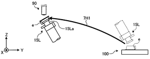
- the robot 10 grips and removes the encoder e from the encoder stocker 100 by the left first gripper 15La of the left hand 15L, and conveys the encoder e to the imaging area of the camera unit 90 ( (See arrow 7H1 in the figure).
- the state of a member (such as the third part p3 or the O-ring described above) attached in advance to the encoder e is inspected.
- the robot 10 faces the left hand 15L and the right hand 15R.
- the direction around the axis T of the third part p3 in the encoder e is adjusted while gripping the third part p3 by the gripper 15Ra (in the drawing). (See double arrow).
- the robot 10 conveys the encoder e to the grease application unit 80 by the left hand 15L, and applies grease to a predetermined part (the above-described third part p3) of the encoder e. Thereafter, the encoder e is transported to the imaging region of the camera unit 90, and the grease application state is inspected by the imaging data, and then the encoder e is temporarily placed on the motor M (see arrow 7J1 in the figure).
- the robot 10 removes the connector C2 from the connector unit 20 and connects the removed connector C2 to the encoder e with the second left gripper 15Lb of the left hand 15L (see arrow 7K1 in the figure). ). And the control apparatus 110 acquires the information regarding the encoder e via this connector C2.
- the information includes, for example, an identifier of the model of the encoder e, and the control device 110 determines whether or not the temporarily placed encoder e is legitimate when attached to the motor M based on the identifier.
- the information includes the origin of the encoder e, and the control device 110 performs an operation of adjusting the encoder e in the direction around the shaft M1 so that the origin of the encoder e matches the origin of the motor M. To instruct.
- the direction of the encoder e is adjusted around the axis T by the left hand 15L.
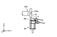
- the gripper 15Ra of the right hand 15R grips the second tool T2.
- the second tool T2 is a handling tool for torque tightening. That is, using the second tool T2, the encoder e is screwed to the bracket M2 with the screw sc (see FIG. 6).
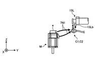
- the robot 10 removes the connector C1 from the motor M and the connector C2 from the encoder e by the second left gripper 15Lb of the left hand 15L (see arrow 7N1 in the figure). ).
- the procedure for attaching the encoder e to one motor M is completed.
- the robot system includes a robot and a control device.
- the robot performs a multi-axis operation based on the operation instruction of the control device.
- the control device attaches a predetermined member to the semi-finished product while controlling the movable portion by supplying power to the semi-finished product having a movable portion that can be controlled by receiving power supply. Instruct.
- a product having a movable portion can be assembled with high accuracy.
- the semi-finished product and the product after assembly is a motor and the movable part is a shaft has been described as an example. Any semi-finished product or product having a movable part that can be controlled may be used.
- the unit configured as a separate unit in the above-described embodiment may be configured as a single unit.
- the first part supply unit and the second part supply unit may be configured as one intermediate member supply unit.
- one unit may be divided into a plurality of units depending on functions.
- the control device may be divided into a power supply control device dedicated to control related to power supply, a robot control device dedicated to control related to a robot, and the like.
- the left hand and the right hand shown in the above-described embodiment are not necessarily associated with the left arm part and the right arm part, respectively. That is, according to the layout configuration in the cell, for example, the right hand may be attached to the left arm portion and the left hand may be attached to the right arm portion.
- the dual-arm robot is exemplified, but the present invention is not limited to this.
- a multi-arm robot having three or more arms may be used.
- a multi-axis robot having seven axes per arm is illustrated, but the number of axes is not limited.
Landscapes
- Engineering & Computer Science (AREA)
- Robotics (AREA)
- Mechanical Engineering (AREA)
- Manipulator (AREA)
- Automatic Assembly (AREA)
Description
2 セル
10 ロボット
11 基台部
12 胴部
13L 左アーム部
13R 右アーム部
15L 左ハンド
15La 左第1グリッパ
15Lb 左第2グリッパ
15Lc センサ部
15R 右ハンド
15Ra グリッパ
20 コネクタユニット
21 基部
22 懸架部
22a 懸架軸
30 モータ移動機構
40 パーツ圧入ユニット
41 圧入部
50 第1パーツ供給ユニット
60 第2パーツ供給ユニット
70 治具ユニット
80 グリス塗布ユニット
90 カメラ部
100 エンコーダストッカ
110 制御装置
151 把持面
152 把持ピン
C コネクタ
C1 コネクタ
C2 コネクタ
H コネクタフック
Ha 係合溝
Hb 係合孔
J 治具
M モータ
M1 シャフト
M2 ブラケット
M3 コネクタ口
T1 第1工具
T2 第2工具
e エンコーダ
e1 コネクタ口
p1 第1パーツ
p2 第2パーツ
p3 第3パーツ
Claims (6)
- ロボットと、
電源の供給を受けることで制御可能となる可動部を具備した半製品へ電源を供給することによって該可動部を制御しながら前記半製品に対して所定の部材を取り付ける動作を前記ロボットへ指示する制御装置と
を備えることを特徴とするロボットシステム。 - 前記半製品は、モータであり、
前記所定の部材は、位置検出器であって、
前記制御装置は、
前記モータに対してコネクタを前記ロボットへ接続させた後、該コネクタを介して電源を供給することによって該モータの回転基準位置である原点を規定し、規定された原点と前記位置検出器の原点とが合致するように該位置検出器を取り付ける動作を前記ロボットへ指示すること
を特徴とする請求項1に記載のロボットシステム。 - 前記制御装置は、
前記モータの種別に応じた前記コネクタを選択する動作を前記ロボットへ指示すること
を特徴とする請求項2に記載のロボットシステム。 - 前記可動部は、
前記モータのシャフトであって、
前記制御装置は、
前記モータに対して前記位置検出器を前記ロボットへ仮置きさせた後、該位置検出器に対してコネクタを前記ロボットへ接続させ、該コネクタを介して取得した前記位置検出器の原点が前記モータの原点と合致するように該位置検出器を前記シャフトまわりの向きに調整する動作を前記ロボットへ指示すること
を特徴とする請求項2または3に記載のロボットシステム。 - 前記制御装置は、
前記位置検出器の取り付け前に前記シャフトへ装着された中間部材の装着状態を、該シャフトを回転させながら前記ロボットへ検査させること
を特徴とする請求項4に記載のロボットシステム。 - 所定の撮像領域を有するカメラ部
をさらに備え、
前記制御装置は、
前記ロボットが前記位置検出器または前記中間部材を保持している場合に、前記撮像領域へ該位置検出器または該中間部材を搬送させ、前記カメラ部に撮像させた撮像データに基づいて該位置検出器および該中間部材の状態を検査すること
を特徴とする請求項5に記載のロボットシステム。
Priority Applications (5)
| Application Number | Priority Date | Filing Date | Title |
|---|---|---|---|
| EP12870063.0A EP2821178A4 (en) | 2012-02-27 | 2012-02-27 | ROBOTIC SYSTEM |
| JP2014501850A JP5910724B2 (ja) | 2012-02-27 | 2012-02-27 | ロボットシステム |
| PCT/JP2012/054759 WO2013128542A1 (ja) | 2012-02-27 | 2012-02-27 | ロボットシステム |
| CN201280069047.2A CN104093522A (zh) | 2012-02-27 | 2012-02-27 | 机器人系统 |
| US14/452,460 US20140350707A1 (en) | 2012-02-27 | 2014-08-05 | Robot system |
Applications Claiming Priority (1)
| Application Number | Priority Date | Filing Date | Title |
|---|---|---|---|
| PCT/JP2012/054759 WO2013128542A1 (ja) | 2012-02-27 | 2012-02-27 | ロボットシステム |
Related Child Applications (1)
| Application Number | Title | Priority Date | Filing Date |
|---|---|---|---|
| US14/452,460 Continuation US20140350707A1 (en) | 2012-02-27 | 2014-08-05 | Robot system |
Publications (1)
| Publication Number | Publication Date |
|---|---|
| WO2013128542A1 true WO2013128542A1 (ja) | 2013-09-06 |
Family
ID=49081801
Family Applications (1)
| Application Number | Title | Priority Date | Filing Date |
|---|---|---|---|
| PCT/JP2012/054759 Ceased WO2013128542A1 (ja) | 2012-02-27 | 2012-02-27 | ロボットシステム |
Country Status (5)
| Country | Link |
|---|---|
| US (1) | US20140350707A1 (ja) |
| EP (1) | EP2821178A4 (ja) |
| JP (1) | JP5910724B2 (ja) |
| CN (1) | CN104093522A (ja) |
| WO (1) | WO2013128542A1 (ja) |
Cited By (1)
| Publication number | Priority date | Publication date | Assignee | Title |
|---|---|---|---|---|
| JP2015085435A (ja) * | 2013-10-30 | 2015-05-07 | Thk株式会社 | 作業装置 |
Families Citing this family (16)
| Publication number | Priority date | Publication date | Assignee | Title |
|---|---|---|---|---|
| JPH0699512B2 (ja) | 1985-07-25 | 1994-12-07 | 三井石油化学工業株式会社 | オレフインの連続重合法 |
| JPH078890B2 (ja) | 1985-07-25 | 1995-02-01 | 三井石油化学工業株式会社 | オレフインの連続重合法 |
| JPH0699510B2 (ja) | 1985-07-25 | 1994-12-07 | 三井石油化学工業株式会社 | オレフインの連続重合法 |
| JPH0699511B2 (ja) | 1985-07-25 | 1994-12-07 | 三井石油化学工業株式会社 | オレフインの連続重合法 |
| JPH078891B2 (ja) | 1985-07-25 | 1995-02-01 | 三井石油化学工業株式会社 | オレフインの連続重合法 |
| FR3021891A1 (fr) * | 2014-06-05 | 2015-12-11 | Aldebaran Robotics | Dispositif de prepositionnement et de fixation amovible de membres articules d'un robot humanoide |
| CN104760043A (zh) * | 2015-02-13 | 2015-07-08 | 上海源致信息技术有限公司 | 一种基于智能避障系统的双臂机器人控制器 |
| CN106393119B (zh) * | 2016-11-25 | 2019-01-11 | 武汉华星光电技术有限公司 | 一种机器人双手臂的控制系统及其方法 |
| JP6831693B2 (ja) * | 2016-12-22 | 2021-02-17 | 川崎重工業株式会社 | 搬送システム及びその運転方法 |
| CN106847489B (zh) * | 2017-01-21 | 2018-02-06 | 温州微特电子有限公司 | 一种变压器装配用高精度定位送料机构 |
| CN110325330A (zh) * | 2017-02-22 | 2019-10-11 | 川崎重工业株式会社 | 用于烹调食品的装置 |
| CN109866203B (zh) * | 2017-12-01 | 2021-05-25 | 中国科学院沈阳自动化研究所 | 一种协作型双臂工业机器人 |
| CN109262218B (zh) * | 2018-10-12 | 2024-05-03 | 高精精密塑胶制品(深圳)有限公司 | 万向螺丝智能组装机 |
| JP2022059167A (ja) * | 2020-10-01 | 2022-04-13 | 株式会社日立製作所 | 移動式ロボット、移動式ロボットシステム及び移動式ロボットの充電池の交換方法 |
| CN113146590A (zh) * | 2021-05-21 | 2021-07-23 | 莱茵科斯特智能科技(青岛)有限公司 | 一种用于安装产品附件的工作站及用于安装附件的机械手 |
| USD1104094S1 (en) * | 2024-02-07 | 2025-12-02 | Hyosung TNS Inc. | Robot cafe booth |
Citations (3)
| Publication number | Priority date | Publication date | Assignee | Title |
|---|---|---|---|---|
| JP2002187030A (ja) * | 2000-12-19 | 2002-07-02 | Asmo Co Ltd | 回転電機の製造方法 |
| JP2003340657A (ja) | 2002-05-28 | 2003-12-02 | Matsushita Electric Works Ltd | 箱体の組み立て方法 |
| JP2009291039A (ja) * | 2008-05-30 | 2009-12-10 | Canon Inc | 電磁駆動装置及び製造方法 |
Family Cites Families (13)
| Publication number | Priority date | Publication date | Assignee | Title |
|---|---|---|---|---|
| US5608847A (en) * | 1981-05-11 | 1997-03-04 | Sensor Adaptive Machines, Inc. | Vision target based assembly |
| US5125298A (en) * | 1983-11-14 | 1992-06-30 | Smith Chalmers O | Automatic wheel assembly mounting system |
| US5237468A (en) * | 1991-10-15 | 1993-08-17 | International Business Machines Corporation | Camera and gripper assembly for an automated storage library |
| JPH08197356A (ja) * | 1995-01-23 | 1996-08-06 | Canon Inc | 組立・加工方法 |
| US6886231B2 (en) * | 1999-06-25 | 2005-05-03 | Burke E. Porter Machinery Company | Robotic apparatus and method for mounting a valve stem on a wheel rim |
| JP3876234B2 (ja) * | 2003-06-17 | 2007-01-31 | ファナック株式会社 | コネクタ把持装置、同装置を備えたコネクタ検査システム及びコネクタ接続システム |
| CN1634726A (zh) * | 2003-12-26 | 2005-07-06 | 郑贯天 | 一种车辆和机器人平面或曲面或台阶供电方法和装置 |
| JP3861889B2 (ja) * | 2004-06-23 | 2006-12-27 | 松下電器産業株式会社 | アーク溶接ロボット |
| CN101002989A (zh) * | 2007-01-30 | 2007-07-25 | 樊明延 | 基于usb接口的可编程机器人玩具及其控制方法 |
| US7798316B2 (en) * | 2007-04-11 | 2010-09-21 | Chrysler Group Llc | Robotic frame handling system |
| JP5105169B2 (ja) * | 2008-01-11 | 2012-12-19 | 日本電産株式会社 | レゾルバ、モータ、パワーステアリング装置およびレゾルバの製造方法 |
| JP4837113B2 (ja) * | 2010-03-18 | 2011-12-14 | ファナック株式会社 | ロボットを用いた嵌合装置 |
| US9188973B2 (en) * | 2011-07-08 | 2015-11-17 | Restoration Robotics, Inc. | Calibration and transformation of a camera system's coordinate system |
-
2012
- 2012-02-27 EP EP12870063.0A patent/EP2821178A4/en not_active Withdrawn
- 2012-02-27 JP JP2014501850A patent/JP5910724B2/ja active Active
- 2012-02-27 WO PCT/JP2012/054759 patent/WO2013128542A1/ja not_active Ceased
- 2012-02-27 CN CN201280069047.2A patent/CN104093522A/zh active Pending
-
2014
- 2014-08-05 US US14/452,460 patent/US20140350707A1/en not_active Abandoned
Patent Citations (3)
| Publication number | Priority date | Publication date | Assignee | Title |
|---|---|---|---|---|
| JP2002187030A (ja) * | 2000-12-19 | 2002-07-02 | Asmo Co Ltd | 回転電機の製造方法 |
| JP2003340657A (ja) | 2002-05-28 | 2003-12-02 | Matsushita Electric Works Ltd | 箱体の組み立て方法 |
| JP2009291039A (ja) * | 2008-05-30 | 2009-12-10 | Canon Inc | 電磁駆動装置及び製造方法 |
Non-Patent Citations (1)
| Title |
|---|
| See also references of EP2821178A4 |
Cited By (1)
| Publication number | Priority date | Publication date | Assignee | Title |
|---|---|---|---|---|
| JP2015085435A (ja) * | 2013-10-30 | 2015-05-07 | Thk株式会社 | 作業装置 |
Also Published As
| Publication number | Publication date |
|---|---|
| US20140350707A1 (en) | 2014-11-27 |
| EP2821178A1 (en) | 2015-01-07 |
| JPWO2013128542A1 (ja) | 2015-07-30 |
| EP2821178A4 (en) | 2016-01-13 |
| JP5910724B2 (ja) | 2016-04-27 |
| CN104093522A (zh) | 2014-10-08 |
Similar Documents
| Publication | Publication Date | Title |
|---|---|---|
| JP5910724B2 (ja) | ロボットシステム | |
| JP6039187B2 (ja) | 組立装置、把持ハンドおよび物品の組立方法 | |
| US10906193B2 (en) | Manufacturing system, method of constructing the manufacturing system, end effector, robot, and working method of robot | |
| US20200021780A1 (en) | Vision unit | |
| CN106863266B (zh) | 机器人、控制装置以及机器人系统 | |
| US9227327B2 (en) | Robot system and method for operating robot system | |
| US11623355B2 (en) | Method for producing a robot and device for carrying out said method | |
| CN102729253A (zh) | 机器人系统和被加工对象物的制造方法 | |
| JP2018083284A (ja) | ロボット制御装置、ロボット、ロボットシステム、及び、ロボット制御方法 | |
| JP5910725B2 (ja) | ロボットシステム | |
| JP6252597B2 (ja) | ロボットシステム | |
| CN113021017B (zh) | 随形自适应3d检测与加工系统 | |
| CN104044131A (zh) | 机器人系统、校正方法及被加工物制造方法 | |
| CN109955279B (zh) | 机器人手、其控制方法、物品的组装方法及存储介质 | |
| CN109996653A (zh) | 作业位置校正方法及作业机器人 | |
| JP2010105105A (ja) | 自動生産装置 | |
| CN107053252A (zh) | 机器人 | |
| JP2005011580A (ja) | コネクタ把持装置、同装置を備えたコネクタ検査システム及びコネクタ接続システム | |
| JP6299769B2 (ja) | ロボットシステム | |
| JP7358747B2 (ja) | ロボットシステム | |
| US11498218B2 (en) | Robot | |
| Cheng et al. | Efficient hand eye calibration method for a Delta robot pick-and-place system | |
| JP2015096290A (ja) | ロボット、ロボットシステム、ロボット制御装置及び方法 | |
| RU118579U1 (ru) | Захватное устройство | |
| JP2017087307A (ja) | ロボットおよびロボットシステム |
Legal Events
| Date | Code | Title | Description |
|---|---|---|---|
| 121 | Ep: the epo has been informed by wipo that ep was designated in this application |
Ref document number: 12870063 Country of ref document: EP Kind code of ref document: A1 |
|
| ENP | Entry into the national phase |
Ref document number: 2014501850 Country of ref document: JP Kind code of ref document: A |
|
| REEP | Request for entry into the european phase |
Ref document number: 2012870063 Country of ref document: EP |
|
| WWE | Wipo information: entry into national phase |
Ref document number: 2012870063 Country of ref document: EP |
|
| NENP | Non-entry into the national phase |
Ref country code: DE |