WO2013128561A1 - Instrument de manipulation de cellules - Google Patents
Instrument de manipulation de cellules Download PDFInfo
- Publication number
- WO2013128561A1 WO2013128561A1 PCT/JP2012/054900 JP2012054900W WO2013128561A1 WO 2013128561 A1 WO2013128561 A1 WO 2013128561A1 JP 2012054900 W JP2012054900 W JP 2012054900W WO 2013128561 A1 WO2013128561 A1 WO 2013128561A1
- Authority
- WO
- WIPO (PCT)
- Prior art keywords
- flow path
- cell handling
- handling tool
- main body
- container
- Prior art date
- Legal status (The legal status is an assumption and is not a legal conclusion. Google has not performed a legal analysis and makes no representation as to the accuracy of the status listed.)
- Ceased
Links
Images


Classifications
-
- C—CHEMISTRY; METALLURGY
- C12—BIOCHEMISTRY; BEER; SPIRITS; WINE; VINEGAR; MICROBIOLOGY; ENZYMOLOGY; MUTATION OR GENETIC ENGINEERING
- C12M—APPARATUS FOR ENZYMOLOGY OR MICROBIOLOGY; APPARATUS FOR CULTURING MICROORGANISMS FOR PRODUCING BIOMASS, FOR GROWING CELLS OR FOR OBTAINING FERMENTATION OR METABOLIC PRODUCTS, i.e. BIOREACTORS OR FERMENTERS
- C12M23/00—Constructional details, e.g. recesses, hinges
- C12M23/02—Form or structure of the vessel
- C12M23/12—Well or multiwell plates
-
- C—CHEMISTRY; METALLURGY
- C12—BIOCHEMISTRY; BEER; SPIRITS; WINE; VINEGAR; MICROBIOLOGY; ENZYMOLOGY; MUTATION OR GENETIC ENGINEERING
- C12M—APPARATUS FOR ENZYMOLOGY OR MICROBIOLOGY; APPARATUS FOR CULTURING MICROORGANISMS FOR PRODUCING BIOMASS, FOR GROWING CELLS OR FOR OBTAINING FERMENTATION OR METABOLIC PRODUCTS, i.e. BIOREACTORS OR FERMENTERS
- C12M33/00—Means for introduction, transport, positioning, extraction, harvesting, peeling or sampling of biological material in or from the apparatus
Definitions
- the present invention relates to a cell handling tool.
- the present invention has been made in order to solve the above-mentioned problems, and its main purpose is to easily prevent the contamination of bacteria while improving the handleability by preventing problems such as accidental sample spillage. Is to be able to do that.
- the cell handling tool of the present invention contains cells, and includes a container body having a flat bottom, and an elastic arm part extending outward from the outer peripheral surface of the container body.
- the container body is housed in a cylindrical container having a bottom represented by a general-purpose petri dish, and a part of the arm part is brought into contact with the inner peripheral surface of the cylindrical container.
- the importance of individual sample management is very high and is preferably used.
- the fixing method is simple and the risk of contamination is low as compared with the case of using a tape or an adhesive sheet.
- the cylindrical container is covered, it is possible to easily prevent the bacteria from being mixed into the housing main body. Furthermore, since the handleability can be improved without changing the size of the container main body (without making it larger than a certain size), it is possible to reduce raw material costs and disposal burden.
- the arm portion is formed in an outwardly convex arc shape. According to such a structure, an arm part can be made to follow the internal peripheral surface of a cylindrical container. Therefore, it can fix more reliably.
- the arm portion is provided away from the bottom surface of the housing main body.
- the inner bottom surface of the cylindrical container may have a step along the outer periphery due to manufacturing reasons. However, according to such a configuration, the arm portion does not hit the step on the inner bottom surface. Can be fixed to.
- a part of the arm portion is brought into contact with an inner peripheral surface of a cylindrical container having a bottom, and the housing main body is fixed to the cylindrical container.
- the cell handling tool of the present invention is used as a sperm separation tool.
- the container main body is discharged from the first flow path for flowing the semen sample, the first supply section for supplying the semen sample to the first flow path, and the first flow path.
- a second storage part for storing the fluid to be discharged, and the middle part of the second flow path is a merged flow path with the first flow path.
- the present invention is suitably applied to such an open cell handling tool.
- the housing portion main body by providing an elastic arm portion on the outer peripheral surface of the housing portion main body, the housing portion main body can be fixed to a cylindrical container having a bottom such as a petri dish, and handling properties are greatly improved. It can be managed as an integrated object with a cylindrical container (storage container). In addition, if the cylindrical container is covered, it is possible to easily prevent the bacteria from being mixed into the housing main body.
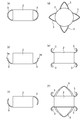
- FIG. 1 It is a schematic perspective view which shows one Example of the cell handling tool of this invention. It is the figure which looked at the use condition of the cell handling tool of FIG. 1 from the top. It is a longitudinal cross-sectional view of the use condition (state which covered the storage container) of the cell handling tool of FIG. (A)-(f) is the schematic which shows the shape of the arm part in another embodiment.
- FIG. 1 to 3 are schematic views showing an embodiment of the cell handling device of the present invention
- FIG. 1 is a perspective view
- FIG. 2 is a view of the usage state from above
- FIG. It is a longitudinal cross-sectional view of a state.
- the cell handling tool 1 includes a storage unit main body 2 that stores cells, and arm portions 3, 3, 3, and 3 that extend outward from the outer peripheral surface of the storage unit main body 2, and separate sperm. Used as a tool.
- the accommodating portion main body 2 is formed in a substantially rectangular flat plate shape, and includes a fine first flow path 21 for flowing a fluid in the main surface direction and a fine second flow path 22.
- the housing main body 2 is formed by stacking and bonding a flat bottom plate 11 and an upper plate 12, and the first flow path 21 and the second flow path 22 are formed on the top surface of the bottom plate 11. It is formed by forming a groove in. While the first flow path 21 is linear, the second flow path 22 joins the first flow path from the right side with respect to the flow direction, and the midstream portion 22b is connected to the first flow path 21. And the downstream portion 22c is branched to the right side.
- the channel diameter of each channel is typically 10 to 1000 ⁇ m, preferably 50 to 400 ⁇ m.
- the housing part 2 is provided with a first supply part 31 for supplying fluid to the first flow path 21 and a second supply part 32 for supplying fluid to the second flow path 22.
- a first supply part 31 for supplying fluid to the first flow path 21
- a second supply part 32 for supplying fluid to the second flow path 22.
- Each supply part 31 and 32 is provided in the part corresponding to the starting end part of each flow path 21 and 22 of upper board 12, circular through-hole 13 formed in the thickness direction, and the upper surface of upper board 12, It is comprised by the cylinder part 14 connected with the through-hole 13.
- the starting ends of the flow paths 21 and 22 are provided in the vicinity of the center of the through holes 13 and 13.
- the inner diameter of the cylindrical portion 14 is substantially the same as the diameter of the through hole 13, and the starting end portions of the flow paths 21 and 22 are opened upward.
- the volume of each supply unit is typically 10 to 1000 ⁇ l.
- the storage unit body 2 includes a first storage unit 41 that stores fluid discharged from the first flow path 21, and a second storage unit 42 that stores fluid discharged from the second flow path 22.
- a first storage unit 41 that stores fluid discharged from the first flow path 21, and a second storage unit 42 that stores fluid discharged from the second flow path 22.
- Each storage portion 41, 42 is provided on the upper surface of the upper plate 12 with a circular through hole 15 formed in the thickness direction at a portion corresponding to the end portion of each flow path 21, 22 of the upper plate 12. It is comprised by the cylinder part 16 connected with the through-hole 15.
- the end of each flow path 21, 22 is provided near the center of the through holes 15, 15.
- the inner diameter of the cylindrical portion 16 is substantially the same as the diameter of the through hole 15, and the end portions of the flow paths 21 and 22 are opened upward.
- the volume of each reservoir is typically 10 to 1000 ⁇ l.
- a semen sample containing sperm is supplied to the first flow path 21, a medium is supplied to the second flow path 22, and the semen sample and the medium are brought into contact in a laminar flow state in the merge flow path 23.
- motile sperm highly motile sperm contained in the semen sample
- the semen sample from which the motile sperm has been separated is discharged to the first reservoir (waste liquid reservoir) 41, and the medium containing the motile sperm is discharged to the second reservoir (motile sperm reservoir) 42.
- Motile sperm and non-motile sperm are separated.
- the separation efficiency can be improved by making the cross-sectional area of the medium flow larger than the cross-sectional area of the semen sample flow.
- one medium flow path for circulating the medium is used, but a plurality of medium flow paths may be formed.
- the four arm portions 3, 3, 3, and 3 are integrally formed on the side surface of the housing portion main body 2 so as to be elastically deformable. How much and in what direction the arm 3 is formed in which position in which position of the housing main body 2 is set as appropriate. In this embodiment, both ends of the opposing side surfaces of the housing main body 2 are arranged.
- the arc-shaped arm portions 3, 3, 3, and 3 that protrude outwardly from the portion extend, and the arm portions 3 and 3 that extend from the same side surface form a single arc shape.
- the arm portion 3 extends from the left and right side surfaces 17 and 18 of the upper plate 12 constituting the housing portion main body 2 in the main surface direction of the upper plate 12, and the arm portion 3 is separated from the bottom surface of the housing portion main body 2. Is formed.
- the arm portion 3 is formed at a height of 1 mm or more and 15 mm or less from the bottom surface of the housing portion main body 2.
- both ends of the arm portion 3 are joined to the housing portion main body 2 to form a substantially semicircular shape or a substantially V shape.
- the arc-shaped arm portions 3 and 3 extending from the same side surface are formed such that their free ends face in opposite directions.
- a bulging portion 3 a bulging outward is formed at the tip of the arc-shaped arm portion 3.
- the arm portion may be a latch member biased outward by a spring or the like.
- the material of the housing part main body 2 and the arm part 3 is not particularly limited, but a thermoplastic resin is preferable from the viewpoint of moldability.
- the thermoplastic resin include polyethylene (PE) such as high density polyethylene (HDPE), medium density polyethylene (MDPE), and low density polyethylene (LDPE), polypropylene (PP), polyvinylidene chloride, and polyvinyl chloride (PVC).
- PE polyethylene
- HDPE high density polyethylene
- MDPE medium density polyethylene
- LDPE low density polyethylene
- PP polypropylene
- PP polyvinylidene chloride
- PVC polyvinyl chloride
- PTFE Polytetrafluoroethylene
- PS polystyrene
- PVAc polyvinyl acetate
- Teflon registered trademark
- ABS resin acrylonitrile butadiene styrene resin
- AS resin acrylonitrile styrene resin
- PMMA etc.
- General purpose plastics such as (meth) acrylic resin, polyethylene terephthalate (PET); polyamide (PA), polyacetal (POM), polycarbonate (PC), modified polyphenylene ether (modified PPE), polybutylene terephthalate (PBT), glass fiber reinforced polyethylene terephthalate (GF-PET), engineering plastics such as cyclic polyolefin (COP); polyphenylene sulfide (PPS), polytetrafluoroethylene (PTFE), polysulfone (PSF), polyether Examples include super engineering plastics such as sulfone (PES), amorphous polyarylate (PAR), liquid crystal polymer (LCP), polyether ether ketone (PEEK), thermoplastic polyimide (PI), and polyamideimide (PAI).
- PES polyethylene terephthalate
- PA polyamide
- POM polyacetal
- PC polycarbonate
- PC modified polyphenylene ether
- PBT polybutylene terephthalate
- FIGS. 2 and 3 are schematic views showing the usage state of the cell handling tool 1 of this embodiment.
- the cell handling tool 1 is placed on a cylindrical container 101 having a bottom typified by a general-purpose petri dish, and is fixed by bringing a part of an arm 3 that can be elastically deformed into contact with the inner peripheral surface of the cylindrical container 101.
- the arm portion 3 is formed away from the bottom surface of the housing portion main body 2, even if the step 101 a is provided along the outer periphery of the inner bottom surface of the cylindrical container 101 as in the illustrated example, the arm portion 3 is not It does not hit the step 101a. In such a fixed state, the cells are separated (selected), cultured, stored, and the like.
- the lid 102 of the cylindrical container 101 If the lid 102 of the cylindrical container 101 is used, it is possible to prevent the bacteria from being mixed into the housing body 2. Moreover, the bad influence (for example, influence by a solvent evaporating) to the cell accommodated in the accommodating part main body 2 can be suppressed.
- the case of using as a sperm separation tool has been described.
- it can be applied as a cell culture tool by providing a medium in the container body.
- the cell handling device of the present invention can be suitably used as a device for separating (selecting), culturing and storing cells.
Landscapes
- Health & Medical Sciences (AREA)
- Life Sciences & Earth Sciences (AREA)
- Organic Chemistry (AREA)
- Engineering & Computer Science (AREA)
- Bioinformatics & Cheminformatics (AREA)
- Chemical & Material Sciences (AREA)
- Zoology (AREA)
- Wood Science & Technology (AREA)
- Sustainable Development (AREA)
- Microbiology (AREA)
- Biotechnology (AREA)
- Biomedical Technology (AREA)
- Biochemistry (AREA)
- General Engineering & Computer Science (AREA)
- General Health & Medical Sciences (AREA)
- Genetics & Genomics (AREA)
- Clinical Laboratory Science (AREA)
- Molecular Biology (AREA)
- Apparatus Associated With Microorganisms And Enzymes (AREA)
Abstract
L'invention concerne un instrument de manipulation de cellules capable d'empêcher la contamination microbienne tout en améliorant les propriétés de manipulation et en prévenant l'apparition de problèmes tels que le déversement accidentel d'un échantillon. Ledit instrument (1) de manipulation de cellules selon l'invention comporte une partie logement (2) qui reçoit des cellules et présente une partie de fond en forme de plateau ainsi qu'une partie formant branches (3) qui est élastique et s'étend entre la surface périphérique extérieure de la partie logement (2) et l'extérieur.
Priority Applications (1)
| Application Number | Priority Date | Filing Date | Title |
|---|---|---|---|
| PCT/JP2012/054900 WO2013128561A1 (fr) | 2012-02-28 | 2012-02-28 | Instrument de manipulation de cellules |
Applications Claiming Priority (1)
| Application Number | Priority Date | Filing Date | Title |
|---|---|---|---|
| PCT/JP2012/054900 WO2013128561A1 (fr) | 2012-02-28 | 2012-02-28 | Instrument de manipulation de cellules |
Publications (1)
| Publication Number | Publication Date |
|---|---|
| WO2013128561A1 true WO2013128561A1 (fr) | 2013-09-06 |
Family
ID=49081815
Family Applications (1)
| Application Number | Title | Priority Date | Filing Date |
|---|---|---|---|
| PCT/JP2012/054900 Ceased WO2013128561A1 (fr) | 2012-02-28 | 2012-02-28 | Instrument de manipulation de cellules |
Country Status (1)
| Country | Link |
|---|---|
| WO (1) | WO2013128561A1 (fr) |
Cited By (1)
| Publication number | Priority date | Publication date | Assignee | Title |
|---|---|---|---|---|
| JP2017531440A (ja) * | 2014-10-20 | 2017-10-26 | ザ ユニバーシティ オブ ユタ リサーチ ファウンデイション | 組織試料処理システム及びそれに関連する方法 |
Citations (3)
| Publication number | Priority date | Publication date | Assignee | Title |
|---|---|---|---|---|
| JP2005518794A (ja) * | 2002-02-27 | 2005-06-30 | ミシガン大学リージェンツ | 低運動性粒子からの運動性粒子選別方法及びそれに用いる装置 |
| JP2007515936A (ja) * | 2003-09-04 | 2007-06-21 | アリックス インコーポレイテッド | レーザ操縦を用いた多層流に基づく粒子及び細胞の分離 |
| JP2012024020A (ja) * | 2010-07-23 | 2012-02-09 | Nippi:Kk | スライドグラス収納用培養容器 |
-
2012
- 2012-02-28 WO PCT/JP2012/054900 patent/WO2013128561A1/fr not_active Ceased
Patent Citations (3)
| Publication number | Priority date | Publication date | Assignee | Title |
|---|---|---|---|---|
| JP2005518794A (ja) * | 2002-02-27 | 2005-06-30 | ミシガン大学リージェンツ | 低運動性粒子からの運動性粒子選別方法及びそれに用いる装置 |
| JP2007515936A (ja) * | 2003-09-04 | 2007-06-21 | アリックス インコーポレイテッド | レーザ操縦を用いた多層流に基づく粒子及び細胞の分離 |
| JP2012024020A (ja) * | 2010-07-23 | 2012-02-09 | Nippi:Kk | スライドグラス収納用培養容器 |
Cited By (1)
| Publication number | Priority date | Publication date | Assignee | Title |
|---|---|---|---|---|
| JP2017531440A (ja) * | 2014-10-20 | 2017-10-26 | ザ ユニバーシティ オブ ユタ リサーチ ファウンデイション | 組織試料処理システム及びそれに関連する方法 |
Similar Documents
| Publication | Publication Date | Title |
|---|---|---|
| JP7387681B2 (ja) | 灌流マニホールドアセンブリ | |
| US7740759B2 (en) | Magnetic separation device | |
| JP6910031B2 (ja) | 細胞・生体組織輸送用容器 | |
| CA2820177A1 (fr) | Cartouche d'analyse de liquide | |
| WO2016208018A1 (fr) | Ensemble pour transport de récipient de culture et unité de transport de cellule/tissu biologique | |
| JP2008128776A (ja) | 蓋付き容器 | |
| US20220105506A1 (en) | Fluid-handling system and cartridge | |
| WO2013128561A1 (fr) | Instrument de manipulation de cellules | |
| WO2015104797A1 (fr) | Dispositif de tri de spermatozoïdes mobiles | |
| JP5658849B1 (ja) | 押し栓構造を備えたストッパー付きチューブ | |
| JP2019113472A (ja) | 秤取構造及びマイクロチップ | |
| US10105478B2 (en) | Analysis cartridge with filter unit | |
| US9557287B2 (en) | Cartridge for processing a fluid | |
| WO2013132897A1 (fr) | Moyen pour manipuler du sperme | |
| JP6446146B2 (ja) | マイクロチップ | |
| US10195417B2 (en) | Connecting element for providing fluidic connection between vessels | |
| NZ715433A (en) | Sealing disk for a closure cap for containers, especially bottles | |
| JP7543710B2 (ja) | マイクロ流体デバイス | |
| JP2020091116A (ja) | 流体取扱システム | |
| JP3192421U (ja) | 培養容器用アダプタ及びこれを備えた培地供給システム | |
| JP2011153990A (ja) | 試薬容器セット及び連結部材 | |
| JP2020008407A (ja) | 検査用具及び検査システム | |
| WO2014128960A1 (fr) | Dispositif microfluidique |
Legal Events
| Date | Code | Title | Description |
|---|---|---|---|
| 121 | Ep: the epo has been informed by wipo that ep was designated in this application |
Ref document number: 12870080 Country of ref document: EP Kind code of ref document: A1 |
|
| NENP | Non-entry into the national phase |
Ref country code: DE |
|
| 122 | Ep: pct application non-entry in european phase |
Ref document number: 12870080 Country of ref document: EP Kind code of ref document: A1 |
|
| NENP | Non-entry into the national phase |
Ref country code: JP |