WO2013128667A1 - Distributeur d'eau - Google Patents
Distributeur d'eau Download PDFInfo
- Publication number
- WO2013128667A1 WO2013128667A1 PCT/JP2012/067323 JP2012067323W WO2013128667A1 WO 2013128667 A1 WO2013128667 A1 WO 2013128667A1 JP 2012067323 W JP2012067323 W JP 2012067323W WO 2013128667 A1 WO2013128667 A1 WO 2013128667A1
- Authority
- WO
- WIPO (PCT)
- Prior art keywords
- water
- pump
- control unit
- storage tank
- water level
- Prior art date
- Legal status (The legal status is an assumption and is not a legal conclusion. Google has not performed a legal analysis and makes no representation as to the accuracy of the status listed.)
- Ceased
Links
Images



Classifications
-
- B—PERFORMING OPERATIONS; TRANSPORTING
- B67—OPENING, CLOSING OR CLEANING BOTTLES, JARS OR SIMILAR CONTAINERS; LIQUID HANDLING
- B67D—DISPENSING, DELIVERING OR TRANSFERRING LIQUIDS, NOT OTHERWISE PROVIDED FOR
- B67D3/00—Apparatus or devices for controlling flow of liquids under gravity from storage containers for dispensing purposes
- B67D3/0003—Apparatus or devices for controlling flow of liquids under gravity from storage containers for dispensing purposes provided with automatic fluid control means
-
- B—PERFORMING OPERATIONS; TRANSPORTING
- B67—OPENING, CLOSING OR CLEANING BOTTLES, JARS OR SIMILAR CONTAINERS; LIQUID HANDLING
- B67D—DISPENSING, DELIVERING OR TRANSFERRING LIQUIDS, NOT OTHERWISE PROVIDED FOR
- B67D1/00—Apparatus or devices for dispensing beverages on draught
- B67D1/0003—Apparatus or devices for dispensing beverages on draught the beverage being a single liquid
- B67D1/0004—Apparatus or devices for dispensing beverages on draught the beverage being a single liquid the beverage being stored in a container, e.g. bottle, cartridge, bag-in-box, bowl
-
- B—PERFORMING OPERATIONS; TRANSPORTING
- B67—OPENING, CLOSING OR CLEANING BOTTLES, JARS OR SIMILAR CONTAINERS; LIQUID HANDLING
- B67D—DISPENSING, DELIVERING OR TRANSFERRING LIQUIDS, NOT OTHERWISE PROVIDED FOR
- B67D1/00—Apparatus or devices for dispensing beverages on draught
- B67D1/0003—Apparatus or devices for dispensing beverages on draught the beverage being a single liquid
- B67D1/0004—Apparatus or devices for dispensing beverages on draught the beverage being a single liquid the beverage being stored in a container, e.g. bottle, cartridge, bag-in-box, bowl
- B67D1/0005—Apparatus or devices for dispensing beverages on draught the beverage being a single liquid the beverage being stored in a container, e.g. bottle, cartridge, bag-in-box, bowl the apparatus comprising means for automatically controlling the amount to be dispensed
- B67D1/0006—Apparatus or devices for dispensing beverages on draught the beverage being a single liquid the beverage being stored in a container, e.g. bottle, cartridge, bag-in-box, bowl the apparatus comprising means for automatically controlling the amount to be dispensed based on the timed opening of a valve
-
- B—PERFORMING OPERATIONS; TRANSPORTING
- B67—OPENING, CLOSING OR CLEANING BOTTLES, JARS OR SIMILAR CONTAINERS; LIQUID HANDLING
- B67D—DISPENSING, DELIVERING OR TRANSFERRING LIQUIDS, NOT OTHERWISE PROVIDED FOR
- B67D1/00—Apparatus or devices for dispensing beverages on draught
- B67D1/04—Apparatus utilising compressed air or other gas acting directly or indirectly on beverages in storage containers
- B67D1/0412—Apparatus utilising compressed air or other gas acting directly or indirectly on beverages in storage containers the whole dispensing unit being fixed to the container
- B67D1/0425—Apparatus utilising compressed air or other gas acting directly or indirectly on beverages in storage containers the whole dispensing unit being fixed to the container comprising an air pump system
- B67D1/0431—Apparatus utilising compressed air or other gas acting directly or indirectly on beverages in storage containers the whole dispensing unit being fixed to the container comprising an air pump system power-operated
-
- B—PERFORMING OPERATIONS; TRANSPORTING
- B67—OPENING, CLOSING OR CLEANING BOTTLES, JARS OR SIMILAR CONTAINERS; LIQUID HANDLING
- B67D—DISPENSING, DELIVERING OR TRANSFERRING LIQUIDS, NOT OTHERWISE PROVIDED FOR
- B67D1/00—Apparatus or devices for dispensing beverages on draught
- B67D1/08—Details
- B67D1/0857—Cooling arrangements
-
- B—PERFORMING OPERATIONS; TRANSPORTING
- B67—OPENING, CLOSING OR CLEANING BOTTLES, JARS OR SIMILAR CONTAINERS; LIQUID HANDLING
- B67D—DISPENSING, DELIVERING OR TRANSFERRING LIQUIDS, NOT OTHERWISE PROVIDED FOR
- B67D1/00—Apparatus or devices for dispensing beverages on draught
- B67D1/08—Details
- B67D1/0871—Level gauges for beverage storage containers
-
- B—PERFORMING OPERATIONS; TRANSPORTING
- B67—OPENING, CLOSING OR CLEANING BOTTLES, JARS OR SIMILAR CONTAINERS; LIQUID HANDLING
- B67D—DISPENSING, DELIVERING OR TRANSFERRING LIQUIDS, NOT OTHERWISE PROVIDED FOR
- B67D1/00—Apparatus or devices for dispensing beverages on draught
- B67D1/08—Details
- B67D1/0888—Means comprising electronic circuitry (e.g. control panels, switching or controlling means)
-
- B—PERFORMING OPERATIONS; TRANSPORTING
- B67—OPENING, CLOSING OR CLEANING BOTTLES, JARS OR SIMILAR CONTAINERS; LIQUID HANDLING
- B67D—DISPENSING, DELIVERING OR TRANSFERRING LIQUIDS, NOT OTHERWISE PROVIDED FOR
- B67D1/00—Apparatus or devices for dispensing beverages on draught
- B67D1/08—Details
- B67D1/0895—Heating arrangements
-
- B—PERFORMING OPERATIONS; TRANSPORTING
- B67—OPENING, CLOSING OR CLEANING BOTTLES, JARS OR SIMILAR CONTAINERS; LIQUID HANDLING
- B67D—DISPENSING, DELIVERING OR TRANSFERRING LIQUIDS, NOT OTHERWISE PROVIDED FOR
- B67D1/00—Apparatus or devices for dispensing beverages on draught
- B67D1/08—Details
- B67D1/0895—Heating arrangements
- B67D1/0897—Heating arrangements located in nozzles
-
- B—PERFORMING OPERATIONS; TRANSPORTING
- B67—OPENING, CLOSING OR CLEANING BOTTLES, JARS OR SIMILAR CONTAINERS; LIQUID HANDLING
- B67D—DISPENSING, DELIVERING OR TRANSFERRING LIQUIDS, NOT OTHERWISE PROVIDED FOR
- B67D1/00—Apparatus or devices for dispensing beverages on draught
- B67D1/08—Details
- B67D1/12—Flow or pressure control devices or systems, e.g. valves, gas pressure control, level control in storage containers
-
- B—PERFORMING OPERATIONS; TRANSPORTING
- B67—OPENING, CLOSING OR CLEANING BOTTLES, JARS OR SIMILAR CONTAINERS; LIQUID HANDLING
- B67D—DISPENSING, DELIVERING OR TRANSFERRING LIQUIDS, NOT OTHERWISE PROVIDED FOR
- B67D1/00—Apparatus or devices for dispensing beverages on draught
- B67D1/08—Details
- B67D1/12—Flow or pressure control devices or systems, e.g. valves, gas pressure control, level control in storage containers
- B67D1/1202—Flow control, e.g. for controlling total amount or mixture ratio of liquids to be dispensed
- B67D1/1234—Flow control, e.g. for controlling total amount or mixture ratio of liquids to be dispensed to determine the total amount
- B67D1/1243—Flow control, e.g. for controlling total amount or mixture ratio of liquids to be dispensed to determine the total amount comprising flow or pressure sensors, e.g. for controlling pumps
-
- B—PERFORMING OPERATIONS; TRANSPORTING
- B67—OPENING, CLOSING OR CLEANING BOTTLES, JARS OR SIMILAR CONTAINERS; LIQUID HANDLING
- B67D—DISPENSING, DELIVERING OR TRANSFERRING LIQUIDS, NOT OTHERWISE PROVIDED FOR
- B67D1/00—Apparatus or devices for dispensing beverages on draught
- B67D1/08—Details
- B67D1/0801—Details of beverage containers, e.g. casks, kegs
- B67D2001/0812—Bottles, cartridges or similar containers
- B67D2001/0814—Bottles, cartridges or similar containers for upside down use
-
- B—PERFORMING OPERATIONS; TRANSPORTING
- B67—OPENING, CLOSING OR CLEANING BOTTLES, JARS OR SIMILAR CONTAINERS; LIQUID HANDLING
- B67D—DISPENSING, DELIVERING OR TRANSFERRING LIQUIDS, NOT OTHERWISE PROVIDED FOR
- B67D1/00—Apparatus or devices for dispensing beverages on draught
- B67D1/08—Details
- B67D1/12—Flow or pressure control devices or systems, e.g. valves, gas pressure control, level control in storage containers
- B67D2001/1259—Fluid level control devices
- B67D2001/1263—Fluid level control devices the level being detected electrically
-
- B—PERFORMING OPERATIONS; TRANSPORTING
- B67—OPENING, CLOSING OR CLEANING BOTTLES, JARS OR SIMILAR CONTAINERS; LIQUID HANDLING
- B67D—DISPENSING, DELIVERING OR TRANSFERRING LIQUIDS, NOT OTHERWISE PROVIDED FOR
- B67D2210/00—Indexing scheme relating to aspects and details of apparatus or devices for dispensing beverages on draught or for controlling flow of liquids under gravity from storage containers for dispensing purposes
- B67D2210/00002—Purifying means
- B67D2210/00013—Sterilising means
- B67D2210/00023—Oxygenators
-
- Y—GENERAL TAGGING OF NEW TECHNOLOGICAL DEVELOPMENTS; GENERAL TAGGING OF CROSS-SECTIONAL TECHNOLOGIES SPANNING OVER SEVERAL SECTIONS OF THE IPC; TECHNICAL SUBJECTS COVERED BY FORMER USPC CROSS-REFERENCE ART COLLECTIONS [XRACs] AND DIGESTS
- Y10—TECHNICAL SUBJECTS COVERED BY FORMER USPC
- Y10T—TECHNICAL SUBJECTS COVERED BY FORMER US CLASSIFICATION
- Y10T137/00—Fluid handling
- Y10T137/8593—Systems
- Y10T137/85978—With pump
- Y10T137/85986—Pumped fluid control
Definitions
- the present invention relates to a water server capable of pouring water previously transferred from a replaceable raw water container to a storage tank as drinking water.
- the water in the storage tank flows out from the water injection channel, and the discharged water can be poured into the user's cup or the like.
- the raw water container is disposed at the lower part of the casing and the storage tank is provided at a higher position than the raw water container.
- the storage tank is higher than the raw water container, a water supply channel that pumps water from the raw water container to the storage tank is employed (Patent Documents 1 and 2).
- Japanese Patent Laid-Open No. 2001-153523 (particularly FIG. 1, paragraph 0012) Japanese Patent No. 4802299
- the water level in the storage tank is monitored by a water level sensor.
- the control unit of the water server starts the pump by the sensor input for detecting the lower limit, and stops the pump by the sensor input for detecting the upper limit.
- the upper limit detection of the storage tank is set to a water level that prevents the storage tank from overflowing, but if the water level sensor cannot detect the upper limit water level for some reason, an overflow may occur.
- the problem to be solved by the present invention is to prevent overflow from the storage tank even if the water level sensor of the water server cannot normally detect the upper limit water level.
- a water supply path for pumping water from an exchangeable raw water container to a storage tank provided in a housing, a water supply path for pouring water from the storage tank, and a storage tank in the storage tank A water level sensor that performs lower limit detection and upper limit detection; and a control unit that controls the pump, wherein the control unit starts the pump by a sensor input of the lower limit detection, and the pump by a sensor input of the upper limit detection
- the control unit measures an elapsed time from the start and stops the pump at a predetermined elapsed time that exceeds the water level of the upper limit detection and overflows from the storage tank. did.
- the time required from when the control unit receives the sensor input of the lower limit detection to start the pump until the water level in the storage tank reaches the upper limit detection level and the time required to overflow from the storage tank are based on pumping performance. It can be determined as an experimental value.
- the fact that the pump operation continues after the time from the start of the pump until the water level reaches the upper limit detection is an abnormal operation time leading to an overflow. Therefore, the water level sensor normally detects the upper limit water level by adopting a control unit that measures the elapsed time from the start of the pump, stops the pump at a predetermined elapsed time before exceeding the upper limit detection water level and overflows from the storage tank. Even if it becomes impossible, overflow from the storage tank can be prevented.
- a float sensor can be adopted as the water level sensor.
- the float sensor is an automatic switch provided to open and close the lower limit detection switch and the upper limit detection switch by a float (floating element) that moves up and down as the water level rises and lowers, and a guide for guiding the float (for example, (Stem, rocking arm) on the tank side.
- a float floating element
- the float sensor may recover its function. In this case, it is inconvenient for the user of the water server if the pump operation is locked without being possible. If the control unit stops the pump, the input state from the water level sensor can be reset to avoid locking in this case.
- the present invention provides a water supply path for pumping the water of the replaceable raw water container to a storage tank provided in the housing, a water supply path for pouring water from the storage tank, and the inside of the storage tank.
- a water level sensor that performs lower limit detection and upper limit detection, and a control unit that controls the pump, wherein the control unit starts the pump by the sensor input of the lower limit detection, and by the sensor input of the upper limit detection
- the control unit measures an elapsed time from the start and stops the pump at a predetermined elapsed time that exceeds the water level of the upper limit detection and overflows from the storage tank.
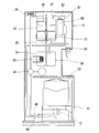
- the water server includes a raw water container 20 disposed in a lower part of the casing 10 and a water supply path 40 that pumps water from the raw water container 20 to a storage tank 30 provided in the casing 10 by a pump 41.
- a soft container having a side wall that can be shrunk at atmospheric pressure as the amount of residual water decreases is employed.
- the housing 10 is composed of a vertically placed machine frame.
- a drawer opening through which the slide base 11 is taken in and out is provided at the lower part of the housing 10.
- the lower part of the housing 10 refers to the lower side of the housing 10 at the ground level.
- the concept of height is used to mean the ground height.
- the slide table 11 is slidable in a horizontal linear direction along a guide rail standing on the bottom plate of the housing 10.
- the slide table 11 has a piercing portion 12 that pushes the stopper of the raw water container 20 placed upside down.
- the piercing portion 12 is internally divided into one end portion of the water supply passage 40 and one end portion of the intake passage 80.
- the illustrated piercing portion 12 is illustrated as a fixed type, a movable piercing portion may be employed as disclosed in Patent Document 2.
- the storage tank 30 is a temporary storage tank that adjusts the temperature of the stored water.
- the illustrated storage tank 30 is divided into a cold water tank 32 that cools the stored water with a heat exchanger 31, a hot water tank 34 that heats the stored water with a heater 33, and a transfer channel 35.
- the transfer channel 35 is passed through a baffle 36 that obstructs the descent of water from the water supply channel 40.
- the water in the raw water container 20 drawn up in the water supply path 40 is sent to the cold water tank 32, and the water in the upper part of the cold water tank 32 flows to the hot water tank 34 via the transfer channel 35.
- the water injection path 50 connected to the storage tank 30 is also composed of two independent systems, a cold water system connected to the cold water tank 32 and a hot water system connected to the hot water tank 34.
- a valve (not shown) that is a boundary between the cold water system or the hot water system of the water injection channel 50 and the storage tank 30 is opened by a user's operation, the cold water layer (shown in the figure) below the baffle 36 of the cold water tank 32 from the cold water system or the hot water system.
- the water in the upper part of the hot water tank 34 flows out, and the discharged water can be poured into a cup or the like.
- the storage tank 30 can be only one of a cold water tank and a hot water tank.
- a pump 41 is incorporated in the middle of the water supply channel 40.
- the pump 41 for example, a plunger pump or a gear pump can be used.
- the other end of the ascending pipe 81 of the intake passage 80 is connected to the air chamber 90.
- the other end portion 82 of the intake passage 80 serves as an air intake port of the air chamber 90 that communicates with the air.
- the intake passage 80 is always open between the raw water container 20 and the atmosphere.
- a sterilization device that mixes sterilizing gas in the air in the intake passage 80 and the air chamber 90 is provided.
- the sterilizer for example, an ozone generator that generates ozone from the atmospheric oxygen taken in can be employed.
- the operation control of the sterilizer is interlocked with the operation of the pump 41.
- An air hole 37 is provided in the storage tank 30.
- the air hole 37 always communicates with the ascending pipe 81 and the air chamber 90 of the intake passage 80.
- the storage tank 30 sucks the atmosphere containing the bactericidal gas from the ascending pipe 81 of the atmospheric pressure and the air chamber 90 through the air hole 37, and the water level in the storage tank 30 increases.
- the air in the storage tank 30 goes out from the air hole 37 to the atmosphere through the air chamber 90.
- the overflow height at which water first overflows from the storage tank 30 is defined as the overflow height H of the water supply path 40 which is the lower of the overflow height of the air hole 37 and the overflow height of the water supply path 40. It has become.
- the water level sensor 60 is a float sensor.
- the control unit 70 includes a sequencer that controls the pump 41 and the like.
- the water level sensor 60 has a float 61 that floats on the water surface of the storage tank 30 and is composed of a level switch that switches on / off of the reed switch in the stem 62 by a magnetic field of a permanent magnet on the float 61 side.
- the water supply path 40 has a second end 42 for discharging water pumped up by the pressurization of the pump 41 at a position higher than the upper limit detection water level WL1 in the cold water tank 32.
- the upper limit detection switch of the water level sensor 60 is switched by the magnetic field of the permanent magnet on the float 61 side at the water level WL1 lower than the overflow height H and lower than the other end 42 of the water supply channel 40.
- the upper limit detection signal generated by this switching is transmitted to the input unit 71 of the control unit 70 shown in FIG.
- the lower limit detection switch of the water level sensor 60 shown in FIG. 3 is similarly switched at the water level WL2 higher than the baffle 36, and the lower limit detection signal generated thereby is transmitted to the input unit 71 of the control unit 70 shown in FIG.
- the input unit 71 of the control unit 70 transmits signals (sensor input) from sensors such as the water level sensor 60 and operation switches to the arithmetic control unit 72.
- the arithmetic control unit 72 executes various programs such as a timer and a counter stored in the program memory.
- the arithmetic control unit 72 writes the sensor input to the input image memory and the generated output data to the output latch memory by program processing.
- the output unit 73 converts the output data written in the output latch memory and the data from the arithmetic control unit 72 into a signal to an external device such as the pump 41.
- the arithmetic control unit 72 starts the pump 41 by the sensor input for detecting the lower limit of the water level sensor 60, stops the pump 41 by the sensor input for detecting the upper limit of the water level sensor 60, and detects the lower limit of the water level sensor 60.
- a program process for measuring the elapsed time from the start of the pump 41 by sensor input and a program process for stopping the pump 41 at a predetermined elapsed time are executed.
- the predetermined elapsed time includes the experimental value of the elapsed time required for pumping up from the water level WL2 to the water level WL1 shown in FIG.
- the time difference from the experimental value of the elapsed time required for the above is not exceeded and the delay time required until the pump 41 loses the pumping capacity from the sensor input of the lower limit detection is advanced so as not to reach the water level H.
- the value is set to. This value is registered in advance as data for condition determination in the program memory of the control unit 70 shown in FIGS.
- the predetermined elapsed time is It can be set to about 20% longer than the experimental value of the elapsed time required for pumping by the pump 41 from WL2 to the water level WL1.
- the arithmetic control unit 72 waits for a signal transmitted from the water level sensor 60 via the input unit 71 and writes the transmitted signal to the input image memory (start). ). Thereafter, the arithmetic control unit 72 starts monitoring whether or not data indicating the lower limit detection of the water level sensor 60 is written in the input image memory (step S1).
- Step S1 When the calculation control unit 72 confirms the writing in (Step S1), the calculation control unit 72 generates ON data of the pump 41, and the output unit 73 transmits an ON signal to the control circuit of the pump 41. In addition, when confirming the writing in (Step S1), the arithmetic control unit 72 starts measuring elapsed time (Step S2). As a result, the control unit 70 starts the pump 41 and starts measuring the elapsed time from the start.
- Step S2 After the execution of (Step S2), the arithmetic control unit 72 starts monitoring whether or not data indicating the upper limit detection of the water level sensor 60 is written in the input image memory (Step S3). Further, the calculation control unit 72 monitors whether or not the elapsed time has reached a predetermined elapsed time after the execution of (Step S2) (Step S4).
- Step S3 When the calculation control unit 72 confirms the writing in (Step S3), the calculation control unit 72 generates OFF data of the pump 41, and the output unit 73 transmits the OFF signal. Thereby, the control unit 70 stops the pump 41. In addition, when confirming the writing in (Step S3), the arithmetic control unit 72 stops measuring the elapsed time and resets the timer (Step S5).
- Step S4 when confirming the arrival of the predetermined elapsed time in (Step S4), the calculation control unit 72 generates OFF data of the pump 41, and the output unit 73 transmits the OFF signal (Step S3). Thereby, the control unit 70 stops the pump 41.
- the pump 41 loses its pumping capacity at a time before the water level WL1 of the upper limit detection of the storage tank 30 is exceeded and before the overflow water level H is reached. Therefore, in this water server, various conditions such as water temperature, tank internal pressure, and water scale adhering to the stem 62 are accidentally overlapped, and the movement of the float 61 becomes temporarily awkward, or the float 61 is fixed to the stem 62. Even if an abnormality occurs and the water level sensor 60 cannot normally detect the upper limit water level, overflow from the storage tank 30 can be prevented.
- Step S4 when confirming the writing in (Step S4), the arithmetic control unit 72 stops measuring the elapsed time and resets the timer (Step S5).
- the arithmetic control unit 72 clears the storage units of the data indicating the lower limit detection and the data indicating the upper limit detection written in the input image memory, and starts (Start). Return (step S6). Thereby, the control part 70 resets the input state from a water level sensor. After (Step S6), when the water in the storage tank 30 is consumed and the water surface, the water temperature, and the tank internal pressure fluctuate, the above-mentioned conditions collapse and the float 61 moves normally with respect to the stem 62. The lower limit of the water level sensor 60 can be detected.
- control unit 70 can write a new lower limit detection sensor input in the input image memory, so that the lock is avoided and the pump 41 is started again by the processes of (Step S1) to (Step S5). A stop can be performed. As long as the movement of the float 61 does not return to normal, the lower limit detection of the water level sensor 60 does not occur, so there is no concern that the pump 41 is started again in an abnormal state where the upper limit detection is not possible.
- Step S1 Since the sterilizer is also operating during the operation of the pump 41, the amount of sterilizing gas in the ascending pipe 81 and the air chamber 90 increases.
- Step S2 the control unit 70 confirmed in (Step S1) performs the processes related to the stop of the pump 41 (Step S2) to (Step S6).
- Step S6 the operation of the sterilizer is stopped and the temperature adjustment function (heat exchanger 31 and heater 33) of the storage tank 30 is started.
- the raw water container 20 performs the spontaneous suction of the atmosphere from the intake passage 80.
- the self-priming of the raw water container 20 balances the inside and outside of the raw water container 20 with the atmospheric pressure even if the volume of the raw water container 20 does not decrease, so that the pump 41 does not forcibly pump up.
- the water server includes a sensor that detects a used-up state, and when the sensor input is transmitted to the control unit 70, the control unit 70 temporarily interrupts the processes of (Step S3) and (Step S4), Further, the pump 41 is stopped, and notification for prompting replacement of the raw water container 20, for example, lamp lighting is performed.
- control unit 70 confirms the sensor input indicating the operation ON operation of the (exchange initial operation)
- the control unit 70 resumes the processes of (Step S3) and (Step S4), and the elapsed time in (Step S4) Continue measuring.
- the raw water container 20 can be self-primed by the intake passage 80 and the forced pumping by the pump 41 due to the pressure difference from the atmospheric pressure is eliminated, but the forced pumping by the pump 41 can be completely eliminated. Not a translation. That is, the restoring force that the shrunken raw water container 20 tries to recover elastically becomes resistance against pumping of the pump 41. This resistance is maximized immediately before the start of self-priming of the raw water container 20 (that is, when the raw water container 20 is shrunk to the minimum volume), and the time required until the water level reaches the upper limit detection after the pump 41 is started. Cause madness to increase.
- the pumping capacity of the pump 41 is relatively small, assuming that the pumping amount per second of the pump 41 that is normally operated in the first pumping operation is 100, the pumping amount immediately before the self-priming of the raw water container 20 starts. Can be reduced to about 25. Since this water server has a sufficiently large pumping capacity of the pump 41 with respect to the resistance, it is possible to prevent overflow even when the same predetermined elapsed time is used for each pumping operation. . If the pump 41 has insufficient pumping capacity and the same predetermined elapsed time cannot be used for each pumping operation, each experimental value is confirmed for each pumping operation, and a plurality of appropriately set values are set according to the number of pumping operations.
- the predetermined elapsed time is registered in the control unit 70, and the control unit 70 counts the number of pumping times from the first pumping time, and changes the predetermined elapsed time used for condition determination in (step S4) according to the count value. You can do it.
- control unit 70 can be provided with a function of detecting an electrical trouble such as disconnection.
Landscapes
- Engineering & Computer Science (AREA)
- Mechanical Engineering (AREA)
- Chemical & Material Sciences (AREA)
- Analytical Chemistry (AREA)
- Devices For Dispensing Beverages (AREA)
Priority Applications (4)
| Application Number | Priority Date | Filing Date | Title |
|---|---|---|---|
| EP12869765.3A EP2821364A4 (fr) | 2012-03-02 | 2012-07-06 | Distributeur d'eau |
| CN201280071085.1A CN104144872B (zh) | 2012-03-02 | 2012-07-06 | 饮水机 |
| US14/381,301 US9340404B2 (en) | 2012-03-02 | 2012-07-06 | Water server |
| KR1020147025329A KR101955063B1 (ko) | 2012-03-02 | 2012-07-06 | 워터 서버 |
Applications Claiming Priority (2)
| Application Number | Priority Date | Filing Date | Title |
|---|---|---|---|
| JP2012046513A JP5926073B2 (ja) | 2012-03-02 | 2012-03-02 | ウォーターサーバー |
| JP2012-046513 | 2012-03-02 |
Publications (1)
| Publication Number | Publication Date |
|---|---|
| WO2013128667A1 true WO2013128667A1 (fr) | 2013-09-06 |
Family
ID=49081903
Family Applications (1)
| Application Number | Title | Priority Date | Filing Date |
|---|---|---|---|
| PCT/JP2012/067323 Ceased WO2013128667A1 (fr) | 2012-03-02 | 2012-07-06 | Distributeur d'eau |
Country Status (7)
| Country | Link |
|---|---|
| US (1) | US9340404B2 (fr) |
| EP (1) | EP2821364A4 (fr) |
| JP (1) | JP5926073B2 (fr) |
| KR (1) | KR101955063B1 (fr) |
| CN (1) | CN104144872B (fr) |
| TW (1) | TWI605008B (fr) |
| WO (1) | WO2013128667A1 (fr) |
Cited By (1)
| Publication number | Priority date | Publication date | Assignee | Title |
|---|---|---|---|---|
| US20160048137A1 (en) * | 2014-08-15 | 2016-02-18 | Flow Control Llc. | Automatic fill control technique |
Families Citing this family (4)
| Publication number | Priority date | Publication date | Assignee | Title |
|---|---|---|---|---|
| CN108338686A (zh) * | 2018-04-18 | 2018-07-31 | 厦门航净健康科技有限公司 | 一种茶吧机防空抽检测方法和茶吧机 |
| JP2021031102A (ja) * | 2019-08-22 | 2021-03-01 | ホシザキ株式会社 | 飲料自動注出装置 |
| CN110745782B (zh) * | 2019-10-31 | 2021-01-29 | 恒天摩尔科技(山东)有限公司 | 一种磁环穿管式臭氧发生器以及具有臭氧处理的污水监测处理系统 |
| US20260042658A1 (en) * | 2024-08-12 | 2026-02-12 | Gd Midea Air Conditioning Equipment Co., Ltd. | Fluid dispensing system with dual outlet tandem fast flow |
Citations (4)
| Publication number | Priority date | Publication date | Assignee | Title |
|---|---|---|---|---|
| JPH0866681A (ja) * | 1994-08-29 | 1996-03-12 | Hoshizaki Electric Co Ltd | 電解水生成装置 |
| JP2000229699A (ja) * | 1999-02-08 | 2000-08-22 | Sanyo Electric Co Ltd | 水タンクの給水装置 |
| JP2001153523A (ja) | 1999-11-19 | 2001-06-08 | Kyushu Kaihatsu Kikaku:Kk | 飲料用温水器及び飲料用冷水器及び飲料用温水・冷水器 |
| JP2005022690A (ja) * | 2003-07-01 | 2005-01-27 | Fuji Electric Retail Systems Co Ltd | 飲料供給装置 |
Family Cites Families (11)
| Publication number | Priority date | Publication date | Assignee | Title |
|---|---|---|---|---|
| JPS61180311U (fr) * | 1985-04-26 | 1986-11-11 | ||
| JP3649555B2 (ja) * | 1997-08-08 | 2005-05-18 | ホシザキ電機株式会社 | 飲料ディスペンサ |
| US6056154A (en) * | 1998-09-23 | 2000-05-02 | Fowler; Ruth Christine | Fluid refilling and dispensing system |
| US6732885B2 (en) * | 2002-08-27 | 2004-05-11 | Hymore, Inc. | Beverage supply system |
| US6793099B1 (en) * | 2003-02-03 | 2004-09-21 | Ali Ahmed Sleiman | Supply system for a bottled water cooler and method of use |
| US6868986B1 (en) * | 2003-02-10 | 2005-03-22 | Christopher Paul Arnold | Bottled water pump |
| JP4794968B2 (ja) * | 2005-09-29 | 2011-10-19 | ホシザキ電機株式会社 | 飲料水供給装置 |
| US7597215B2 (en) * | 2006-05-15 | 2009-10-06 | Ali Ahmed Sleiman | Supply system for a bottled water cooler using a microcontroller and method of use |
| US20100252570A1 (en) * | 2009-04-01 | 2010-10-07 | Yui George M | Bottom loading water cooler |
| US20110259913A1 (en) | 2009-04-01 | 2011-10-27 | George Yui | Bottom loading water dispensers with slanted base |
| JP4802299B1 (ja) | 2011-04-12 | 2011-10-26 | 株式会社オーケンウォーター | 給水ボトルの交換容易なウォーターサーバー |
-
2012
- 2012-03-02 JP JP2012046513A patent/JP5926073B2/ja active Active
- 2012-05-02 TW TW101115642A patent/TWI605008B/zh active
- 2012-07-06 EP EP12869765.3A patent/EP2821364A4/fr not_active Withdrawn
- 2012-07-06 KR KR1020147025329A patent/KR101955063B1/ko active Active
- 2012-07-06 US US14/381,301 patent/US9340404B2/en not_active Expired - Fee Related
- 2012-07-06 WO PCT/JP2012/067323 patent/WO2013128667A1/fr not_active Ceased
- 2012-07-06 CN CN201280071085.1A patent/CN104144872B/zh active Active
Patent Citations (4)
| Publication number | Priority date | Publication date | Assignee | Title |
|---|---|---|---|---|
| JPH0866681A (ja) * | 1994-08-29 | 1996-03-12 | Hoshizaki Electric Co Ltd | 電解水生成装置 |
| JP2000229699A (ja) * | 1999-02-08 | 2000-08-22 | Sanyo Electric Co Ltd | 水タンクの給水装置 |
| JP2001153523A (ja) | 1999-11-19 | 2001-06-08 | Kyushu Kaihatsu Kikaku:Kk | 飲料用温水器及び飲料用冷水器及び飲料用温水・冷水器 |
| JP2005022690A (ja) * | 2003-07-01 | 2005-01-27 | Fuji Electric Retail Systems Co Ltd | 飲料供給装置 |
Non-Patent Citations (1)
| Title |
|---|
| See also references of EP2821364A4 * |
Cited By (2)
| Publication number | Priority date | Publication date | Assignee | Title |
|---|---|---|---|---|
| US20160048137A1 (en) * | 2014-08-15 | 2016-02-18 | Flow Control Llc. | Automatic fill control technique |
| US10838436B2 (en) * | 2014-08-15 | 2020-11-17 | Flow Control LLC | Automatic fill control technique |
Also Published As
| Publication number | Publication date |
|---|---|
| TWI605008B (zh) | 2017-11-11 |
| KR20140131535A (ko) | 2014-11-13 |
| EP2821364A4 (fr) | 2015-11-11 |
| TW201336771A (zh) | 2013-09-16 |
| US20150041005A1 (en) | 2015-02-12 |
| KR101955063B1 (ko) | 2019-03-06 |
| JP5926073B2 (ja) | 2016-05-25 |
| JP2013180811A (ja) | 2013-09-12 |
| CN104144872A (zh) | 2014-11-12 |
| US9340404B2 (en) | 2016-05-17 |
| CN104144872B (zh) | 2017-05-10 |
| EP2821364A1 (fr) | 2015-01-07 |
Similar Documents
| Publication | Publication Date | Title |
|---|---|---|
| JP5926073B2 (ja) | ウォーターサーバー | |
| KR101217871B1 (ko) | 변압기용 진공 오일여과기 | |
| KR100951152B1 (ko) | 밀폐형 팽창탱크를 구비한 가스보일러 | |
| KR950014659B1 (ko) | 물을 사용하는 가정용 기구의 안전장치 | |
| CN109704440B (zh) | 用于运行水软化设备的方法及水软化设备 | |
| CN105050937B (zh) | 饮水机 | |
| CN210030124U (zh) | 管线机及净水器 | |
| KR200443601Y1 (ko) | 초고온 응축수 회수장치 | |
| JP5917885B2 (ja) | ウォーターサーバ | |
| US8151592B2 (en) | Device for controlling a condensate removal pump | |
| JPH06323580A (ja) | 加湿器 | |
| JP5131215B2 (ja) | 給湯装置 | |
| JP4055607B2 (ja) | 貯湯式温水器 | |
| CN118806102A (zh) | 水处理设备的控制方法、控制装置、介质和水处理设备 | |
| CN211484066U (zh) | 管线饮水机和饮水系统 | |
| US11305043B2 (en) | Method for regulating a heating device for heating a fluid for a dialysis fluid circuity, control device and blood treatment apparatus | |
| JP2004166868A (ja) | 電気湯沸かし器 | |
| JP3687668B2 (ja) | 電気湯沸かし器 | |
| KR102043238B1 (ko) | 액체 공급 장치 | |
| JP5073442B2 (ja) | 飲料ディスペンサの制御方法 | |
| CN211253811U (zh) | 一种容纳废水装置 | |
| CN112303774B (zh) | 重力式报警水箱和湿度调节设备 | |
| KR101373842B1 (ko) | 가열부 보호 기능을 갖는 정수기 | |
| JP2009192189A (ja) | 風呂湯張り機能付き給湯機 | |
| KR20260047234A (ko) | 침지 냉각 시스템 |
Legal Events
| Date | Code | Title | Description |
|---|---|---|---|
| 121 | Ep: the epo has been informed by wipo that ep was designated in this application |
Ref document number: 12869765 Country of ref document: EP Kind code of ref document: A1 |
|
| NENP | Non-entry into the national phase |
Ref country code: DE |
|
| ENP | Entry into the national phase |
Ref document number: 20147025329 Country of ref document: KR Kind code of ref document: A |
|
| WWE | Wipo information: entry into national phase |
Ref document number: 14381301 Country of ref document: US |
|
| REEP | Request for entry into the european phase |
Ref document number: 2012869765 Country of ref document: EP |
|
| WWE | Wipo information: entry into national phase |
Ref document number: 2012869765 Country of ref document: EP |