WO2013128946A1 - Procédé pour commander un compresseur électrique, dispositif de commande et réfrigérateur - Google Patents
Procédé pour commander un compresseur électrique, dispositif de commande et réfrigérateur Download PDFInfo
- Publication number
- WO2013128946A1 WO2013128946A1 PCT/JP2013/001282 JP2013001282W WO2013128946A1 WO 2013128946 A1 WO2013128946 A1 WO 2013128946A1 JP 2013001282 W JP2013001282 W JP 2013001282W WO 2013128946 A1 WO2013128946 A1 WO 2013128946A1
- Authority
- WO
- WIPO (PCT)
- Prior art keywords
- rotational speed
- duty ratio
- duty
- motor
- electric compressor
- Prior art date
- Legal status (The legal status is an assumption and is not a legal conclusion. Google has not performed a legal analysis and makes no representation as to the accuracy of the status listed.)
- Ceased
Links
Images


Classifications
-
- F—MECHANICAL ENGINEERING; LIGHTING; HEATING; WEAPONS; BLASTING
- F04—POSITIVE - DISPLACEMENT MACHINES FOR LIQUIDS; PUMPS FOR LIQUIDS OR ELASTIC FLUIDS
- F04C—ROTARY-PISTON, OR OSCILLATING-PISTON, POSITIVE-DISPLACEMENT MACHINES FOR LIQUIDS; ROTARY-PISTON, OR OSCILLATING-PISTON, POSITIVE-DISPLACEMENT PUMPS
- F04C28/00—Control of, monitoring of, or safety arrangements for, pumps or pumping installations specially adapted for elastic fluids
- F04C28/08—Control of, monitoring of, or safety arrangements for, pumps or pumping installations specially adapted for elastic fluids characterised by varying the rotational speed
-
- F—MECHANICAL ENGINEERING; LIGHTING; HEATING; WEAPONS; BLASTING
- F04—POSITIVE - DISPLACEMENT MACHINES FOR LIQUIDS; PUMPS FOR LIQUIDS OR ELASTIC FLUIDS
- F04B—POSITIVE-DISPLACEMENT MACHINES FOR LIQUIDS; PUMPS
- F04B35/00—Piston pumps specially adapted for elastic fluids and characterised by the driving means to their working members, or by combination with, or adaptation to, specific driving engines or motors, not otherwise provided for
- F04B35/04—Piston pumps specially adapted for elastic fluids and characterised by the driving means to their working members, or by combination with, or adaptation to, specific driving engines or motors, not otherwise provided for the means being electric
-
- F—MECHANICAL ENGINEERING; LIGHTING; HEATING; WEAPONS; BLASTING
- F04—POSITIVE - DISPLACEMENT MACHINES FOR LIQUIDS; PUMPS FOR LIQUIDS OR ELASTIC FLUIDS
- F04B—POSITIVE-DISPLACEMENT MACHINES FOR LIQUIDS; PUMPS
- F04B49/00—Control, e.g. of pump delivery, or pump pressure of, or safety measures for, machines, pumps, or pumping installations, not otherwise provided for, or of interest apart from, groups F04B1/00 - F04B47/00
- F04B49/06—Control using electricity
-
- F—MECHANICAL ENGINEERING; LIGHTING; HEATING; WEAPONS; BLASTING
- F04—POSITIVE - DISPLACEMENT MACHINES FOR LIQUIDS; PUMPS FOR LIQUIDS OR ELASTIC FLUIDS
- F04B—POSITIVE-DISPLACEMENT MACHINES FOR LIQUIDS; PUMPS
- F04B2203/00—Motor parameters
- F04B2203/02—Motor parameters of rotating electric motors
- F04B2203/0209—Rotational speed
Definitions
- the present invention relates to an electric compressor that constitutes a refrigeration cycle, and in particular, a control method for an electric compressor that includes a DC motor and is PWM-controlled, a control device for the electric compressor, and a refrigerator equipped with the control device About.
- some electric compressors constituting a refrigeration cycle of a refrigerator include a DC motor.
- This electric compressor operates to circulate the refrigerant in accordance with the internal temperature in order to maintain the food contained in the refrigerator at an appropriate temperature.
- a technique for saving energy by PWM control of a DC motor of an electric compressor is known (for example, see Patent Document 1).
- Patent Document 1 discloses a refrigerator operation control device that includes a set temperature detection unit that detects a set temperature, an internal temperature detection unit that detects an internal temperature, and an outside air temperature detection unit that detects an ambient temperature of the refrigerator. Is described.
- This control device sets the operating rotational speed of the electric compressor in multiple stages according to the difference between the internal temperature and the set temperature. For example, 5400 rotations if the temperature difference is 5 ° C or more, 3600 rotations if it is 5 to 2 ° C, 1800 rotations if it is 2 to -2 ° C, and 0 rotations if it is -2 ° C or less. Has been. Further, it is described that the minimum number of rotations of the electric compressor is changed according to the outside air temperature acquired by the outside air temperature detecting means.
- the control device described in Patent Document 1 attempts to optimize the set rotational speed of the electric compressor by acquiring the inside temperature and the outside temperature. That is, the magnitude of the difference between the internal temperature and the set temperature and the level of the outside air temperature have a correlation with the magnitude of the load (cooling load) of the electric compressor. Accordingly, if a detailed change state of the internal temperature and the outside air temperature can be acquired, it is possible to determine an appropriate rotation speed that can bring the internal temperature close to the set temperature in consideration of the size of the cooling load.
- the control mode described in Patent Document 1 includes the internal temperature detection means and the outside air temperature detection means, and the internal temperature detection means can detect a detailed change state (at least, a plurality of temperatures). Is the premise. That is, if all of these assumptions are not satisfied, the control mode described in Patent Document 1 cannot be realized. For example, in the case of a refrigerator that does not include an outside air temperature detection unit or a configuration in which the internal temperature detection unit can detect only one temperature such as a thermostat, it is described in Patent Document 1 in consideration of the load of the electric compressor. Such a control mode cannot be realized.
- a refrigerator including two temperature detection means that is, an internal temperature detection means and an outside air temperature detection means
- the internal temperature detection means presupposed by Patent Document 1 is capable of detecting a plurality of temperatures, which is also more expensive than a thermostat that can detect only one temperature. Therefore, although the control mode described in Patent Document 1 is significant as a function to be installed in some high-end model refrigerators, it is difficult to say that it is appropriate in terms of cost in other model refrigerators. However, it is desirable to save energy even in a refrigerator provided with only a thermostat as the internal temperature detection means.
- the present invention solves such a problem, and sets the number of rotations of the electric compressor according to the cooling load while suppressing the high cost regardless of the detailed change state of the internal temperature and the outside air temperature. It is an object to provide a control method that can be performed, a control device for an electric compressor, and a refrigerator including the control device.
- an electric compressor control method is an electric compressor control method that constitutes a refrigeration cycle and includes a DC motor, and a predetermined rotational speed of the DC motor is predetermined.
- the inventor of the present application correlates the change in the duty ratio of the driving power of the DC motor with the change in the cooling load of the electric compressor when attempting to maintain the DC motor of the electric compressor at a constant target rotational speed. I found it. Therefore, by setting the target rotational speed of the DC motor based on this duty ratio, the DC motor can be operated at an appropriate rotational speed regardless of the detailed change state of the internal temperature and the outside air temperature. As a result, it is possible to achieve appropriate cooling and energy saving in the warehouse while suppressing an increase in cost.
- the operation method of the electric compressor according to the present invention can appropriately cool the inside of the refrigerator and can save energy while suppressing high cost.
- FIG. 3 is a flowchart illustrating an operation procedure of the control device according to the first embodiment. It is a block diagram which shows the structure of the control apparatus of the electric compressor which concerns on Embodiment 2 of this invention.
- 6 is a flowchart illustrating an operation procedure of the control device according to the second embodiment. It is a block diagram which shows the structure of the control apparatus of the electric compressor which concerns on Embodiment 3 of this invention.
- 10 is a flowchart illustrating an operation procedure of the control device according to the third embodiment. It is a flowchart which shows the content of the time setting process in the operation
- a method for controlling an electric compressor is a method for controlling an electric compressor that constitutes a refrigeration cycle and includes a DC motor, and sets a predetermined constant rotational speed as a target rotational speed of the DC motor. Adjusting the duty ratio of the driving power of the DC motor so that the step, the step of obtaining the actual rotational speed that is a measured value of the rotational speed of the DC motor, and the target rotational speed and the actual rotational speed are the same And a step of resetting the target rotational speed based on a change in the duty ratio.
- the control device for the electric compressor according to the second invention includes an inverter circuit that outputs drive power to a DC motor included in the electric compressor that constitutes the refrigeration cycle, an inverter controller that outputs a drive signal of the inverter circuit,
- the inverter controller includes a target rotational speed setting unit that sets a predetermined constant rotational speed as a target rotational speed of the DC motor, and an actual rotational speed that is a measured value of the rotational speed of the DC motor over time.
- Duty change acquisition means for acquiring a change, and the target rotational speed setting means is based on the time-dependent change of the duty ratio. It is configured to reset the target speed.
- the control device for the electric compressor particularly in the second aspect, wherein the duty change acquisition means acquires a difference value of the duty ratio set at each timing before and after the duty adjustment means,
- the target rotational speed setting means may be configured to increase the target rotational speed based on the difference value of the duty ratio acquired by the duty change acquisition means.
- the control apparatus for the electric compressor particularly in the third aspect, wherein the duty change acquisition means stores the first duty ratio acquired from the duty adjustment means at the first timing.
- Time measuring means for measuring an elapsed time from the first timing, a second duty ratio acquired from the duty adjusting means at a second timing after a predetermined time has elapsed from the first timing, and the duty storage
- a duty comparison means for comparing the first duty ratio stored in the means.
- the control device for the electric compressor in the fourth aspect of the invention, in which the inverter controller includes commutation frequency setting means for setting the commutation frequency of the driving power based on the measured rotational speed. And a drive signal combining unit that combines the duty ratio set by the duty adjusting unit and the commutation frequency set by the commutation frequency setting unit to generate the drive signal. .
- the control device for the electric compressor particularly in the second to fifth aspects, wherein the inverter controller is configured to generate the target rotational speed based on the duty ratio and an input voltage to the inverter circuit.
- a switching time setting means for setting a time until resetting.
- a refrigerator according to a seventh aspect includes the control device according to any one of the second to sixth aspects, and an electric compressor having a DC motor and constituting a refrigeration cycle.
- the refrigerator according to an eighth invention in the seventh invention, in particular, further includes a thermostat that outputs a signal capable of determining whether or not the interior of the refrigerator is equal to or higher than a predetermined temperature.
- the target rotational speed of the DC motor may be reset based on a change with time in the duty ratio of the driving power.
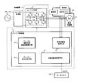
- FIG. 1 is a block diagram showing a configuration of a control device for an electric compressor according to Embodiment 1 of the present invention.
- the control device 1 is interposed between an AC / DC converter 101 connected to a commercial power source 100 and an electric compressor 102 constituting a refrigeration cycle of a refrigerator.
- the AC / DC converter 101 converts AC power supplied from the commercial power supply 100 into DC power and outputs it.
- the electric compressor 102 includes an electric element and a compression element that sucks and discharges the refrigerant thereby, and includes a DC motor 103 as the electric element.
- a brushless DC motor having three phases (U phase, V phase, W phase) is employed as the DC motor 103.
- the control device 1 includes an inverter circuit 2 and an inverter controller 3.
- the inverter circuit 2 has a configuration in which six switching elements (for example, IGBT; insulation type bipolar transistor) SW1 to SW6 are connected in a three-phase bridge. Then, the DC power input from the AC / DC converter 101 to the inverter circuit 2 is selectively output to each phase of the stator as drive power for driving the DC motor 103.
- the inverter controller 3 is configured by an arithmetic unit such as an MPU, and controls on / off switching of the switching elements SW1 to SW6 of the inverter circuit 2.
- the inverter controller 3 generates a drive signal from the commutation frequency for switching the energization phase of the stator of the DC motor 103 and the duty ratio of the PWM signal corresponding to the operating load of the DC motor 103, and outputs this drive signal to the inverter circuit 2. Output to.
- the inverter controller 3 includes target rotation speed setting means 10, measured rotation speed acquisition means 20, duty adjustment means (rotation speed control means) 30, and duty change acquisition means 40.
- the target rotational speed setting means 10 appropriately sets the target rotational speed Rt of the DC motor 103 when the refrigerator internal temperature is high and the electric compressor 102 is to be operated.
- the thermostat 104 is provided in the refrigerator which mounts the control apparatus 1 in order to detect the internal temperature.
- the thermostat 104 outputs an on signal if the internal temperature is equal to or higher than a predetermined threshold Th, and outputs an off signal if the internal temperature is lower than the threshold Th. Therefore, the target rotational speed setting means 10 acquires a signal from the thermostat, and if this is an ON signal, the internal temperature is equal to or higher than the threshold value Th, so that it is determined that “the electric compressor 102 should be operated”.
- the threshold value Th of the thermostat 104 is a set temperature in the refrigerator, and may be changed and set by a user operation.
- the actual rotation speed acquisition means 20 acquires the actual rotation speed Rm, which is a measured value of the rotation speed of the DC motor 103, over time. For example, a position detection signal indicating that the rotor is at a predetermined position is acquired from the back electromotive voltage of the DC motor 103 at a predetermined sampling period. Then, the actual number of revolutions of the DC motor 103 is calculated by counting position detection signals during a predetermined period.
- the duty adjusting means 30 adjusts the duty ratio of the driving power output from the inverter circuit 2 so that the target rotational speed Rt of the DC motor 103 and the measured rotational speed Rm coincide. This will be described more specifically.
- the timing (commutation frequency) for switching the energized phase of the stator is the current time of the DC motor 103. It is determined based on the rotational speed (actual rotational speed Rm). However, even when the DC motor 103 is to be operated at a constant rotation speed (a constant commutation frequency), the ease of rotation of the DC motor 103 varies depending on the cooling load.
- the voltage value applied to the energized phase is subjected to pulse width modulation (PWM), and the duty ratio, which is the ratio of the on time within the carrier cycle, is adjusted based on the cooling load.
- PWM pulse width modulation
- the cooling load directly depends on the inside temperature or the outside temperature.
- the internal temperature decreases as the operating time of the electric compressor 102 elapses, and the cooling load decreases accordingly. Therefore, to maintain the rotation speed of the DC motor 103 at a constant value, it is necessary to reduce the duty ratio in accordance with a reduction in cooling load (that is, a decrease in the internal temperature).
- the duty adjustment unit 30 operates while controlling the rotation speed of the DC motor 103 (actual rotation speed Rm) so as to match the target rotation speed Rt. Adjust. More specifically, if the commutation frequency and the duty ratio are constant, the actually measured rotational speed Rm of the DC motor 103 changes with a change in the cooling load. Therefore, the duty adjusting means 30 adjusts the duty ratio so that the change in the actually measured rotational speed Rm falls within the predetermined range ⁇ R, so that the target rotational speed Rt and the actually measured rotational speed Rm substantially match each other. ing.
- the duty change acquisition means 40 acquires the duty ratio with time by acquiring the duty ratio adjusted and set by the duty adjustment means 30 with time. For example, when the DC motor 103 is operated at a constant rotation speed (a constant commutation frequency), the amount of change in the duty ratio before and after a predetermined time has elapsed is acquired. Thereby, it is possible to grasp how much the cooling load has changed with the passage of the predetermined time.
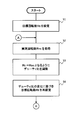
- FIG. 2 is a flowchart showing an operation procedure of the control device 1 according to the first embodiment.
- the target rotational speed setting means 10 of the control device 1 sets the target rotational speed Rt of the DC motor 103 to a predetermined value (step S1). Moreover, the actual rotation speed acquisition means 20 acquires the actual rotation speed Rt of the DC motor 103 over time (step S2). Then, the duty adjusting means 30 changes the difference value between the target rotational speed Rt set in step S1 and the actual rotational speed Rm acquired over time in step S2 (change in cooling load). Based on the above, the duty ratio is adjusted (step S3). Further, the target rotational speed setting means 10 appropriately resets the target rotational speed Rt based on the change of the duty ratio with time (step S4).
- the “change in duty ratio” in step S4 is acquired by the duty change acquisition means 40 based on the duty ratio set by the duty adjustment means 30, and this is input to the target rotation speed setting means 10.
- the following aspects can be employ
- the target rotational speed Rt is updated to a value that is significantly increased from the current value, thereby further promoting the decrease in the internal temperature.
- the difference value of the duty ratio may be set in more stages (three or more stages) than the above, and a different target rotational speed Rt may be reset according to each stage. In this way, the electric compressor 102 can be operated at a more appropriate number of revolutions according to the current cooling load without changing hardware specifications.
- Step S4 the processing from Step S2 is performed based on the updated target rotational speed Rt.
- the output of the thermostat 104 is switched from the on signal to the off signal.
- the target rotational speed setting means 10 receives the off signal from the thermostat 104, the target rotational speed setting means 10 sets the target rotational speed Rt to zero.
- the DC motor 103 is controlled so that the number of rotations becomes zero, and finally stops.
- control device 1 According to the control device 1 and its operation as described above, energy saving is achieved by operating the electric compressor according to the load while suppressing the high cost without detecting the details of the internal temperature and the outside air temperature. Can be planned. That is, the control device 1 according to the present embodiment reads the cooling load from the change in the duty ratio during the period in which the rotation speed of the DC motor 103 is kept constant. Therefore, the target rotational speed Rt of the DC motor 103 can be appropriately set based on the change in the duty ratio without providing expensive internal temperature detecting means and outside air temperature detecting means.
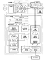
- FIG. 3 is a block diagram illustrating a configuration of the control device for the electric compressor according to the second embodiment.
- the control device 1 according to the second embodiment is provided between the AC / DC converter 101 connected to the commercial power source 100 and the electric compressor 102 that constitutes the refrigeration cycle of the refrigerator. It is intervened.
- the control device 1 also includes an inverter circuit 2 and an inverter controller 3 having a target rotational speed setting unit 10, an actual rotational speed acquisition unit 20, a duty adjustment unit 30, and a duty change acquisition unit 40.
- the target rotation speed setting means 10 has an operation state determination means (compressor operation detection means) 11 and a rotation speed setting means 12.
- the operation state determination means 11 receives the signal from the thermostat 104, and determines the target operation state of the electric compressor 102 based on this signal. For example, when an ON signal (internal temperature ⁇ Th) is received from the thermostat 104, it is determined that the electric compressor 102 is in a state to be operated. When an off signal (internal temperature ⁇ Th) is received, it is determined that the electric compressor 102 is in a state to be stopped.
- the rotation speed setting means 12 sets the target rotation speed Rt to a predetermined value larger than zero when the electric compressor 102 is in a state to be operated.
- a predetermined value for example, the number of operations that can achieve the maximum efficiency in terms of fuel consumption, or the minimum number of rotations that can be stably operated, determined from the specifications of the electric compressor 102 can be adopted.
- the target rotational speed Rt is reset based on the change in the duty ratio.
- the target rotational speed Rt is set to a zero value.
- the measured rotation speed acquisition means 20 has a position detection means 21 and a rotation speed calculation means 22.
- the position detection means 21 acquires, for example, a position detection signal indicating that the rotor is at a predetermined position from the back electromotive voltage of the DC motor 103 at a predetermined sampling period.
- the rotational speed calculation means 22 calculates the actual rotational speed Rm of the DC motor 103 by, for example, counting the position detection signal during a predetermined period.
- the inverter controller 3 includes commutation frequency setting means 50.
- the commutation frequency setting means 50 acquires a position detection signal from the position detection means 21 described above.
- the position detection signal is used to generate a commutation pulse signal that determines the switching frequency (commutation frequency) of the energized phase of the stator.
- the inverter controller 3 includes a rotation speed comparison means 51.
- the output from the rotation speed comparison means 51 to the duty adjustment means 30 means an instruction to increase the duty ratio.
- the output from the rotational speed comparison means 51 to the duty adjustment means 30 means an instruction to reduce the duty ratio. Therefore, the duty adjustment means 30 adjusts (increases, decreases or maintains) the duty ratio based on the input from the rotation speed comparison means 51 and sets it. Note that when the duty adjustment unit 30 increases the duty ratio, the voltage of the driving power to the DC motor 103 increases, and when the duty ratio is decreased, the voltage of the driving power decreases.
- the inverter controller 3 further includes drive signal synthesis means 52 and an interface 53.
- the drive signal synthesizing unit 52 synthesizes the commutation pulse signal having the commutation frequency set by the commutation frequency setting unit 50 and the PWM signal having the duty ratio set by the duty adjustment unit 30, and the inverter circuit 2.
- Drive signals for driving the switching elements SW1 to SW6 are generated.
- This drive signal is output to the inverter circuit 2 through the interface 53 including a photocoupler, and the inverter circuit 2 operates based on this drive signal.
- the driving power supplied from the AC / DC converter 101 to the DC motor 103 is distributed to each phase of the DC motor 103 at a period specified by the commutation frequency, and the voltage waveform is the duty ratio. It will have.
- the duty change acquisition means 40 includes a duty storage means 41, a time measurement means 42, and a duty comparison means 43.
- the duty storage means 41 stores the duty ratio D1 at that time set by the duty adjustment means 30 at a predetermined timing.
- the timing when the measured rotational speed Rm and the target rotational speed Rt coincide with each other is set as the timing.
- the duty storage means 41 is input with information indicating the difference value between the actually measured rotational speed Rm and the target rotational speed Rt from the rotational speed comparison means 51 described above.
- the measured rotational speed Rm and the target rotational speed Rt match does not mean only the complete coincidence of both, but within a predetermined range including the target rotational speed Rt (for example, in the first embodiment) It may be defined that the measured rotational speed Rm exists in the described rotational speed range ⁇ R).
- the time counting means 42 is based on the time when the target operating state determined by the operating state determining means 11 is switched from “stop” to “running” or when the target rotational speed Rt changes from zero to another value. And the elapsed time thereafter is measured.
- the change in the target rotational speed Rt is used as a reference. Therefore, a signal indicating the target rotational speed Rt is output from the rotational speed setting means 12 to the time measuring means 42.
- the time measuring means 42 detects the time when the target rotational speed Rt has changed from zero to another value as the reference time.
- the duty comparing means 43 acquires the duty ratio D2 at that time from the duty adjusting means 30. Also, the duty ratio D1 already stored in the duty storage means 41 is acquired. Then, a difference value between these duty ratios D 1 and D 2 is calculated, and this difference value is output to the rotation speed setting means 12. The rotation speed setting means 12 resets the target rotation speed Rt according to the acquired difference value.
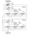
- FIG. 4 is a flowchart showing an operation procedure of the control device 1 according to the second embodiment.
- the operation state determination means 11 of the control device 1 determines whether the target operation state of the electric compressor 102 is “a state to be operated” or “a state to be stopped” based on an input signal from the thermostat 104. Are determined (step S10).
- the determination result is “a state to be stopped” (S10: NO)
- a predetermined process for stopping the electric compressor 102 including a process for maintaining the stopped state
- step S11 the operation is performed in a predetermined activation mode (step S11).
- This start mode is a predetermined operation sequence for starting the electric compressor 102 in a stopped state.
- the position detector 21 cannot detect the counter electromotive voltage of the DC motor 103, and therefore cannot detect the rotor position.
- a change in the duty ratio that is an index of the cooling load cannot be detected. Therefore, in the start mode, regardless of the position of the rotor and the cooling load, a predetermined initial value is adopted as the commutation frequency and the duty ratio to generate a drive signal, and the DC motor 103 is started.
- the activation mode is terminated when a predetermined condition is satisfied.
- this predetermined condition it is required that at least the position detection unit 21 can acquire the position detection signal and can generate the drive signal from the commutation frequency and the duty ratio.
- the target rotation speed setting means 10 sets a first target rotation speed Rt1 (for example, 1,600 rpm) (step S12).
- a first target rotation speed Rt1 for example, 1,600 rpm
- the number of operations that can achieve the maximum efficiency in terms of fuel consumption which is determined from the specifications of the electric compressor 102, can be adopted as described above.
- the time measuring means 42 starts measuring the subsequent passage of time (step S13), and stores the duty ratio D1 at that time in the duty storage means 41 (step S14). Then, it is determined whether or not a predetermined time (for example, 5 minutes or 10 minutes) has elapsed since the start of measurement (step S15).
- a process of generating a drive signal by mainly adjusting the duty ratio while maintaining the current target rotational speed is executed.
- processing for resetting the target rotational speed in accordance with the cooling load is executed.
- the actual rotation speed acquisition means 20 generates a position detection signal based on the back electromotive voltage of the DC motor 103, and acquires the actual rotation speed Rm based on this position detection signal (step S20).
- the position detection signal is output to the commutation frequency setting means 50, and the signal indicating the actually measured rotation speed Rm is output to the rotation speed comparison means 51.
- the commutation frequency setting means 50 sets the commutation frequency using the acquired position detection signal (step S21).
- the rotation speed comparison means 51 acquires a difference value between the actual rotation speed Rm and the target rotation speed Rt, and outputs this to the duty adjustment means 30.
- the duty adjustment means 30 adjusts and sets the duty ratio based on this difference value (step S21). That is, if Rm ⁇ Rt ⁇ 0, the duty ratio is increased, and if Rm ⁇ Rt> 0, the duty ratio is decreased.
- the commutation frequency and the duty ratio set in this way are input to the drive signal combining means 52.
- the drive signal synthesizing unit 52 generates a drive signal based on the commutation frequency and the duty ratio (step S22). That is, a drive signal is generated by taking the logical product of the signal having the commutation frequency and the signal having the duty ratio.
- This drive signal is output to the inverter circuit 2 via the interface 53, and operates each of the switching elements SW1 to SW6.
- the DC power from the AC / DC converter 101 becomes drive power having the commutation frequency and the duty ratio set in step S21 and is transmitted to each energized phase of the stator of the DC motor 103. Accordingly, the DC motor 103 is controlled so that the actually measured rotational speed Rm matches the target rotational speed Rt.
- the target state determination means 11 again determines the current target operation state (step S23). If the determination result is “a state to be operated” (S23: YES), it means that the internal temperature has not decreased to the threshold value Th that turns off the thermostat 104. Repeat the process. Moreover, when the determination result is “state to be stopped” (S23: NO), it means that the internal temperature has decreased to the threshold Th. Therefore, the time measurement by the time measuring means 42 is cleared (step S24), and the operation of the electric compressor 102 is stopped (step S25).
- step S20 After setting the target rotational speed (S12) and storing the duty ratio (S14), the operations in and after step S20 are repeated until a predetermined time elapses. Then, the target rotational speed set in step S12 is maintained, and the duty ratio is adjusted to control the rotational speed of the DC motor 103. If the actually measured rotational speed Rm reaches the target rotational speed Rt during this time, the DC motor 103 is stopped based on the OFF signal from the thermostat 104 (S25).
- the degree of the cooling load is determined from the degree of decrease in the duty ratio before and after the elapse of the predetermined time.
- Step S32 the difference value of the duty ratio being equal to or greater than the predetermined value X% means that the internal temperature has decreased relatively by cooling for a predetermined time, but has not reached the threshold Th at which the thermostat 104 is turned off. It means not. Therefore, the process of step S32 is intended to increase the cooling capacity by slightly increasing the target rotational speed Rt and to reach the internal temperature to the threshold Th earlier.
- the target rotational speed Rt is set to a third target rotational speed Rt3 (for example, 3,000 rpm) that is significantly increased (step 3000).
- the difference value of the duty ratio being less than the predetermined value X% means that the internal temperature is not sufficiently lowered despite the cooling for a predetermined time. For example, as such a case, it is assumed that as a result of storing hot food in the refrigerator, the internal temperature becomes significantly higher than the set temperature (threshold value Th) and the cooling load increases. Therefore, the process of step S33 is intended to drastically increase the cooling capacity by greatly increasing the target rotational speed Rt and to make the internal temperature reach the threshold Th earlier.
- step S34 the time measurement by the time measuring means 42 is cleared (restarted) (step S34), and the processing from step S14 is repeated.
- the target rotational speed of the DC motor can be appropriately set based on the change in the duty ratio.
- the DC motor can be operated at an appropriate number of revolutions without acquiring the detailed change state of the internal temperature and the outside air temperature. Therefore, it is possible to cool the interior to an appropriate temperature and to save energy while suppressing an increase in cost.
- the degree of change in the duty ratio is classified into two of X% or more and less than X%, but is not limited to this.
- the degree of change in the duty ratio is classified into three or more, and the reset value of the target rotation speed Rt may be determined so as to correspond to each classification.
- the method for setting the reset value of the target rotational speed Rt is not particularly limited.
- the value of the target rotation speed after resetting may be set as it is (2,400 rpm), or only the increment value (800 rpm) of the target rotation speed is set. May be set.
- the ratio (150%) of the target rotational speed Rt before and after the resetting, or the ratio (50%) of the increment to the value before the resetting may be set.
- the temperature sensing part is disposed at a location where the internal temperature can be detected, and the switch part is connected from the commercial power source 100 to the control device 1 (particularly, the inverter controller 3). It may be arranged on the feeder line. Accordingly, when the internal temperature sufficiently decreases and the temperature sensing unit detects that the temperature is less than the threshold Th, the switch unit operates to cut off the power supply from the commercial power supply 100 to the control device 1. Therefore, when the internal temperature is less than the threshold value Th, power is not supplied to the control device 1, and energy saving during standby can be achieved.
- the control device 1 acquires the current duty ratio while operating the DC motor 103 at a constant rotational speed, and after the time set based on this, the target rotational speed Rt Control to increase.
- the control device 1 acquires a voltage value of power input to the inverter circuit 2 (hereinafter referred to as a power supply voltage). Then, the set time based on the duty ratio (time until the target rotation speed Rt is increased) is adjusted according to the power supply voltage.
- the duty ratio is influenced not only by the cooling load but also by the magnitude of the power supply voltage.
- the control device 1 decreases the duty ratio. Conversely, when the power supply voltage is low, the control device 1 increases the duty ratio in order to keep the voltage of the driving power constant.
- the duty ratio, the cooling load, and the power supply voltage are correlated with each other.
- the cooling load can be grasped more accurately by considering not only the duty ratio but also the power supply voltage.
- the control device 1 regards that the cooling load is large and increases the target rotational speed Rt after a short time has elapsed.
- the control device 1 switches the duty ratio threshold value so that a smaller value is used when the power supply voltage is high and a larger value is used when the power supply voltage is low. Do.
- FIG. 5 is a block diagram showing the configuration of the control device for the electric compressor according to the third embodiment of the present invention.
- the control device 1 shown in FIG. 5 has the same configuration as that of the control device 1 (see FIG. 3) according to the second embodiment.
- the duty change acquisition means 40 is not provided, but a voltage detection means 60 and a switching time setting means 61 are provided. In addition, it is good also as providing the voltage detection means 60 and the switching time setting means 61 with respect to the control apparatus 1 of Embodiment 2 provided with the duty change acquisition means 40.
- the voltage detection means 60 detects the power supply voltage (DC voltage) output from the AC / DC converter 101 and input to the inverter circuit 2, and outputs the power supply voltage to the switching time setting means 61.
- the switching time setting unit 61 obtains the duty ratio when the DC motor 103 is operated at a predetermined constant rotation number from the duty adjustment unit 30, compares the duty ratio with a threshold value according to the input power supply voltage, The time until the target rotational speed Rt is increased is set. In addition, the elapsed time is measured together with the time setting.
- symbol is attached
- FIG. 6 is a flowchart showing the operation procedure of the control device according to the third embodiment
- FIG. 7 is a flowchart showing the contents of the time setting process in the operation procedure of the control device.
- the control device 1 determines whether the target operating state of the electric compressor 102 is “a state to be operated” or “a state to be stopped” based on an input signal from the thermostat 104 (step S ⁇ b> 40). ). If the determination result is “state to be stopped” (S40: NO), the time measured by the switching time setting means 61 is cleared (step S50), and a predetermined operation stop process is performed (step S51).
- the target rotational speed setting means 10 sets the target rotational speed Rt (step S42).
- the target rotational speed Rt a minimum rotational speed that can be stably operated, a highly efficient rotational speed, or the like can be set in advance.
- step S43 processing for setting a time until the target rotational speed Rt is increased.
- the time is set by using the power supply voltage acquired in step S41 and the duty ratio separately acquired from the duty adjustment means 30.
- step S100 it is first determined whether or not the power supply voltage is equal to or higher than a reference value (step S100).
- this reference value it can be set, for example to 260V.
- the AC / DC converter 101 is configured to use a voltage doubler rectification method when the effective value of the AC voltage of the commercial power supply 100 is 100V, and therefore the normal power supply voltage is about 282V.
- the AC / DC converter 101 is configured to use the full-voltage rectification method, so that the normal supply voltage is also about 282V. Therefore, a value slightly lower than the normal supply voltage can be set as the determination reference value in step S100.
- the time is set based on a threshold value of a duty ratio (for example, 20% and 30%) prepared in advance corresponding to the case where the power supply voltage is high (example: 20%, 30%).
- Steps S101 to S105 it is determined whether or not the current duty ratio acquired from the duty adjustment means 30 is 20% (first threshold value) or less (step S101). If it is 20% or less (S101: YES), the first time corresponding to the low load at the time of high voltage (eg, 30 minutes) is set as the elapsed time until the target rotational speed Rt is increased (step S102). .
- step S103 If it is greater than 20% (S101: NO), it is determined whether it is 30% (second threshold) or less (step S103). And if it is 30% or less (S103: YES), the 2nd time (example: 20 minutes) corresponding to the medium load at the time of a high voltage will be set as elapsed time (step S104). If it is greater than 30% (S103: NO), the third time (eg, 10 minutes) corresponding to the high load at the time of high voltage is set as the elapsed time (step S105).
- step S106 when the power supply voltage is less than the reference value (S100: NO), the time setting is performed based on the threshold value of the duty ratio (for example, 22% and 33%) prepared in advance corresponding to the case where the power supply voltage is low. Performed (steps S106 to S110). That is, it is determined whether or not the current duty ratio acquired from the duty adjustment means 30 is 22% (third threshold value) or less (step S106). If it is 22% or less (S106: YES), a fourth time (eg, 30 minutes) corresponding to a low load at a low voltage is set as the elapsed time (step S107).
- the threshold value of the duty ratio for example, 22% and 33%) prepared in advance corresponding to the case where the power supply voltage is low.
- step S108 If it is larger than 22% (S106: NO), it is determined whether it is 33% (fourth threshold) or less (step S108). And if it is 33% or less (S108: YES), the 5th time (example: 20 minutes) corresponding to the medium load at the time of a low voltage will be set as elapsed time (step S109). On the other hand, if it is greater than 33% (S108: NO), the sixth time (for example, 10 minutes) corresponding to the high load at the time of low voltage is set as the elapsed time (step S110).
- the first to fourth threshold values related to the duty ratio are set such that the first threshold value ⁇ the third threshold value and the second threshold value ⁇ the fourth threshold value. This is because the duty ratio varies depending on the power supply voltage even when the cooling load is the same.
- the elapsed time to be set is set so that the first time> the second time> the third time, the fourth time> the fifth time> the sixth time. This is because the duty ratio varies depending on the cooling load even when the power supply voltage is constant.
- the threshold value of the duty ratio can be set as appropriate depending on the specifications of the DC motor 103 and the refrigerator.
- one of the control method of the first or second embodiment and the control method of the third embodiment is selectively executed. Possible configurations can be obtained.
- a control method that organically combines the control method of the first or second embodiment and the control method of the third embodiment may be executed. For example, first, according to the control method of the third embodiment, the time until the target rotational speed Rt is increased is set (S43). Next, measurement of elapsed time is started (S44, S13), and when the set time has elapsed (S46: YES, S15: YES), the target rotational speed Rt is increased (reset) (S47).
- the target rotational speed Rt to be reset at this time is determined according to the control method (S30 to S33) of the first or second embodiment.
- the present invention can be applied to a method for controlling an electric compressor that can appropriately cool the inside of a refrigerator while suppressing an increase in cost and that is intended to save energy.
Landscapes
- Engineering & Computer Science (AREA)
- Mechanical Engineering (AREA)
- General Engineering & Computer Science (AREA)
- Control Of Motors That Do Not Use Commutators (AREA)
- Devices That Are Associated With Refrigeration Equipment (AREA)
- Control Of Positive-Displacement Pumps (AREA)
Abstract
Priority Applications (3)
| Application Number | Priority Date | Filing Date | Title |
|---|---|---|---|
| CN201380006512.2A CN104066991B (zh) | 2012-03-02 | 2013-03-01 | 电动压缩机的控制方法、控制装置和冷藏库 |
| JP2013532000A JP5378630B1 (ja) | 2012-03-02 | 2013-03-01 | 電動圧縮機の制御方法、制御装置、及び冷蔵庫 |
| US14/126,298 US9611851B2 (en) | 2012-03-02 | 2013-03-01 | Control method of electric compressor, controller, and refrigerator |
Applications Claiming Priority (4)
| Application Number | Priority Date | Filing Date | Title |
|---|---|---|---|
| JP2012046199 | 2012-03-02 | ||
| JP2012-046199 | 2012-03-02 | ||
| JP2013002273 | 2013-01-10 | ||
| JP2013-002273 | 2013-01-10 |
Publications (1)
| Publication Number | Publication Date |
|---|---|
| WO2013128946A1 true WO2013128946A1 (fr) | 2013-09-06 |
Family
ID=49082157
Family Applications (1)
| Application Number | Title | Priority Date | Filing Date |
|---|---|---|---|
| PCT/JP2013/001282 Ceased WO2013128946A1 (fr) | 2012-03-02 | 2013-03-01 | Procédé pour commander un compresseur électrique, dispositif de commande et réfrigérateur |
Country Status (4)
| Country | Link |
|---|---|
| US (1) | US9611851B2 (fr) |
| JP (1) | JP5378630B1 (fr) |
| CN (1) | CN104066991B (fr) |
| WO (1) | WO2013128946A1 (fr) |
Families Citing this family (8)
| Publication number | Priority date | Publication date | Assignee | Title |
|---|---|---|---|---|
| US20150333675A1 (en) * | 2014-05-16 | 2015-11-19 | GM Global Technology Operations LLC | Methods and systems to improve dc motor cooling fan efficiency with pulse width modulation frequency variation |
| US9502999B2 (en) * | 2014-06-27 | 2016-11-22 | Iucf-Hyu (Industry-University Cooperation Foundation Hanyang University) | Apparatus for driving motor and controlling method thereof |
| CN106481537B (zh) * | 2016-11-25 | 2018-11-27 | 广东美的制冷设备有限公司 | 压缩机的控制方法、装置和家用电器 |
| JP2018087535A (ja) * | 2016-11-29 | 2018-06-07 | 三菱重工サーマルシステムズ株式会社 | 回転速度制御装置、ロータリ圧縮機システム、制御システム及び回転速度制御方法 |
| JP6622263B2 (ja) * | 2017-07-28 | 2019-12-18 | ミネベアミツミ株式会社 | モータ駆動制御装置及びモータの駆動制御方法 |
| US20190326838A1 (en) * | 2018-04-24 | 2019-10-24 | Graco Minnesota Inc. | Pulse width modulation motor control of pressurizer pump |
| CN117287890A (zh) * | 2022-06-17 | 2023-12-26 | 重庆海尔制冷电器有限公司 | 一种冰箱及其压缩机控制方法 |
| CN115037199A (zh) * | 2022-07-19 | 2022-09-09 | 宁波森瑞机电技术有限公司 | 一种直流电机控制方法和存储介质 |
Citations (5)
| Publication number | Priority date | Publication date | Assignee | Title |
|---|---|---|---|---|
| JPS5637441A (en) * | 1979-09-03 | 1981-04-11 | Toshiba Corp | Control device for air conditioner |
| JPH0988837A (ja) * | 1995-09-29 | 1997-03-31 | Matsushita Refrig Co Ltd | 圧縮機電動機制御装置 |
| JP2001268967A (ja) * | 2000-03-23 | 2001-09-28 | Sharp Corp | 圧縮機モータの制御装置 |
| JP2002027777A (ja) * | 2000-07-05 | 2002-01-25 | Sharp Corp | モータのトルク制御方法 |
| JP2008101531A (ja) * | 2006-10-19 | 2008-05-01 | Matsushita Electric Ind Co Ltd | 圧縮機の制御装置 |
Family Cites Families (8)
| Publication number | Priority date | Publication date | Assignee | Title |
|---|---|---|---|---|
| JPH0621757B2 (ja) | 1985-07-04 | 1994-03-23 | 松下冷機株式会社 | 冷蔵庫の運転制御装置 |
| US4734628A (en) * | 1986-12-01 | 1988-03-29 | Carrier Corporation | Electrically commutated, variable speed compressor control system |
| CN1070657C (zh) * | 1995-10-06 | 2001-09-05 | 株式会社日立制作所 | 电动机控制器 |
| US6603280B2 (en) * | 1998-04-02 | 2003-08-05 | Hitachi, Ltd. | Motor controller |
| KR100702913B1 (ko) * | 2003-03-17 | 2007-04-03 | 마쯔시다덴기산교 가부시키가이샤 | 브러시리스 dc 모터의 구동 방법 및 그 장치 |
| CN100395954C (zh) * | 2003-04-22 | 2008-06-18 | 松下电器产业株式会社 | 电动机控制装置、压缩机、空调机、和冷藏库 |
| JP2006025565A (ja) * | 2004-07-09 | 2006-01-26 | Matsushita Electric Ind Co Ltd | インバータ回路および圧縮機 |
| JP4474436B2 (ja) * | 2007-05-09 | 2010-06-02 | シャープ株式会社 | 力率改善回路、モータ駆動装置及び空気調和機 |
-
2013
- 2013-03-01 WO PCT/JP2013/001282 patent/WO2013128946A1/fr not_active Ceased
- 2013-03-01 US US14/126,298 patent/US9611851B2/en not_active Expired - Fee Related
- 2013-03-01 CN CN201380006512.2A patent/CN104066991B/zh active Active
- 2013-03-01 JP JP2013532000A patent/JP5378630B1/ja not_active Expired - Fee Related
Patent Citations (5)
| Publication number | Priority date | Publication date | Assignee | Title |
|---|---|---|---|---|
| JPS5637441A (en) * | 1979-09-03 | 1981-04-11 | Toshiba Corp | Control device for air conditioner |
| JPH0988837A (ja) * | 1995-09-29 | 1997-03-31 | Matsushita Refrig Co Ltd | 圧縮機電動機制御装置 |
| JP2001268967A (ja) * | 2000-03-23 | 2001-09-28 | Sharp Corp | 圧縮機モータの制御装置 |
| JP2002027777A (ja) * | 2000-07-05 | 2002-01-25 | Sharp Corp | モータのトルク制御方法 |
| JP2008101531A (ja) * | 2006-10-19 | 2008-05-01 | Matsushita Electric Ind Co Ltd | 圧縮機の制御装置 |
Also Published As
| Publication number | Publication date |
|---|---|
| US9611851B2 (en) | 2017-04-04 |
| JPWO2013128946A1 (ja) | 2015-07-30 |
| CN104066991A (zh) | 2014-09-24 |
| JP5378630B1 (ja) | 2013-12-25 |
| CN104066991B (zh) | 2016-03-30 |
| US20140105754A1 (en) | 2014-04-17 |
Similar Documents
| Publication | Publication Date | Title |
|---|---|---|
| JP5378630B1 (ja) | 電動圧縮機の制御方法、制御装置、及び冷蔵庫 | |
| EP3447896B1 (fr) | Systèmes de commande de moteur | |
| US20130064684A1 (en) | Controller of compressor | |
| EP2863537B1 (fr) | Dispositif de commande de moteur | |
| CN107960145A (zh) | 电动机驱动装置、和使用其的压缩机的驱动装置以及冷藏库 | |
| CN103326664A (zh) | 电动机控制装置及利用其的电动机驱动装置、压缩机、冷冻装置、空气调节器、以及电动机控制方法 | |
| TWI355477B (fr) | ||
| JP2008289310A (ja) | モータ駆動装置およびこれを用いた冷蔵庫 | |
| JP3672637B2 (ja) | 圧縮機電動機制御装置 | |
| JP2001263256A (ja) | 圧縮機の制御装置 | |
| US20180145616A1 (en) | Dc-brushless-motor control device | |
| KR20060106189A (ko) | 두개의 왕복동식 압축기를 구비한 냉장고의 운전제어장치 | |
| JP3776102B2 (ja) | ブラシレスモータ制御装置 | |
| US9657980B2 (en) | Motor driving apparatus and refrigerator including same | |
| JP2014234718A (ja) | 圧縮機の制御装置および冷蔵庫 | |
| KR101766244B1 (ko) | 압축기 제어 장치와 방법, 및 이를 포함한 냉장고 | |
| JP6970871B2 (ja) | モータ駆動装置および、これを用いた冷蔵庫 | |
| JP2013011219A (ja) | 圧縮機の制御装置 | |
| JP4682414B2 (ja) | 収納庫 | |
| JP6093606B2 (ja) | モータ駆動装置 | |
| WO2022176615A1 (fr) | Entraînement de moteur et réfrigérateur l'utilisant | |
| JP2005083683A (ja) | 冷蔵庫及びその運転制御方法 | |
| JP2008005639A (ja) | ブラシレスdcモータの駆動方法およびその装置 | |
| JP2006223014A (ja) | モータ駆動装置 | |
| JP2012200112A (ja) | 圧縮機の制御装置 |
Legal Events
| Date | Code | Title | Description |
|---|---|---|---|
| WWE | Wipo information: entry into national phase |
Ref document number: 201380006512.2 Country of ref document: CN |
|
| ENP | Entry into the national phase |
Ref document number: 2013532000 Country of ref document: JP Kind code of ref document: A |
|
| 121 | Ep: the epo has been informed by wipo that ep was designated in this application |
Ref document number: 13754873 Country of ref document: EP Kind code of ref document: A1 |
|
| WWE | Wipo information: entry into national phase |
Ref document number: 14126298 Country of ref document: US |
|
| NENP | Non-entry into the national phase |
Ref country code: DE |
|
| 122 | Ep: pct application non-entry in european phase |
Ref document number: 13754873 Country of ref document: EP Kind code of ref document: A1 |