WO2013129072A1 - Source de rayons x - Google Patents
Source de rayons x Download PDFInfo
- Publication number
- WO2013129072A1 WO2013129072A1 PCT/JP2013/052926 JP2013052926W WO2013129072A1 WO 2013129072 A1 WO2013129072 A1 WO 2013129072A1 JP 2013052926 W JP2013052926 W JP 2013052926W WO 2013129072 A1 WO2013129072 A1 WO 2013129072A1
- Authority
- WO
- WIPO (PCT)
- Prior art keywords
- ray irradiation
- ray
- facing surface
- irradiation source
- holding member
- Prior art date
- Legal status (The legal status is an assumption and is not a legal conclusion. Google has not performed a legal analysis and makes no representation as to the accuracy of the status listed.)
- Ceased
Links
Images


Classifications
-
- H—ELECTRICITY
- H01—ELECTRIC ELEMENTS
- H01J—ELECTRIC DISCHARGE TUBES OR DISCHARGE LAMPS
- H01J35/00—X-ray tubes
- H01J35/02—Details
- H01J35/04—Electrodes ; Mutual position thereof; Constructional adaptations therefor
- H01J35/045—Electrodes for controlling the current of the cathode ray, e.g. control grids
Definitions
- the present invention relates to an X-ray irradiation source including an X-ray tube in a housing.
- an X-ray irradiation apparatus provided with a plurality of X-ray irradiation sources having an X-ray generation source for generating X-rays.
- Such an X-ray irradiation apparatus is an ion gas by irradiating a gas such as air with X-rays in a manufacturing process such as an IC (Integrated Circuit), LCD (Liquid Crystal Display), or PDP (Plasma Display Panel). May be used as a static eliminator that neutralizes a target object by generating.
- This light static elimination apparatus includes a soft X-ray generator, a high-voltage power supply circuit, and a control unit, and an electron generation voltage and an acceleration voltage generated by the high-voltage power supply circuit are individually variably controlled by the control unit.
- a soft X-ray generator is attached to a support member such as a curtain rail at regular intervals so that soft X-rays can be irradiated at once in the width direction of the irradiated object.
- the support member is preferably a member such as metal from the viewpoint of durability after the device is attached.
- the facing surface of the X-ray irradiation source facing the object to be irradiated is a conductive member.
- the opposing surface is an insulating member, the opposing surface is charged under the influence of a high-voltage power source for driving the X-ray source and an external potential, thereby causing an electrostatic induction phenomenon.
- the charge removal of the object to be processed may be insufficient.
- the opposing surface is made a conductive member without taking any countermeasures, the potential of the opposing surface becomes unstable due to the influence of the induced current flowing through the support member. It is conceivable that static elimination will be insufficient.
- the present invention has been made in order to solve the above-mentioned problems, and can suppress the influence of the induced current flowing through the support member to stabilize the opposing surface electrically and sufficiently perform the charge removal of the workpiece.
- An object is to provide a radiation source.
- an X-ray irradiation source includes an X-ray tube that outputs X-rays, an X-ray emission window that houses the X-ray tube inside and emits X-rays toward the outside. And an X-ray irradiation source for irradiating an object to be irradiated with X-rays in a state of being fixed to a holding member made of metal, wherein the X-ray emission window is formed on the casing.
- the exposed surface is a first facing surface facing the object to be irradiated, and at least the first facing surface is made of a conductive member and is held by the holding member via an insulating member. It is said.
- the casing and the holding member are coupled to each other through an insulating member, and the first opposing surface having conductivity and the holding member are electrically insulated from each other.
- the influence of the induced current flowing through the support member can be suppressed from reaching the first facing surface, and the object to be processed can be sufficiently discharged without causing an electrostatic induction phenomenon.
- the first facing surface is made of a conductive member, the first facing surface is charged by the influence of a high voltage power source for driving the X-ray source or an external potential. This can be suppressed, and the charge removal effect of the workpiece can be improved.
- the housing has a second facing surface facing the holding member, and the holding member and the second facing surface are separated by an insulating member.
- the holding member has a U-shaped channel portion and a flange portion protruding laterally from the channel portion, and the insulating member includes a main body portion fixed to the second facing surface; And a claw portion that is provided on the main body portion and is detachably and slidably fitted to the flange portion.
- the holding member is preferably formed by combining divided members divided in the longitudinal direction.
- the holding member can have a desired shape and size according to the object to be processed, and the object to be processed can be discharged more efficiently.
- the opposing surface can be electrically stabilized by suppressing the influence of the induced current flowing through the support member, and the object to be treated can be sufficiently discharged.
- FIG. 1 is a perspective view showing an embodiment of an X-ray irradiation apparatus including an X-ray irradiation source according to the present invention. It is a block diagram which shows the functional component of the X-ray irradiation apparatus shown in FIG. It is a perspective view of the X-ray irradiation source shown in FIG.
- FIG. 4 is a plan view of FIG. 3.
- FIG. 5 is a cross-sectional view taken along line VV in FIG. 4. It is a figure which shows an example of the fixation structure of an X-ray tube and a 1st circuit board. It is a figure which shows an example of the fixing structure of a housing
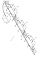
- FIG. 1 is a perspective view showing an embodiment of an X-ray irradiation apparatus including an X-ray irradiation source according to the present invention.
- the X-ray irradiation apparatus 1 shown in the figure is installed in a clean room or the like in a production line that handles large glass, for example, and is configured as a photoionizer (light irradiation type neutralization apparatus) that neutralizes large glass by irradiation with X-rays. .
- the X-ray irradiation apparatus 1 includes a plurality of X-ray irradiation sources 2 that irradiate X-rays, a controller 3 that controls the X-ray irradiation sources 2, and a rail member (holding member) 4 that holds the X-ray irradiation sources 2 side by side. And is configured.
- the rail member 4 includes a channel portion 4a having a substantially U-shaped cross section in which a recess is formed in a direction away from the X-ray irradiation source 2, and flange portions 4b and 4b protruding sideways from the end of the channel portion 4a. have.
- the rail member 4 is made of, for example, aluminum, aluminum alloy, or metal having conductivity such as iron or iron alloy, and has sufficient strength and durability to hold the plurality of X-ray irradiation sources 2. Has been.
- the rail member 4 is not restricted to what was formed integrally,
- segmented along the longitudinal direction (extension direction) may be connected detachably. In this case, a holding structure having a desired shape and size can be obtained in accordance with the size, number, arrangement, and the like of the object to be processed, so that charge removal by more efficient X-ray irradiation becomes possible.
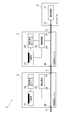
- FIG. 2 is a block diagram showing functional components of the X-ray irradiation apparatus 1.
- the controller 3 includes a control circuit 11.
- the control circuit 11 is, for example, a power supply circuit that supplies power toward an X-ray tube 21 built in the X-ray irradiation source 2, and a control signal transmission that transmits a control signal that controls driving and stopping toward the X-ray tube 21.
- the circuit includes a life notification signal receiving circuit that receives from the X-ray tube 21 a life notification signal indicating that the X-ray tube 21 has reached the end of its life.
- This control circuit 11 can be externally connected to the X-ray irradiation unit 2 or the like by an input / output terminal 12.
- the X-ray irradiation source 2 includes an X-ray tube 21 that generates X-rays, a high-voltage generation module 22 that boosts the voltage from the power supply circuit, and a drive circuit 23 that drives the X-ray tube 21 and the high-voltage generation module 22. It is comprised including.
- a trunk line 24 is connected to the drive circuit 23, and the trunk line 24 can be externally connected to other X-ray irradiation units 2, a controller 3 and the like by an input terminal 25 and an output terminal 26 provided at both ends thereof. It has become.
- the output terminal 26 of one X-ray irradiation source 2 is an input terminal of another X-ray irradiation source 2 adjacent via the relay cable C. 25 is detachably connected. While the X-ray irradiation units 2 are similarly connected to each other up to the distal X-ray irradiation unit 2, the input / output terminal 12 of the controller 3 is connected to the proximal X-ray irradiation source via the relay cable C. 2 is detachably connected to the two input terminals 25. Thereby, the trunk wiring 24 of each X-ray irradiation source 2 is connected in series to the control circuit 11, and the drive circuit 23 of each X-ray irradiation source 2 is connected in parallel to the control circuit 11.
- the value of the voltage input from the input terminal 25 of one X-ray irradiation unit 2 is equal to the value of the voltage output from the output terminal 26, and the output terminal 26 of one X-ray irradiation unit 2
- the value of the output voltage, the value of the voltage input from the input terminal 25 of another X-ray irradiation unit 2 electrically connected to one X-ray irradiation unit 2, and the voltage output from the output terminal 26 Both values are equal. For this reason, even when a plurality of X-ray irradiation units 2 are connected in a line, a voltage having an equal value can be supplied to all the X-ray irradiation units 2.
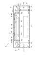
- FIG. 3 is a perspective view of the X-ray irradiation source shown in FIG. 4 is a plan view of FIG. 3, and FIG. 5 is a cross-sectional view taken along line VV in FIG.
- the X-ray irradiation source 2 includes the above-described X-ray tube 21 and high-pressure generation module 22 in a substantially rectangular parallelepiped casing 31 made of stainless steel, aluminum, or the like. It has a first circuit board 32 on which at least a part of the X-ray tube 21 and the drive circuit 23 are mounted, and a second circuit board 33 on which the high voltage generation module 22 is mounted.
- the housing 31 has a rectangular wall portion 31a formed with an X-ray emission window 34 for emitting X-rays generated from the X-ray tube 21 to the outside, and the wall portion 31a.
- a main body portion 35 having a side wall portion 31b provided on each side and having an opening on one surface side; and a lid portion 31c that faces the wall portion 31a and is attached so as to close the opening portion of the main body portion 35; It is assumed to be a potential.
- the X-ray exit window 34 is configured by an opening formed in a rectangular shape along the longitudinal direction of the housing 31 at a substantially central portion of the wall portion 31a.
- the outer surface of the wall portion 31a is a facing surface (first facing surface) P1 that faces the object to be irradiated with X-rays
- the outer surface of the lid portion 31c is a facing surface (second surface) that faces the rail member 4.
- the X-ray tube 21 includes a filament 52 for generating an electron beam, a grid 53 for accelerating the electron beam, and an incident electron beam in a substantially rectangular parallelepiped vacuum vessel 51 that is sufficiently smaller than the casing 31. And a target 54 for generating X-rays.
- the vacuum vessel 51 includes a rectangular wall portion 51a made of a conductive material (for example, a metal plate such as stainless steel) provided with an output window 57, which will be described later, and a rectangular insulating material ( For example, a wall 51b made of glass and a side wall 51c made of an insulating material (for example, glass) along the outer edges of the walls 51a and 51b are provided.
- the height of the side wall 51c is smaller than the length in the short direction of the walls 51a and 51b. That is, the vacuum container 51 has a flat plate-like substantially rectangular parallelepiped shape in which the length of the side constituting the height is the shortest and the walls 51a and 51b can be regarded as a flat plate plane.
- An opening 51d that is slightly smaller than the X-ray exit window 34 is formed in a rectangular shape along the longitudinal direction of the vacuum vessel 51 (longitudinal direction of the walls 51a and 51b) in the substantially central portion of the wall 51a. Yes.
- the opening 51d constitutes an output window 57 described later.
- the filament 52 is disposed on the wall 51b side, and the grid 53 is disposed between the filament 52 and the target 54.
- a plurality of power supply pins 55 are connected to the filament 52 and the grid 53, respectively.
- the power supply pins 55 pass between the side wall portion 51 c and the wall portion 51 b, and protrude from both sides of the vacuum vessel 51 in the width direction.
- the outer surface side of the wall 51a is made of a material having good X-ray transparency, such as beryllium, silicon, titanium, or the like so as to seal the opening 51d.
- a rectangular window member 56 is tightly fixed, and an output window 57 for outputting X-rays generated at the target 54 from the X-ray tube 21 to the outside is configured.
- the target 54 made of tungsten or the like is formed on the inner surface of the window material 56.
- the X-ray tube 21 When the X-ray tube 21 and the first circuit board 32 are fixed, as shown in FIGS. 6 (a) and 6 (b), the X-ray tube 21 is disposed substantially at the center of the first circuit board 32.
- a rectangular through-hole 32a that is slightly larger than the planar shape formed by the outermost edge on the wall 51b side is formed.
- the depth of the through hole 32 a that is, the thickness of the first circuit board 32 is substantially the same as the thickness of the wall portion 51 b in the vacuum container 51.
- the wall 51 b is located in the through hole 32 a, and each power supply pin 55 is electrically conductive such as brazing material at the edge around the through hole 32 a on the one surface side of the first circuit board 32.
- the first circuit board 32 By being connected by the member, the first circuit board 32 is held and the circuit on the first circuit board 32 is electrically connected. Further, a potting portion 58 made of an insulating resin is provided so as to cover the connection portion between each power supply pin 55 and the first circuit board 32. The potting portion 58 is formed over the entire circumference of the vacuum vessel 51 in a state of straddling the vacuum vessel 51 and the first circuit board 32, and also serves as an aid for fixing the X-ray tube 21 to the first circuit board 32. ing. On the other hand, in fixing the high voltage generation module 22 and the second circuit board 33, as shown in FIG. 5, the second circuit board 33 is not formed with a through-hole or the like. The second circuit board 33 is fixed to one surface facing the first circuit board 32 by adhesion or the like.
- spacer members 61 and 62 are used to fix the X-ray tube 21, the high voltage generation module 22, the first circuit board 32, and the second circuit board 33 in the housing 31.
- the two-stage structure is adopted.
- the spacer members 61 and 62 are formed in a rod shape from various resin materials such as ceramics, polyimide, nylon, and epoxy, and are non-conductive.
- the spacer members 61 and 62 are arranged at two locations so as to sandwich the vacuum vessel 51 in the longitudinal direction.
- the first-stage spacer member 61 is erected on the inner surface side of the lid portion 31 c of the housing 31 by fastening the screw 63, and the second-stage spacer member 62 is a second circuit board on which the high-voltage generation module 22 is mounted. It is connected to the tip of the first-stage spacer member 61 in a state where 33 is sandwiched and fixed.
- the first circuit board 32 on which the X-ray tube 21 is mounted is fixed to the tip of the second-stage spacer member 62 substantially in parallel with the second circuit board 33 by fastening screws 64.
- the lid portion 31 c provided with such a structure is aligned so that the output window 57 of the X-ray tube 21 is exposed from the X-ray emission window 34 of the housing 31, and is fixed to the main body portion 35 by fastening screws 65.
- the length of the second-stage spacer member 62 is about several times that of the first-stage spacer member 61, and the first circuit board 32 and the high-voltage generating module 22 are separated from each other.
- the connection between the first circuit board 32 and the high voltage generation module 22 may be a wired connection or a wireless connection.
- a buffer member 67 having conductivity and cushioning properties such as steel wool, conductive mat, and conductive rubber is disposed between the X-ray tube 21 and the wall 31a.
- the buffer member 67 includes an opening that exposes the output window 57 and a rectangular frame-like portion that surrounds the periphery of the output window 57 so as to be in contact with the peripheral edge of the window member 56, and electrically connects the housing 31 and the output window 57.
- the X-ray exit window 34 provided in the housing 31 is slightly larger than the output window 57 of the X-ray tube 21 so that the entire output window 57 is exposed when viewed from the facing surface P1 side. Yes.
- the X-rays emitted from the output window 57 with a divergence angle can be prevented from being blocked by the edge of the X-ray emission window 34.
- the materials that may be exposed from the X-ray exit window 34 such as the window material 56, the wall portion 51 a, and the buffer member 67 are all conductive and are electrically connected to the housing 31.
- a plurality of joint members (insulating members) 41 are used to attach the casing 31 and the rail member 4.
- the joint member 41 is formed of, for example, a resin material having insulating properties and elasticity, and is disposed at both ends of the casing 31 in the longitudinal direction.
- the joint member 41 is a main body having a rectangular shape in section with a length substantially equal to the length of the rail member 4 (direction perpendicular to the extending direction of the rail member 4). It has a portion 41a and claw portions 41b and 41b respectively formed at both ends of the main body portion 41a.
- An insertion hole 43 for inserting the screw 42 is formed in a substantially central portion of the main body 41a.
- the main body portion 41a is fixed to the lid portion 31c by screwing the screw 42 into the insertion hole 43 and attaching a nut 44 to the tip of the screw 42 inside the lid portion 31c.
- attachment, welding, etc. may be sufficient besides screwing.
- the tip of the claw portion 41b is formed thick and is bent from the end of the main body portion 41a so as to go around to the back side of the flange portion 4b, and the base end of the claw portion 41b is formed thinner than the tip.
- the deformation of the claw portion 41b due to elasticity is allowed.
- a joint member 41 is further attached between the X-ray irradiation sources 2 and 2, and an intermediate portion of the relay cable C connecting the X-ray irradiation sources 2 and 2 is connected to the rail member 4 by the joint member 41. It may be bound.
- the casing 31 and the rail member 4 are coupled via the joint member 41 having insulation, and the first facing surface P ⁇ b> 1 and the rail member 4 are mutually connected. It is electrically insulated.
- the influence of the induced current flowing through the rail member 4 when connected to the external equipment can be prevented from reaching the first facing surface P1 of the housing 31, and the workpiece can be processed without causing an electrostatic induction phenomenon. Can be sufficiently removed.
- the first facing surface P ⁇ b> 1 is made of metal, so that the first facing surface P ⁇ b> 1 is affected by the high voltage power supply module 22 for driving the X-ray tube 21 and the potential existing outside.
- all materials that may be exposed from the X-ray exit window 34 such as the window material 56, the wall portion 51a, and the buffer member 67 are also conductive. And electrically connected to the housing 31. That is, the opposing surface P1 side of the X-ray irradiation unit 2 is all a conductive member and has the same potential. Thereby, the static elimination effect of a to-be-processed object can be improved further.
- the rail member 4 includes a channel portion 4 a having a U-shaped cross section and a flange portion 4 b that protrudes laterally from the channel portion 4 a.
- 2 has a main body portion 41a fixed to the opposing surface P2, and a claw portion 41b that is detachably and slidably fitted to the flange portion 4b.
- casing 31 and the rail member 4 can be couple
- operations such as position adjustment and replacement of the X-ray irradiation source 2 can be easily performed, so that the processing target can be performed more efficiently. It is possible to carry out static elimination of things. Furthermore, since the contact part of the joint member 41 and the rail member 4 can be reduced, more reliable insulation can be performed.
- the joint member 41 the second facing surface P2 of the casing 31 is separated from the rail member 4 by the thickness of the main body portion 41a.
- the 2nd opposing surface P2 is spaced apart from the rail member 4, since between the 1st opposing surface P1 and the rail member 4 can be insulated more reliably, it fully implements static elimination of a to-be-processed object. it can.
- the present invention is not limited to the above embodiment, and various modifications can be applied as long as the first facing surface P1 and the rail member 4 in the casing 31 are electrically insulated from each other by an insulating member.
- the main body portion 35 and the lid portion 31c of the housing 31 are both formed of metal, but the lid portion 31c (or the joint portion of the lid portion 31c with the joint member 41) is made of an insulating resin. You may implement
- the joint member 41 may be made of resin or metal.
Landscapes
- Elimination Of Static Electricity (AREA)
- Analysing Materials By The Use Of Radiation (AREA)
- X-Ray Techniques (AREA)
Applications Claiming Priority (2)
| Application Number | Priority Date | Filing Date | Title |
|---|---|---|---|
| JP2012-046839 | 2012-03-02 | ||
| JP2012046839A JP5918571B2 (ja) | 2012-03-02 | 2012-03-02 | X線照射源 |
Publications (1)
| Publication Number | Publication Date |
|---|---|
| WO2013129072A1 true WO2013129072A1 (fr) | 2013-09-06 |
Family
ID=49082275
Family Applications (1)
| Application Number | Title | Priority Date | Filing Date |
|---|---|---|---|
| PCT/JP2013/052926 Ceased WO2013129072A1 (fr) | 2012-03-02 | 2013-02-07 | Source de rayons x |
Country Status (3)
| Country | Link |
|---|---|
| JP (1) | JP5918571B2 (fr) |
| TW (1) | TW201352069A (fr) |
| WO (1) | WO2013129072A1 (fr) |
Cited By (1)
| Publication number | Priority date | Publication date | Assignee | Title |
|---|---|---|---|---|
| CN103763845A (zh) * | 2014-01-29 | 2014-04-30 | 刘斌 | α辐射源在取放装置上的应用 |
Families Citing this family (1)
| Publication number | Priority date | Publication date | Assignee | Title |
|---|---|---|---|---|
| CN111157895B (zh) * | 2020-02-10 | 2022-02-25 | 哈尔滨理工大学 | 一种高压电机定子绕组端部表面电位测量系统 |
Citations (3)
| Publication number | Priority date | Publication date | Assignee | Title |
|---|---|---|---|---|
| JPS6233200U (fr) * | 1985-05-02 | 1987-02-27 | ||
| JPH034454U (fr) * | 1989-05-31 | 1991-01-17 | ||
| JP2006338965A (ja) * | 2005-05-31 | 2006-12-14 | Hamamatsu Photonics Kk | X線発生装置及び照射ユニット |
-
2012
- 2012-03-02 JP JP2012046839A patent/JP5918571B2/ja not_active Expired - Fee Related
-
2013
- 2013-02-07 WO PCT/JP2013/052926 patent/WO2013129072A1/fr not_active Ceased
- 2013-02-25 TW TW102106554A patent/TW201352069A/zh unknown
Patent Citations (3)
| Publication number | Priority date | Publication date | Assignee | Title |
|---|---|---|---|---|
| JPS6233200U (fr) * | 1985-05-02 | 1987-02-27 | ||
| JPH034454U (fr) * | 1989-05-31 | 1991-01-17 | ||
| JP2006338965A (ja) * | 2005-05-31 | 2006-12-14 | Hamamatsu Photonics Kk | X線発生装置及び照射ユニット |
Cited By (1)
| Publication number | Priority date | Publication date | Assignee | Title |
|---|---|---|---|---|
| CN103763845A (zh) * | 2014-01-29 | 2014-04-30 | 刘斌 | α辐射源在取放装置上的应用 |
Also Published As
| Publication number | Publication date |
|---|---|
| TW201352069A (zh) | 2013-12-16 |
| JP5918571B2 (ja) | 2016-05-18 |
| JP2013182814A (ja) | 2013-09-12 |
Similar Documents
| Publication | Publication Date | Title |
|---|---|---|
| KR101656781B1 (ko) | 엑스선관의 교체가 용이한 엑스선 이오나이저 | |
| TW484164B (en) | Open type X ray generator | |
| US9445487B2 (en) | X-ray irradiation device and X-ray radiation source | |
| KR20170105091A (ko) | 이온 발생 장치, 이온 발생 장치의 제조 방법 및 전기 기기 | |
| JP6063272B2 (ja) | X線照射源及びx線管 | |
| CN103996592A (zh) | 放射线管和使用该放射线管的放射线成像系统 | |
| JP5918571B2 (ja) | X線照射源 | |
| CN104145532B (zh) | X射线照射源 | |
| TWI598002B (zh) | X光照射源 | |
| JP2016520959A (ja) | X線発生装置と、これを構成するx線発生部及び高電圧発生部 | |
| JP4664025B2 (ja) | X線源 | |
| JP4762436B2 (ja) | カソードユニット及び開放型x線発生装置 | |
| KR20130112919A (ko) | 회로 부품의 실장 구조 및 회로 부품의 실장 방법 | |
| EP1944789B1 (fr) | Tube a rayons x et source de rayons x comprenant ce tube | |
| JP4829535B2 (ja) | X線発生装置及び照射ユニット | |
| JP2009157267A (ja) | プラズマディスプレイ装置 | |
| KR101211639B1 (ko) | 전극 지지수단을 구비하는 전자총 및 이를 포함하는 x선관 | |
| TW201338000A (zh) | 電子線照射裝置及電子線透過單元 | |
| JP6153768B2 (ja) | イオン発生素子およびイオン発生装置 | |
| KR101686821B1 (ko) | X선 발생기 | |
| JP2006073382A (ja) | X線源 | |
| KR101389694B1 (ko) | 탈부착 가능한 고전압 발생부와 x선 발생부를 갖는 x선 발생 장치 및 정전기 제거 장치 및 이를 구성하는 고전압 발생부와 x선 발생부 | |
| JP2015028909A (ja) | 放射線発生装置及びそれを用いた放射線撮影システム | |
| CN109690893B (zh) | 放电装置及电气设备 | |
| JP2003185800A (ja) | 電子ビーム照射装置 |
Legal Events
| Date | Code | Title | Description |
|---|---|---|---|
| 121 | Ep: the epo has been informed by wipo that ep was designated in this application |
Ref document number: 13754885 Country of ref document: EP Kind code of ref document: A1 |
|
| NENP | Non-entry into the national phase |
Ref country code: DE |
|
| 122 | Ep: pct application non-entry in european phase |
Ref document number: 13754885 Country of ref document: EP Kind code of ref document: A1 |