WO2013129083A1 - 切削インサート、切削工具および切削加工物の製造方法 - Google Patents
切削インサート、切削工具および切削加工物の製造方法 Download PDFInfo
- Publication number
- WO2013129083A1 WO2013129083A1 PCT/JP2013/053073 JP2013053073W WO2013129083A1 WO 2013129083 A1 WO2013129083 A1 WO 2013129083A1 JP 2013053073 W JP2013053073 W JP 2013053073W WO 2013129083 A1 WO2013129083 A1 WO 2013129083A1
- Authority
- WO
- WIPO (PCT)
- Prior art keywords
- cutting
- protrusion
- cutting insert
- cutting edge
- corner
- Prior art date
- Legal status (The legal status is an assumption and is not a legal conclusion. Google has not performed a legal analysis and makes no representation as to the accuracy of the status listed.)
- Ceased
Links
Images




Classifications
-
- B—PERFORMING OPERATIONS; TRANSPORTING
- B23—MACHINE TOOLS; METAL-WORKING NOT OTHERWISE PROVIDED FOR
- B23B—TURNING; BORING
- B23B27/00—Tools for turning or boring machines; Tools of a similar kind in general; Accessories therefor
- B23B27/14—Cutting tools of which the bits or tips or cutting inserts are of special material
- B23B27/16—Cutting tools of which the bits or tips or cutting inserts are of special material with exchangeable cutting bits or cutting inserts, e.g. able to be clamped
- B23B27/1603—Cutting tools of which the bits or tips or cutting inserts are of special material with exchangeable cutting bits or cutting inserts, e.g. able to be clamped with specially shaped plate-like exchangeable cutting inserts, e.g. chip-breaking groove
- B23B27/1607—Cutting tools of which the bits or tips or cutting inserts are of special material with exchangeable cutting bits or cutting inserts, e.g. able to be clamped with specially shaped plate-like exchangeable cutting inserts, e.g. chip-breaking groove characterised by having chip-breakers
-
- B—PERFORMING OPERATIONS; TRANSPORTING
- B23—MACHINE TOOLS; METAL-WORKING NOT OTHERWISE PROVIDED FOR
- B23B—TURNING; BORING
- B23B27/00—Tools for turning or boring machines; Tools of a similar kind in general; Accessories therefor
- B23B27/14—Cutting tools of which the bits or tips or cutting inserts are of special material
- B23B27/141—Specially shaped plate-like cutting inserts, i.e. length greater or equal to width, width greater than or equal to thickness
- B23B27/143—Specially shaped plate-like cutting inserts, i.e. length greater or equal to width, width greater than or equal to thickness characterised by having chip-breakers
-
- B—PERFORMING OPERATIONS; TRANSPORTING
- B23—MACHINE TOOLS; METAL-WORKING NOT OTHERWISE PROVIDED FOR
- B23B—TURNING; BORING
- B23B27/00—Tools for turning or boring machines; Tools of a similar kind in general; Accessories therefor
- B23B27/22—Cutting tools with chip-breaking equipment
-
- B—PERFORMING OPERATIONS; TRANSPORTING
- B23—MACHINE TOOLS; METAL-WORKING NOT OTHERWISE PROVIDED FOR
- B23B—TURNING; BORING
- B23B2200/00—Details of cutting inserts
- B23B2200/08—Rake or top surfaces
- B23B2200/081—Rake or top surfaces with projections
-
- B—PERFORMING OPERATIONS; TRANSPORTING
- B23—MACHINE TOOLS; METAL-WORKING NOT OTHERWISE PROVIDED FOR
- B23B—TURNING; BORING
- B23B2200/00—Details of cutting inserts
- B23B2200/20—Top or side views of the cutting edge
- B23B2200/201—Details of the nose radius and immediately surrounding area
-
- B—PERFORMING OPERATIONS; TRANSPORTING
- B23—MACHINE TOOLS; METAL-WORKING NOT OTHERWISE PROVIDED FOR
- B23B—TURNING; BORING
- B23B2200/00—Details of cutting inserts
- B23B2200/32—Chip breaking or chip evacuation
- B23B2200/321—Chip breaking or chip evacuation by chip breaking projections
-
- Y—GENERAL TAGGING OF NEW TECHNOLOGICAL DEVELOPMENTS; GENERAL TAGGING OF CROSS-SECTIONAL TECHNOLOGIES SPANNING OVER SEVERAL SECTIONS OF THE IPC; TECHNICAL SUBJECTS COVERED BY FORMER USPC CROSS-REFERENCE ART COLLECTIONS [XRACs] AND DIGESTS
- Y10—TECHNICAL SUBJECTS COVERED BY FORMER USPC
- Y10T—TECHNICAL SUBJECTS COVERED BY FORMER US CLASSIFICATION
- Y10T407/00—Cutters, for shaping
- Y10T407/22—Cutters, for shaping including holder having seat for inserted tool
- Y10T407/2268—Cutters, for shaping including holder having seat for inserted tool with chip breaker, guide or deflector
-
- Y—GENERAL TAGGING OF NEW TECHNOLOGICAL DEVELOPMENTS; GENERAL TAGGING OF CROSS-SECTIONAL TECHNOLOGIES SPANNING OVER SEVERAL SECTIONS OF THE IPC; TECHNICAL SUBJECTS COVERED BY FORMER USPC CROSS-REFERENCE ART COLLECTIONS [XRACs] AND DIGESTS
- Y10—TECHNICAL SUBJECTS COVERED BY FORMER USPC
- Y10T—TECHNICAL SUBJECTS COVERED BY FORMER US CLASSIFICATION
- Y10T407/00—Cutters, for shaping
- Y10T407/23—Cutters, for shaping including tool having plural alternatively usable cutting edges
- Y10T407/235—Cutters, for shaping including tool having plural alternatively usable cutting edges with integral chip breaker, guide or deflector
-
- Y—GENERAL TAGGING OF NEW TECHNOLOGICAL DEVELOPMENTS; GENERAL TAGGING OF CROSS-SECTIONAL TECHNOLOGIES SPANNING OVER SEVERAL SECTIONS OF THE IPC; TECHNICAL SUBJECTS COVERED BY FORMER USPC CROSS-REFERENCE ART COLLECTIONS [XRACs] AND DIGESTS
- Y10—TECHNICAL SUBJECTS COVERED BY FORMER USPC
- Y10T—TECHNICAL SUBJECTS COVERED BY FORMER US CLASSIFICATION
- Y10T82/00—Turning
- Y10T82/10—Process of turning
Definitions
- the present invention relates to a cutting insert, a cutting tool, and a manufacturing method of a cut workpiece.
- a throw-away type cutting tool in which a cutting insert is attached to a holder is used.
- the cutting insert used for such a cutting tool generally has an upper surface, a lower surface, and a side surface, and has a configuration in which a cutting blade is formed at the intersection of the upper surface and the side surface. By bringing this cutting blade into contact with a rotating work material such as a metal member, the work material can be cut.
- a configuration is proposed in which a protrusion with which a chip of a work material abuts is provided on the upper surface, like the cutting tip described in Patent Document 1.
- chips are curved by bringing chips of a work material into contact with first protrusions (first ridges) and second protrusions (second ridges) extending from the first protrusions. Can be made.
- a cutting insert has a polygonal prism shape, and has an upper surface, a lower surface, and a side surface located between the upper surface and the lower surface, and is cut at a crossing portion between the upper surface and the side surface.
- a blade is formed.
- the upper surface includes a main portion that is convex upward, a first protrusion that protrudes from the main portion toward a corner of the upper surface, and a tip between the tip of the first protrusion and the corner.
- a pair of second projecting portions projecting from the first projecting portion toward the periphery of the upper surface so as to sandwich the region therebetween.
- the cutting insert of the said aspect is characterized by each of the upper ends of a pair of said 2nd protrusion part separating from the said 1st protrusion part.
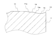
- FIG. 2 is an enlarged cross-sectional view in which a region including a first protrusion is enlarged in the Y1-Y1 cross section of the cutting insert shown in FIG.
- FIG. 6 is an enlarged cross-sectional view in which a region including a second protrusion is enlarged in the Y2-Y2 cross section of the cutting insert shown in FIG. 5. It is process drawing of the cutting method concerning one Embodiment of this invention. It is process drawing of the cutting method concerning one Embodiment of this invention. It is process drawing of the cutting method concerning one Embodiment of this invention.
- the cutting insert of one embodiment is explained in detail using a drawing.
- the drawings referred to below for convenience of explanation, among the constituent members of the embodiment, only the main members necessary for explaining the present invention are shown in a simplified manner. Therefore, the cutting insert of the present invention may include any component not shown in the drawings to which the present specification refers.
- the dimension of the member in each figure does not represent the dimension of an actual structural member, the dimension ratio of each member, etc. faithfully.
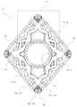
- the cutting insert 1 of the present embodiment includes an upper surface 3 and a lower surface 5 having a square shape when viewed in plan, specifically a rhombus shape. More specifically, the upper surface 3 and the lower surface 5 are not strictly square. Corners that are the intersections of the sides forming a quadrangle are corners that are curved.
- the side surface 7 has a flat portion located between the sides forming the quadrangle on the upper surface 3 and the lower surface 5 and a curved portion located between the curved portions on the upper surface 3 and the lower surface 5. is doing. Specifically, the side surface 7 has a flat first side surface 7a, a curved corner side surface 7b, and a flat second side surface 7c.
- the upper surface 3 and the lower surface 5 have substantially the same shape so as to overlap each other when seen in a plan view. Therefore, the four side surfaces 7 located between the upper surface 3 and the lower surface 5 are formed perpendicular to the upper surface 3 and the lower surface 5, respectively.
- the cutting insert 1 is formed in a polygonal column shape, specifically, a quadrangular column shape.
- a cutting edge 9 is formed at each intersection between the upper surface 3 and the side surface 7 and each intersection between the lower surface 5 and the side surface 7. That is, the cutting insert 1 according to the present embodiment is a so-called negative type cutting in which cutting edges 9 are formed not only at the intersection between the upper surface 3 and the side surface 7 but also at the intersection between the lower surface 5 and the side surface 7. Insert 1. Note that there is no problem even if the cutting insert 1 is a so-called positive type cutting insert 1 in which the cutting edge 9 is formed only at the intersection of the upper surface 3 and the side surface 7.
- the cutting insert 1 of the present embodiment is a negative type, and the lower surface 5 of the cutting insert 1 of the present embodiment has the same configuration as the upper surface 3 although not particularly shown.
- the negative cutting insert 1 can be used upside down. That is, when the lower surface 5 of the cutting insert 1 is mounted on the holder 103 as a seating surface, the cutting edge 9 formed at the intersection of the upper surface 3 and the side surface 7 of the cutting insert 1 is used for the cutting process. Can do.
- the upper surface 3 of the cutting insert 1 is mounted on the holder 103 with the upper surface 3 of the cutting insert 1 as a seating surface, the cutting blade 9 formed at the intersection of the lower surface 5 and the side surface 7 of the cutting insert 1 is used. It can be used for cutting.
- first cutting edge 9a is at the intersection of the upper surface 3 and the first side surface 7a
- corner cutting edge 9b is at the intersection of the upper surface 3 and the corner side surface 7b
- second cutting edges 9c are formed at the intersections with 7c, respectively.
- the cutting edge 9 in the present embodiment has a corner portion adjacent to the corner cutting edge 9b in the first cutting edge 9a and the second cutting edge 9c. As the distance from the portion 27 increases, the lower surface is inclined. Although the portion adjacent to the corner cutting edge 9b in the first cutting edge 9a and the second cutting edge 9c is used at the time of high cutting, this configuration can reduce the cutting resistance of this portion.
- the width in the longitudinal direction of the rhombic upper surface 3 in the cutting insert 1 of the present embodiment is set to about 15 to 25 mm, for example.
- the width in the direction perpendicular to the longitudinal direction is set to about 10 to 22 mm.
- the size of the rhombus-shaped lower surface 5 is set in accordance with the size of the upper surface 3 described above.
- the thickness of the cutting insert 1 is set to about 3 to 7 mm, for example.
- the thickness means the width in the vertical direction from the uppermost portion of the upper surface 3 to the lowermost portion of the lower surface 5 when the cutting insert 1 is viewed from the side.
- flat surfaces are formed on the upper end of the upper surface 3 and the lower end of the lower surface 5 as a seating surface when the holder 103 is mounted. The width in the vertical direction on these flat surfaces is the thickness of the cutting insert 1.
- Examples of the material of the cutting insert 1 include cemented carbide or cermet.
- the composition of the cemented carbide is, for example, WC—Co produced by adding cobalt (Co) powder to tungsten carbide (WC) and sintering, and WC—coating WC—Co with titanium carbide (TiC).
- WC—TiC—TaC—Co in which tantalum carbide (TaC) is added to TiC—Co or WC—TiC—Co.
- the cermet is a sintered composite material in which a metal is combined with a ceramic component, and specifically includes a titanium compound mainly composed of titanium carbide (TiC) or titanium nitride (TiN).
- the surface of the cutting insert 1 may be coated with a film using a chemical vapor deposition (CVD) method or a physical vapor deposition (PVD) method.
- CVD chemical vapor deposition
- PVD physical vapor deposition
- the composition of the coating include titanium carbide (TiC), titanium nitride (TiN), titanium carbonitride (TiCN), and alumina (Al 2 O 3 ).
- the upper surface 3 of the cutting insert 1 of the present embodiment has a main part 11, a land part 13, and a breaker groove 15.
- the main portion 11 has an upwardly convex shape and is positioned so as to surround a through hole 17 described later.
- a land portion 13 is formed on the periphery of the upper surface 3 so as to surround the main portion 11. That is, the cutting edge 9 is formed at the intersection of the land portion 13 and the side surface 7.
- a breaker groove 15 is formed between the main portion 11 and the land portion 13.
- the height of the main portion 11 and the land portion 13 from the lower surface 5 is higher than the height of the bottom surface of the breaker groove 15 from the lower surface 5. Further, the height of the main portion 11 from the lower surface 5 is higher than the height of the land portion 13 from the lower surface 5.
- the rake angle of the region along the cutting edge 9 in the breaker groove 15 is maximized in the vicinity of the corner portion 27 for the purpose of drawing chips in the high cutting region and promoting the curling of the chips and reducing the cutting resistance. ing. Further, the portion corresponding to the corner portion 27 and the portion away from the corner portion 27 have a relatively smaller angle than the above portion in order to maintain the strength.
- the above-mentioned “height from the lower surface 5" means the width of the up-down direction from this flat surface, when the lower surface 5 is a flat surface. Further, if the lower surface 5 is uneven as in the cutting insert 1 of the present embodiment, the “height from the lower surface 5” is a flat surface that functions as a seating surface when the holder 103 is mounted. It means the width in the vertical direction from the lower end surface.
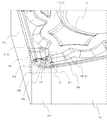
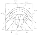
- the upper surface 3 includes a first projecting portion 19 projecting from the main portion 11 toward the corner portion 27 of the upper surface 3 and a pair of second projecting portions projecting from the first projecting portion 19 toward the periphery of the upper surface 3. Projecting portions 21, 23.
- the height of the first protrusion 19 and the second protrusions 21 and 23 from the lower surface 5 is lower than the height of the main portion 11 from the lower surface 5.
- the pair of second protrusions 21 and 23 are at least a tip 19a (hereinafter also simply referred to as a tip 19a) of the first protrusion 19 and a space between the tip of the first protrusion 19 and the corner 27. It is located so as to sandwich the area between them.
- the pair of second projecting portions 21 and 23 does not simply project from the first projecting portion 19 toward the periphery of the upper surface 3, but a pair of second projecting portions.
- Each of the upper ends of the projections 21 and 23 has a first feature that the projections 21 and 23 are separated from the first projection 19. That is, a recess 25 that is a depression is formed at the boundary between the first protrusion 19 and the second protrusions 21 and 23. More specifically, a recess 25 that opens between the first protrusion 19 and the second protrusions 21 and 23 and opens in a direction perpendicular to the direction in which the second protrusions 21 and 23 protrude. Is formed.
- a through-hole 17 penetrating from the center of the upper surface 3 to the center of the lower surface 5 is formed.
- the through hole 17 is provided for inserting a bolt 105 when the cutting insert 1 is screwed and fixed to the holder 103 of the cutting tool 101.
- a clamp structure may be employed instead of the above-described method by screwing and fixing.
- the main part 11 has a flat upper end surface.
- the upper end surface of the main portion 11 functions as a seating surface.
- the first protruding portion 19 protrudes from the main portion 11 toward the corner portion 27 of the upper surface 3.
- the pair of second protrusions 21 and 23 are positioned so as to sandwich the region between the tip of the first protrusion 19 and the corner 27.
- the pair of second protrusions 21 and 23 are positioned so as to sandwich a straight line connecting the tip of the first protrusion 19 and the corner 27.
- the pair of second protrusions 21 and 23 are positioned so as to be symmetric with respect to the straight line as a central axis.
- the 1st protrusion part 19 and the 2nd protrusion parts 21 and 23 each function as what is called a breaker of chip.
- Each of the upper ends of the pair of second protrusions 21 and 23 can be configured to be located at the same height as the upper end of the first protrusion 19.
- the height of the upper end of the first projecting portion 19, specifically, the height from the lower surface 5 is approximately the same as the height of the upper end of the second projecting portions 21 and 23, so that the chips can be bent more stably. Can be made.
- the chips are brought into contact with either of the second projecting portions 21 and 23 and the chips are directed to the rear end portion 19b of the first projecting portion 19, the chips are easily brought into contact with the rear end portion 19b smoothly. .
- the chips strongly come into contact with the rear end portion 19b of the first projecting portion 19, the chips are easily clogged starting from the rear end portion 19b.
- the chips come into strong contact with the front end 19a as well as the rear end 19b of the first protrusion 19, and the front end 19a can be damaged. There is sex. However, it is possible to reduce the possibility of the chips coming into strong contact with the front end portion 19a due to the smooth contact of the chips with the rear end portion 19b. As a result, the possibility that the front end portion 19a is damaged can be reduced.
- the upper end of the first protrusion 19 and the second protrusion 21 , 23 have the same height at the upper ends, it is possible to reduce variation in chip curvature in the first protrusion 19 and the second protrusions 21, 23. Therefore, it is possible to bend the chips stably.
- the tip surface 19 a of the first protrusion 19 has a flat surface shape that is inclined with respect to the lower surface 5, and the tip surface 11 a of the main portion 11 is inclined with respect to the lower surface 5. It is a concave curved surface shape.
- chips come into contact with the tip surface of the first protrusion 19 in addition to the side surfaces of the second protrusions 21 and 23.
- the tip of the first projecting portion 19 is a flat inclined surface in order to stably curve the chips that are relatively thin and easily deformed.
- chips are brought into contact with the tip surface of the main portion 11 during high-feed machining.
- the thickness of the chips is relatively large.
- the front end of the main portion 11 becomes a concave inclined surface. ing.
- a portion close to the cutting edge 9c is mainly used. Which of the corner cutting edge 9b close to the first cutting edge 9a or the corner cutting edge 9b close to the second cutting edge 9c is used is determined by the direction in which the work material 201 is brought into contact.
- the chips of the work material cut at this portion are the first of the second protrusions 21 and 23.
- the second protrusion 23 By contacting the second protrusion 23 that is relatively distant from the cutting edge 9a, it is deformed and divided.
- the second protruding portion 21 protrudes toward the boundary between the first cutting edge 9a and the corner cutting edge 9b, and the second protruding portion 23 is the second cutting edge. It protrudes toward the boundary between 9c and the corner cutting edge 9b, and the second feature is that the height of the tip 19a is lower than the height of the upper surfaces of the second protrusions 21 and 23.
- the second protrusions 21 and 23 are not simply arranged symmetrically with respect to the corner bisector, but the second protrusion 21 is the first cutting edge 9a. Projecting toward the boundary between the second cutting edge 9c and the corner cutting edge 9b.
- the second protrusion 23 is not directed toward the above-mentioned boundary, but the second protrusion 23 is directed toward the corner of the upper surface 3 from the boundary between the second cutting edge 9c and the corner cutting edge 9b, that is, at the corner.
- interval of the 2nd protrusion part 23 and the 1st cutting edge 9a can be narrowed.
- the angle formed by the projecting direction of the second projecting portion 23 and the first cutting edge 9a increases. Therefore, it becomes difficult to bring the chips into contact with the second projecting portion 23 and to bend them well, and the cutting performance of the chips is lowered.
- the cutting insert 1 of this embodiment since the 2nd protrusion part 23 protrudes toward said boundary, the angle which the direction which the 2nd protrusion part 23 protrudes, and the 1st cutting edge 9a make
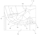
- the second protrusion 21 protrudes toward the boundary between the first cutting edge 9 a and the corner cutting edge 9 b” means that the tip of the second protrusion 21.
- a straight line that is parallel to the straight line X1 connecting the rear ends and that passes through at least a part of the second protrusion 21 is located on the boundary between the first cutting edge 9a and the corner cutting edge 9b.
- the boundary between the first cutting edge 9a and the corner cutting edge 9b is located between two two-dot chain lines that sandwich the straight line X1. Therefore, the straight line connecting the front end and the rear end of the second projecting portion 21 is not limited to being strictly located on the boundary.
- the second protrusions 21 and 23 are positioned so as to sandwich at least the tip 19a of the first protrusion 19 therebetween.
- the tip 19a of the first protrusion 19 protrudes toward the corner cutting edge 9b between the second protrusions 21 and 23.
- the chips of the work material cut at the portion near the first cutting edge 9a of the corner cutting edge 9b are first applied to the tip 19a of the first protrusion 19.
- the tip 19 a of the first protrusion 19 is located closer to the first cutting edge 9 a than the second protrusion 23. Thereby, chips can be brought into contact with the distal end portion 19a of the first projecting portion 19 at the time of cutting by low feed.
- the cutting insert 1 of the present embodiment can perform cutting well in each of the low feed processing and the high feed processing even when the radius of curvature of the corner is increased.
- the height of the tip 19a and the height of the upper surfaces of the second protrusions 21 and 23 can be evaluated by calculating the “height from the lower surface 5” as described above.
- the “upper surface” of the second protrusions 21 and 23 means the highest part of the second protrusions 21 and 23 from the lower surface 5, and it is not necessarily a flat surface. No. In other words, of the first protrusions 19, the height of the upper surface of the portion sandwiched between the second protrusions 21 and 23 is the highest position in the second protrusions 21 and 23. It is lower than the height of the upper end.
- the cutting insert 1 according to the present embodiment is favorably used for cutting with a wide feed amount in the low cutting process of cutting the work material 201 in the area of the corner cutting edge 9b.
- the cutting insert 1 of this embodiment is used favorably at the time of low cutting, it naturally does not impede use at the time of high cutting.
- the above description is for the case where the portion near the first cutting edge 9a in the corner cutting edge 9b is mainly used for cutting, but the portion near the second cutting edge 9c in the corner cutting edge 9b is mainly used.
- the role of the second protrusion 21 and the role of the second protrusion 23 are reversed.
- the first projecting portion 19 has a front end portion 19a sandwiched between the second projecting portions 21 and 23 and a portion located on the rear end side from the front end portion 19a.
- this portion is referred to as a rear end portion 19b for convenience.
- the upper surface of the tip 19a is a flat inclined surface.
- the upper surface of the rear end portion 19b is a concave curved inclined surface.
- the top surfaces of the front end portion 19a and the rear end portion 19b are inclined surfaces whose height decreases as they approach the corner cutting edge 9b.
- the tip 19a of the first protrusion 19 mainly functions when the chips are brought into contact with and deformed during low cutting and low feed processing.
- the thickness of the chip is small, so that the chip is easily curved by coming into contact with the tip 19a whose upper surface is a flat inclined surface.
- the cutting amount is large and the feeding amount is large, there is a possibility that the chips get over the front end portion 19a and come into contact with the rear end portion 19b of the first protruding portion 19.
- the upper surface of the rear end portion 19b is a concave curved inclined surface, when the chips advance along the inclined surface, the contact area between the chips and the rear end portion 19b is increased. Can do. Therefore, since it is possible to brake the chips stably, the chips can be divided efficiently.
- variety of the rear-end part 19b of the 1st protrusion part 19 in the direction orthogonal to the direction where the 1st protrusion part 19 protruded is toward the front end side from the rear end side. It is getting smaller gradually.
- the width of the tip 19a of the first protrusion 19 in the direction perpendicular to the direction in which the first protrusion 19 protrudes gradually increases from the rear end toward the tip. Since the width of the tip end portion 19a on the tip end side is relatively large, chips can be stably ridden on the upper surface of the tip end portion 19a during processing with a low depth of cut.
- tip part 19a is relatively small rather than the whole width
- the upper surface of the rear end portion 19b of the first projecting portion 19 is a concave curved surface as already shown. For this reason, when the chips are brought into contact with the rear end portion 19b, a larger load is easily applied from the chips to the rear end side than to the front end side in the upper surface of the rear end portion 19b.
- the width on the rear end side of the rear end portion 19b is relatively large, it is possible to increase the contact area with the chips on the rear end side of the rear end portion 19b to which the above-described relatively large load is easily applied. it can. Therefore, the load applied to the first protrusion 19 can be dispersed. As a result, the durability of the rear end portion 19b of the first projecting portion 19 can be improved.
- variety in the front end side of the rear-end part 19b is relatively small rather than the whole width
- tip part of the 2nd protrusion parts 21 and 23 protrudes in the direction where the 1st protrusion part 19 protruded rather than the front-end
- FIG. a straight line that is orthogonal to the direction in which the first protrusion 19 protrudes and that is in contact with the tip of the first protrusion 19 is defined as X3. Further, a straight line that is orthogonal to the direction in which the first projecting portion 19 projects and is in contact with the tips of the second projecting portions 21 and 23 is represented by X4.
- the straight line X4 is parallel to the straight line X3, and the straight line X4 is located closer to the corner 27, which is the direction in which the first protrusion 19 protrudes, than the straight line X3. Therefore, a recess is formed in a region surrounded by the corner cutting edge 9b, the first protrusion 19, and the second protrusions 21 and 23.
- the recess constitutes a part of the breaker groove 15. In the case where such a recess is formed, chips that come into contact with the second protrusion 23 are easily deformed in the recess.
- the second projecting portions 21 and 23 project linearly, respectively.
- projecting linearly means that, for example, in the case of the second projecting portion 23, the ridge lines connecting the front end and the rear end of the second projecting portion 23 are formed linearly, respectively. is doing. Therefore, the second protrusion 23 itself does not have to be linear, and as shown in FIGS. 6 and 7, a wide elliptical sphere at the center between the front end side and the rear end side, or a water drop It may be a shape.
- the upper surfaces of the second protrusions 21 and 23 in the cutting insert 1 of the present embodiment are convex curved surfaces, and the lower ends of the side surfaces are concave curved surfaces. Therefore, in the cross section that is perpendicular to the lower surface 5 and includes the second protrusion 23, the upper surface including the upper surface is indicated by a convex curve, and the lower surface continuous to the breaker groove 15 is indicated by a concave curve. It is.
- the chips come into contact with the surfaces of the second protrusions 21 and 23 across the tip 19a of the first protrusion 19.
- the chips that come into contact with the second protrusions 21 and 23 can be easily curled on the surface of the second protrusion 23 that has a concave curved surface on the lower end side that is continuous with the breaker groove 15. Can be made.
- the feed amount is further increased, and the second projecting portions 21 and 23 are moved to the rear end portion 19b of the first projecting portion 19. It is possible to smoothly advance the chips. Therefore, the chips can be stably deformed on the upper surface of the rear end portion 19b.
- the protruding direction of the second protruding portion 23 is substantially parallel to the second side surface 7c.
- the chips are stably curved by the second protrusion 23 when processing the feed amount in which the chips contact the second protrusion 23. be able to. Therefore, since it becomes easy to cut
- the protruding direction of the second protruding portion 21 is substantially parallel to the first side surface 7a.
- Example sizes of the first projecting portion 19 and the second projecting portions 21 and 23 are as follows.
- the length of the rear end portion 19b of the first projecting portion 19 shown in the projecting direction of the first projecting portion 19 (vertical direction in FIG. 5) is 0.4 to 1 mm, which is orthogonal to the above direction.
- the width of the rear end portion 19b indicated by the direction can be set to 0.3 to 0.6 mm.
- the length of the tip 19a of the first protrusion 19 shown in the direction in which the first protrusion 19 protrudes is 0.3 to 0.7 mm, and the direction perpendicular to the above direction.
- the width of the tip portion 19a shown by can be set to 0.4 to 0.7 mm.
- the length of each of the second protrusions 21 indicated by the direction in which the second protrusion 21 protrudes is 0.3 to 0.8 mm, and the length of the second protrusion 21 indicated by the direction orthogonal to the above-described direction.
- the width can be set to 0.3 to 0.6 mm.
- the length of each of the third protrusions 23 indicated by the direction in which the third protrusion 23 protrudes is 0.3 to 0.8 mm, and the length of the third protrusion 23 indicated by the direction orthogonal to the above-described direction.
- the width can be set to 0.3 to 0.6 mm.
- the cutting insert 1 of the present embodiment has a rhombic quadrilateral shape when viewed from above, but is not limited to such a form.
- the shape of the upper surface 3 in a plan view may be a polygonal shape such as a triangle, pentagon, hexagon, or octagon.
- the shape when viewed in plan is a quadrangular shape does not necessarily require a quadrangular shape, and is a configuration in which the main part of the outer periphery of the upper surface 3 is composed of four sides. May be partially curved.
- the cutting tool 101 of this embodiment includes a cutting insert 1 represented by the above embodiment and a holder 103 to which the cutting insert 1 is attached, as shown in FIGS.
- the holder 103 of this embodiment is rod-shaped and has an insert pocket in which the cutting insert 1 is mounted at one end.
- the cutting insert 1 is mounted so that the cutting edge 9 protrudes outside the outer periphery of the holder 103.
- the cutting insert 1 is fixed to the insert pocket by the bolt 105. That is, the bolt 105 is inserted into the through-hole 17 of the cutting insert 1, the tip of the bolt 105 is inserted into a screw hole (not shown) formed in the insert pocket, and the screw parts are screwed together to cut.
- the insert 1 is attached to the holder 103.
- steel, cast iron or the like can be used.
- steel having high toughness among these members it is preferable to use steel having high toughness among these members.
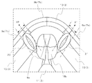
- the manufacturing method of this embodiment includes the following steps. That is, (1) As shown in FIG. 10, a process of relatively bringing the cutting tool 101 typified by the above embodiment close to the work material 201 in a state where the work material 201 is rotated, (2) As shown in FIG. 11, a step of bringing at least the corner cutting edge 13 out of the cutting edge 9 of the cutting tool 101 into contact with the rotating work material 201; (3) As shown in FIG. 12, the step of separating the cutting tool 101 from the work material 201; It has.
- the cutting insert 1 since the cutting insert 1 has the 1st protrusion part 19 and the 2nd protrusion parts 21 and 23 provided with said characteristic structure, it is wide. It is possible to cope with cutting of the feed amount.
- the work material 201 is rotated with the rotating shaft fixed, and the cutting tool 101 is brought closer.
- cutting is performed by bringing the cutting tool 101 into contact with the work material 201 while the work material 201 is rotated.
- the work material 201 is rotated with the rotating shaft fixed, and the cutting tool 101 is moved away.
- the work material 201 is rotated and the cutting tool 101 is moved in a state where the rotation shaft is fixed, but it is naturally limited to such a form. It is not a thing.
- the work material 201 may be brought close to the cutting tool 101 in the step (1).
- the work material 201 may be moved away from the cutting tool 101.
- the state in which the workpiece 201 is rotated and the corner cutting edge 9b of the cutting insert 1 is brought into contact with a different portion of the workpiece 201 may be repeated.
- the cutting insert 1 is rotated 180 degrees with respect to the central axis of the through hole 17 or turned upside down to use the unused corner cutting edge 9b. it can.
- representative examples of the material of the work material 201 include carbon steel, alloy steel, stainless steel, cast iron, and non-ferrous metal.
Landscapes
- Engineering & Computer Science (AREA)
- Mechanical Engineering (AREA)
- Cutting Tools, Boring Holders, And Turrets (AREA)
Abstract
Description
以下、一実施形態の切削インサートについて、図面を用いて詳細に説明する。但し、以下で参照する各図は、説明の便宜上、実施形態の構成部材のうち、本発明を説明するために必要な主要部材のみを簡略化して示したものである。従って、本発明の切削インサートは、本明細書が参照する各図に示されていない任意の構成部材を備え得る。また、各図中の部材の寸法は、実際の構成部材の寸法および各部材の寸法比率等を忠実に表したものではない。
次に、本発明の一実施形態の切削工具101について図面を用いて説明する。
次に、本発明の一実施形態の被削材201を切削することによる切削加工物の製造方法について図面を用いて説明する。
(1)図10に示すように、被削材201を回転させた状態で上記実施形態に代表される切削工具101を被削材201に相対的に近付ける工程と、
(2)図11に示すように、回転している被削材201に切削工具101の切刃9のうち少なくともコーナ切れ刃13を接触させる工程と、
(3)図12に示すように、切削工具101を被削材201から離す工程と、
を備えている。
3・・・上面
5・・・下面
7・・・側面
7a・・・第1側面
7b・・・コーナ側面
7c・・・第2側面
9・・・切刃
9a・・・第1切刃
9b・・・コーナ切刃
9c・・・第2切刃
11・・・主部
13・・・ランド部
15・・・ブレーカ溝
17・・・貫通孔
19・・・第1の突出部
19a・・・先端部
19b・・・後端部
21・・・第2の突出部
23・・・第3の突出部
25・・・凹部
27・・・角部
101・・・切削工具
103・・・ホルダ
105・・・ボルト
201・・・被削材
Claims (9)
- 上面、下面、ならびに前記上面および前記下面の間に位置する側面を有し、前記上面と前記側面との交線部に切刃が形成された多角柱形状の切削インサートであって、
前記上面が、平坦な上端面を有する凸形状の主部と、該主部から前記上面の角部に向かって突出した第1の突出部と、該第1の突出部の先端と前記角部との間の領域を間に挟むように前記第1の突出部から前記上面の周縁に向かってそれぞれ突出した一対の第2の突出部とを有し、
前記一対の第2の突出部の上端のそれぞれが前記第1の突出部から離れていることを特徴とする切削インサート。 - 前記一対の第2の突出部の上端の高さが、前記第1の突出部の上端の高さと同じであることを特徴とする請求項1に記載の切削インサート。
- 前記第1の突出部の先端が平坦な傾斜面であるとともに、前記主部の先端が凹形状の傾斜面であることを特徴とする請求項1に記載の切削インサート。
- 前記一対の第2の突出部の一方の突出する方向が、前記一対の第2の突出部の他方が突出する方向に位置する部分の前記切刃と平行であることを特徴とする請求項1に記載の切削インサート。
- 前記側面は、第1側面、コーナ側面および第2側面を順に有し、
前記切刃は、前記上面と前記第1側面との交線部に形成された第1切刃と、前記上面と前記コーナ側面との交線部に形成されたコーナ切刃と、前記上面と前記第2側面との交線部に形成された第2切刃とを有し、
前記一対の第2の突出部の一方が、前記第1切刃と前記コーナ切刃との境界に向かって突出しているとともに、前記一対の第2の突出部の他方が、前記第2切刃と前記コーナ切刃との境界に向かって突出しており、
前記第1の突出部の先端部の高さが、前記一対の第2の突出部の上面の高さよりも低いことを特徴とする請求項1に記載の切削インサート。 - 前記一対の第2の突出部の先端部が、前記第1の突出部の先端部よりも前記第1の突出部の突出した方向にそれぞれ突出していることを特徴とする請求項5に記載の切削インサート。
- 前記第2の突出部の上面が凸曲面状であることを特徴とする請求項5または6に記載の切削インサート。
- 請求項1~7のいずれか1つに記載の切削インサートと、
前記切削インサートが装着されたホルダとを具備した切削工具。 - 被削材を回転させる工程と、
回転している前記被削材に請求項8に記載の切削工具の前記切刃を接触させる工程と、
前記切削工具を前記被削材から離隔する工程とを備えた切削加工物の製造方法。
Priority Applications (3)
| Application Number | Priority Date | Filing Date | Title |
|---|---|---|---|
| CN201380011226.5A CN104136158B (zh) | 2012-02-29 | 2013-02-08 | 切削镶刀、切削工具以及切削加工物的制造方法 |
| JP2014502107A JP5844881B2 (ja) | 2012-02-29 | 2013-02-08 | 切削インサート、切削工具および切削加工物の製造方法 |
| US14/381,726 US9707625B2 (en) | 2012-02-29 | 2013-02-08 | Cutting insert, cutting tool, and method of manufacturing machined product |
Applications Claiming Priority (4)
| Application Number | Priority Date | Filing Date | Title |
|---|---|---|---|
| JP2012-042889 | 2012-02-29 | ||
| JP2012042889 | 2012-02-29 | ||
| JP2012-079342 | 2012-03-30 | ||
| JP2012079342 | 2012-03-30 |
Publications (1)
| Publication Number | Publication Date |
|---|---|
| WO2013129083A1 true WO2013129083A1 (ja) | 2013-09-06 |
Family
ID=49082285
Family Applications (1)
| Application Number | Title | Priority Date | Filing Date |
|---|---|---|---|
| PCT/JP2013/053073 Ceased WO2013129083A1 (ja) | 2012-02-29 | 2013-02-08 | 切削インサート、切削工具および切削加工物の製造方法 |
Country Status (4)
| Country | Link |
|---|---|
| US (1) | US9707625B2 (ja) |
| JP (1) | JP5844881B2 (ja) |
| CN (1) | CN104136158B (ja) |
| WO (1) | WO2013129083A1 (ja) |
Cited By (7)
| Publication number | Priority date | Publication date | Assignee | Title |
|---|---|---|---|---|
| CN103551613A (zh) * | 2013-11-08 | 2014-02-05 | 江苏切剀刀具有限公司 | 用于精加工的带有槽型的车削超硬刀片 |
| WO2015083716A1 (ja) * | 2013-12-03 | 2015-06-11 | 株式会社タンガロイ | 切削工具 |
| JP2016530116A (ja) * | 2013-09-16 | 2016-09-29 | イスカル リミテッド | 切り屑処理配置構成を含む仕上げ深さ旋削インサート |
| JP2019123071A (ja) * | 2018-01-12 | 2019-07-25 | 鼎鎮實業有限公司Deep Jet Industry Co .,Ltd. | カッター及びその製造方法 |
| JPWO2018159499A1 (ja) * | 2017-02-28 | 2019-11-21 | 京セラ株式会社 | 切削インサート、切削工具及び切削加工物の製造方法 |
| JPWO2021005951A1 (ja) * | 2019-07-08 | 2021-01-14 | ||
| JP7003388B1 (ja) | 2021-04-28 | 2022-01-20 | 株式会社タンガロイ | 切削工具 |
Families Citing this family (14)
| Publication number | Priority date | Publication date | Assignee | Title |
|---|---|---|---|---|
| DE102012004804C5 (de) | 2012-03-09 | 2019-03-14 | Kennametal Inc. | Stechschneidplatte sowie Stechschneidwerkzeug |
| DE102012111576B4 (de) * | 2012-11-29 | 2022-05-25 | Kennametal Inc. | Schneideinsatz mit Kühlmittelkanal und Schneidwerkzeug mit einem Werkzeughalter und einem solchen Schneideinsatz |
| US9579727B2 (en) | 2014-05-28 | 2017-02-28 | Kennametal Inc. | Cutting assembly with cutting insert having enhanced coolant delivery |
| CN107708902B (zh) * | 2015-06-23 | 2019-06-28 | 京瓷株式会社 | 切削镶刀、切削工具以及使用该切削工具的切削加工物的制造方法 |
| KR101838107B1 (ko) * | 2015-09-24 | 2018-03-14 | 한국야금 주식회사 | 절삭 인서트 |
| US11077502B2 (en) * | 2016-06-17 | 2021-08-03 | Kyocera Corporation | Cutting insert, cutting tool, and method of manufacturing machined product |
| US10710170B2 (en) * | 2016-08-03 | 2020-07-14 | Kyocera Corporation | Cutting insert, cutting tool, and method of manufacturing machined product |
| CN109475946B (zh) * | 2016-08-31 | 2020-06-26 | 住友电工硬质合金株式会社 | 切削刀具 |
| WO2019146645A1 (ja) * | 2018-01-23 | 2019-08-01 | 京セラ株式会社 | 切削インサート、切削工具及び切削加工物の製造方法 |
| US11446745B2 (en) * | 2018-09-27 | 2022-09-20 | Iscar, Ltd. | Turning insert having peninsula and island protrusions, and turning tool |
| DE102020117101A1 (de) * | 2020-06-29 | 2021-12-30 | Kennametal Inc. | Schneideinsatz und Zerspanungswerkzeug |
| KR102460409B1 (ko) * | 2021-05-06 | 2022-10-31 | 한국야금 주식회사 | 절삭인서트 및 이를 장착한 절삭공구 |
| CN117561134A (zh) * | 2021-07-30 | 2024-02-13 | 京瓷株式会社 | 涂层刀具及切削刀具 |
| DE102022127278A1 (de) * | 2022-10-18 | 2024-04-18 | Zcc Cutting Tools Europe Gmbh | Schneideinsatz |
Citations (4)
| Publication number | Priority date | Publication date | Assignee | Title |
|---|---|---|---|---|
| JP2007301669A (ja) * | 2006-05-11 | 2007-11-22 | Tungaloy Corp | スローアウェイチップ |
| JP2008213122A (ja) * | 2007-03-07 | 2008-09-18 | Mitsubishi Materials Corp | 切削インサート |
| JP2009208216A (ja) * | 2008-03-06 | 2009-09-17 | Hokkaido Sumiden Seimitsu Kk | 刃先交換式切削チップ |
| JP2010069614A (ja) * | 2008-08-22 | 2010-04-02 | Mitsubishi Materials Corp | 切削インサート |
Family Cites Families (29)
| Publication number | Priority date | Publication date | Assignee | Title |
|---|---|---|---|---|
| US4941780A (en) * | 1987-11-24 | 1990-07-17 | Sumitomo Electric Industries, Ltd. | Indexable cutting insert |
| EP0506078B1 (en) * | 1991-03-29 | 1996-12-11 | Mitsubishi Materials Corporation | Indexable cutter insert |
| DE4136417A1 (de) * | 1991-11-05 | 1993-05-06 | Krupp Widia Gmbh, 4300 Essen, De | Schneideinsatz |
| SE508452C2 (sv) * | 1992-07-02 | 1998-10-05 | Sandvik Ab | Skär för spånavskiljande bearbetning |
| DE4239236C2 (de) * | 1992-11-21 | 1997-06-26 | Widia Gmbh | Schneideinsatz |
| US5725334A (en) * | 1993-03-29 | 1998-03-10 | Widia Gmbh | Cutting insert |
| US5743681A (en) * | 1993-04-05 | 1998-04-28 | Sandvik Ab | Cutting insert with chip control protrusion on a chip surface |
| DE4314570C2 (de) * | 1993-05-05 | 2001-09-27 | Widia Gmbh | Vieleckiger Schneideinsatz |
| JPH09502397A (ja) * | 1993-09-13 | 1997-03-11 | ヴィディア ゲゼルシャフト ミット ベシュレンクテル ハフツング | 切削チップ |
| DE4336055A1 (de) * | 1993-09-13 | 1995-03-16 | Krupp Widia Gmbh | Schneideinsatz |
| DE4422312A1 (de) * | 1994-06-17 | 1995-12-21 | Krupp Widia Gmbh | Schneideinsatz |
| DE4437093A1 (de) * | 1994-10-17 | 1996-04-18 | Widia Gmbh | Vieleckiger Schneideinsatz |
| DE19528851A1 (de) * | 1995-08-05 | 1997-02-06 | Widia Gmbh | Polygonaler Schneideinsatz |
| JP3812473B2 (ja) * | 2001-11-20 | 2006-08-23 | 三菱マテリアル株式会社 | スローアウェイチップ |
| DE10346790A1 (de) * | 2003-10-08 | 2005-05-04 | Kennametal Widia Gmbh & Co Kg | Schneideinsatz |
| CZ296905B6 (cs) * | 2004-04-30 | 2006-07-12 | Pramet Tools, S. R. O. | Rezná desticka |
| EP1904254B1 (en) * | 2005-07-05 | 2013-12-25 | Seco Tools AB | A cutting insert for turning with a recess intended to give room for a cooling jet |
| CN101720264B (zh) * | 2007-06-26 | 2011-06-01 | 特固克有限会社 | 带有在其转角区域形成的突出部的切削刀片 |
| US8025465B2 (en) * | 2008-09-29 | 2011-09-27 | Kyocera Corporation | Cutting insert, cutting tool and cutting method using the same |
| SE533017C2 (sv) * | 2009-02-20 | 2010-06-08 | Seco Tools Ab | Skärverktyg och skär med fluidströmningsstrukturer |
| AT11676U1 (de) * | 2009-10-02 | 2011-03-15 | Ceratizit Austria Gmbh | Schneideinsatz für ein schneidwerkzeug |
| US8997610B2 (en) * | 2009-11-27 | 2015-04-07 | Kyocera Corporation | Cutting insert, cutting tool, and method of manufacturing machined product using the same |
| KR101142902B1 (ko) * | 2010-02-05 | 2012-05-10 | 대구텍 유한회사 | 절삭 인서트 |
| WO2011142297A1 (ja) * | 2010-05-11 | 2011-11-17 | 株式会社タンガロイ | 切削インサート |
| DE102010021730B4 (de) * | 2010-05-27 | 2018-12-13 | Kennametal Inc. | Wendeschneidplatte |
| JP5853613B2 (ja) * | 2010-11-15 | 2016-02-09 | 三菱マテリアル株式会社 | 切削インサート |
| US8967920B2 (en) * | 2011-09-13 | 2015-03-03 | Iscar, Ltd. | Cutting insert and chip-control arrangement therefor |
| US20150023744A1 (en) * | 2013-07-22 | 2015-01-22 | Kennametal Inc. | Cutting insert with chip dividers |
| AT14285U1 (de) * | 2013-12-02 | 2015-07-15 | Ceratizit Austria Gmbh | Schneideinsatz zur zerspanenden Drehbearbeitung |
-
2013
- 2013-02-08 US US14/381,726 patent/US9707625B2/en active Active
- 2013-02-08 CN CN201380011226.5A patent/CN104136158B/zh active Active
- 2013-02-08 WO PCT/JP2013/053073 patent/WO2013129083A1/ja not_active Ceased
- 2013-02-08 JP JP2014502107A patent/JP5844881B2/ja active Active
Patent Citations (4)
| Publication number | Priority date | Publication date | Assignee | Title |
|---|---|---|---|---|
| JP2007301669A (ja) * | 2006-05-11 | 2007-11-22 | Tungaloy Corp | スローアウェイチップ |
| JP2008213122A (ja) * | 2007-03-07 | 2008-09-18 | Mitsubishi Materials Corp | 切削インサート |
| JP2009208216A (ja) * | 2008-03-06 | 2009-09-17 | Hokkaido Sumiden Seimitsu Kk | 刃先交換式切削チップ |
| JP2010069614A (ja) * | 2008-08-22 | 2010-04-02 | Mitsubishi Materials Corp | 切削インサート |
Cited By (17)
| Publication number | Priority date | Publication date | Assignee | Title |
|---|---|---|---|---|
| JP2016530116A (ja) * | 2013-09-16 | 2016-09-29 | イスカル リミテッド | 切り屑処理配置構成を含む仕上げ深さ旋削インサート |
| CN103551613A (zh) * | 2013-11-08 | 2014-02-05 | 江苏切剀刀具有限公司 | 用于精加工的带有槽型的车削超硬刀片 |
| WO2015083716A1 (ja) * | 2013-12-03 | 2015-06-11 | 株式会社タンガロイ | 切削工具 |
| US20160214180A1 (en) * | 2013-12-03 | 2016-07-28 | Tungaloy Corporation | Cutting tool having breaker wall surfaces separated by a convex portion |
| CN106170355A (zh) * | 2013-12-03 | 2016-11-30 | 株式会社钨钛合金 | 切削工具 |
| JPWO2015083716A1 (ja) * | 2013-12-03 | 2017-03-16 | 株式会社タンガロイ | 切削工具 |
| CN106170355B (zh) * | 2013-12-03 | 2018-01-09 | 株式会社泰珂洛 | 切削工具 |
| US10086436B2 (en) * | 2013-12-03 | 2018-10-02 | Tungaloy Corporation | Cutting tool having breaker wall surfaces separated by a convex portion |
| JP7017553B2 (ja) | 2017-02-28 | 2022-02-08 | 京セラ株式会社 | 切削インサート、切削工具及び切削加工物の製造方法 |
| JPWO2018159499A1 (ja) * | 2017-02-28 | 2019-11-21 | 京セラ株式会社 | 切削インサート、切削工具及び切削加工物の製造方法 |
| JP2019123071A (ja) * | 2018-01-12 | 2019-07-25 | 鼎鎮實業有限公司Deep Jet Industry Co .,Ltd. | カッター及びその製造方法 |
| WO2021005951A1 (ja) * | 2019-07-08 | 2021-01-14 | 京セラ株式会社 | 切削インサート、切削工具及び切削加工物の製造方法 |
| JPWO2021005951A1 (ja) * | 2019-07-08 | 2021-01-14 | ||
| JP7325510B2 (ja) | 2019-07-08 | 2023-08-14 | 京セラ株式会社 | 切削インサート、切削工具及び切削加工物の製造方法 |
| US12157173B2 (en) | 2019-07-08 | 2024-12-03 | Kyocera Corporation | Cutting insert, cutting tool, and method for manufacturing machined product |
| JP7003388B1 (ja) | 2021-04-28 | 2022-01-20 | 株式会社タンガロイ | 切削工具 |
| JP2022170020A (ja) * | 2021-04-28 | 2022-11-10 | 株式会社タンガロイ | 切削工具 |
Also Published As
| Publication number | Publication date |
|---|---|
| JPWO2013129083A1 (ja) | 2015-07-30 |
| CN104136158A (zh) | 2014-11-05 |
| CN104136158B (zh) | 2017-03-01 |
| JP5844881B2 (ja) | 2016-01-20 |
| US9707625B2 (en) | 2017-07-18 |
| US20150075338A1 (en) | 2015-03-19 |
Similar Documents
| Publication | Publication Date | Title |
|---|---|---|
| JP5844881B2 (ja) | 切削インサート、切削工具および切削加工物の製造方法 | |
| JP6356781B2 (ja) | 切削インサート、切削工具及び切削加工物の製造方法 | |
| JP5606636B2 (ja) | 切削インサート、切削工具および切削加工物の製造方法 | |
| JP6005838B2 (ja) | 切削インサート、切削工具および切削加工物の製造方法 | |
| JP5438771B2 (ja) | 切削インサートおよび切削工具、並びにそれを用いた切削加工物の製造方法 | |
| JP6612900B2 (ja) | インサート、切削工具及び切削加工物の製造方法 | |
| JP6190039B2 (ja) | 切削インサート、切削工具及び切削加工物の製造方法 | |
| JP6194013B2 (ja) | 切削インサート、切削工具及び被削加工物の製造方法 | |
| JP6730442B2 (ja) | 切削インサート、切削工具及び切削加工物の製造方法 | |
| JP6272345B2 (ja) | 切削インサート及び切削工具、並びにそれらを用いた切削加工物の製造方法 | |
| WO2015178488A1 (ja) | 切削インサート、切削工具及び切削加工物の製造方法 | |
| WO2018155705A1 (ja) | 切削インサート、切削工具及び切削加工物の製造方法 | |
| WO2014017623A1 (ja) | 切削インサートおよび切削工具、ならびにそれらを用いた切削加工物の製造方法 | |
| JP5926366B2 (ja) | 切削インサート、切削工具および切削加工物の製造方法 | |
| WO2018012463A1 (ja) | 切削インサート、切削工具及び切削加工物の製造方法 | |
| JP5081229B2 (ja) | 切削インサートおよび切削工具、並びにそれを用いた被削材の切削方法 | |
| JPWO2017090770A1 (ja) | 切削インサート、切削工具及び切削加工物の製造方法 | |
| WO2018159499A1 (ja) | 切削インサート、切削工具及び切削加工物の製造方法 | |
| WO2014084252A1 (ja) | 切削インサート、切削工具および切削加工物の製造方法 | |
| WO2019004030A1 (ja) | 切削インサート、切削工具及び切削加工物の製造方法 | |
| JP6352639B2 (ja) | 切削インサート、切削工具および切削加工物の製造方法 | |
| WO2021005951A1 (ja) | 切削インサート、切削工具及び切削加工物の製造方法 | |
| JP6282921B2 (ja) | 切削インサート、切削工具および切削加工物の製造方法 | |
| WO2018043373A1 (ja) | 切削インサート、切削工具及び切削加工物の製造方法 | |
| JP6363355B2 (ja) | 切削インサート、切削工具および被削加工物の製造方法 |
Legal Events
| Date | Code | Title | Description |
|---|---|---|---|
| 121 | Ep: the epo has been informed by wipo that ep was designated in this application |
Ref document number: 13754114 Country of ref document: EP Kind code of ref document: A1 |
|
| ENP | Entry into the national phase |
Ref document number: 2014502107 Country of ref document: JP Kind code of ref document: A |
|
| WWE | Wipo information: entry into national phase |
Ref document number: 14381726 Country of ref document: US |
|
| NENP | Non-entry into the national phase |
Ref country code: DE |
|
| 122 | Ep: pct application non-entry in european phase |
Ref document number: 13754114 Country of ref document: EP Kind code of ref document: A1 |