WO2013129131A1 - Boîte de raccordement électrique - Google Patents
Boîte de raccordement électrique Download PDFInfo
- Publication number
- WO2013129131A1 WO2013129131A1 PCT/JP2013/053642 JP2013053642W WO2013129131A1 WO 2013129131 A1 WO2013129131 A1 WO 2013129131A1 JP 2013053642 W JP2013053642 W JP 2013053642W WO 2013129131 A1 WO2013129131 A1 WO 2013129131A1
- Authority
- WO
- WIPO (PCT)
- Prior art keywords
- case
- cover
- plate portion
- connection box
- peripheral wall
- Prior art date
- Legal status (The legal status is an assumption and is not a legal conclusion. Google has not performed a legal analysis and makes no representation as to the accuracy of the status listed.)
- Ceased
Links
Images



Classifications
-
- B—PERFORMING OPERATIONS; TRANSPORTING
- B60—VEHICLES IN GENERAL
- B60R—VEHICLES, VEHICLE FITTINGS, OR VEHICLE PARTS, NOT OTHERWISE PROVIDED FOR
- B60R16/00—Electric or fluid circuits specially adapted for vehicles and not otherwise provided for; Arrangement of elements of electric or fluid circuits specially adapted for vehicles and not otherwise provided for
- B60R16/02—Electric or fluid circuits specially adapted for vehicles and not otherwise provided for; Arrangement of elements of electric or fluid circuits specially adapted for vehicles and not otherwise provided for electric constitutive elements
- B60R16/023—Electric or fluid circuits specially adapted for vehicles and not otherwise provided for; Arrangement of elements of electric or fluid circuits specially adapted for vehicles and not otherwise provided for electric constitutive elements for transmission of signals between vehicle parts or subsystems
- B60R16/0238—Electrical distribution centers
-
- H—ELECTRICITY
- H02—GENERATION; CONVERSION OR DISTRIBUTION OF ELECTRIC POWER
- H02G—INSTALLATION OF ELECTRIC CABLES OR LINES, OR OF COMBINED OPTICAL AND ELECTRIC CABLES OR LINES
- H02G3/00—Installations of electric cables or lines or protective tubing therefor in or on buildings, equivalent structures or vehicles
- H02G3/02—Details
- H02G3/08—Distribution boxes; Connection or junction boxes
- H02G3/086—Assembled boxes
-
- H—ELECTRICITY
- H02—GENERATION; CONVERSION OR DISTRIBUTION OF ELECTRIC POWER
- H02G—INSTALLATION OF ELECTRIC CABLES OR LINES, OR OF COMBINED OPTICAL AND ELECTRIC CABLES OR LINES
- H02G3/00—Installations of electric cables or lines or protective tubing therefor in or on buildings, equivalent structures or vehicles
- H02G3/02—Details
- H02G3/08—Distribution boxes; Connection or junction boxes
- H02G3/16—Distribution boxes; Connection or junction boxes structurally associated with support for line-connecting terminals within the box
-
- H—ELECTRICITY
- H05—ELECTRIC TECHNIQUES NOT OTHERWISE PROVIDED FOR
- H05K—PRINTED CIRCUITS; CASINGS OR CONSTRUCTIONAL DETAILS OF ELECTRIC APPARATUS; MANUFACTURE OF ASSEMBLAGES OF ELECTRICAL COMPONENTS
- H05K5/00—Casings, cabinets or drawers for electric apparatus
- H05K5/0026—Casings, cabinets or drawers for electric apparatus provided with connectors and printed circuit boards [PCB], e.g. automotive electronic control units
- H05K5/0047—Casings, cabinets or drawers for electric apparatus provided with connectors and printed circuit boards [PCB], e.g. automotive electronic control units having a two-part housing enclosing a PCB
- H05K5/0056—Casings, cabinets or drawers for electric apparatus provided with connectors and printed circuit boards [PCB], e.g. automotive electronic control units having a two-part housing enclosing a PCB characterized by features for protecting electronic components against vibration and moisture, e.g. potting, holders for relatively large capacitors
-
- H—ELECTRICITY
- H05—ELECTRIC TECHNIQUES NOT OTHERWISE PROVIDED FOR
- H05K—PRINTED CIRCUITS; CASINGS OR CONSTRUCTIONAL DETAILS OF ELECTRIC APPARATUS; MANUFACTURE OF ASSEMBLAGES OF ELECTRICAL COMPONENTS
- H05K5/00—Casings, cabinets or drawers for electric apparatus
- H05K5/0026—Casings, cabinets or drawers for electric apparatus provided with connectors and printed circuit boards [PCB], e.g. automotive electronic control units
- H05K5/0047—Casings, cabinets or drawers for electric apparatus provided with connectors and printed circuit boards [PCB], e.g. automotive electronic control units having a two-part housing enclosing a PCB
- H05K5/006—Casings, cabinets or drawers for electric apparatus provided with connectors and printed circuit boards [PCB], e.g. automotive electronic control units having a two-part housing enclosing a PCB characterized by features for holding the PCB within the housing
-
- H—ELECTRICITY
- H05—ELECTRIC TECHNIQUES NOT OTHERWISE PROVIDED FOR
- H05K—PRINTED CIRCUITS; CASINGS OR CONSTRUCTIONAL DETAILS OF ELECTRIC APPARATUS; MANUFACTURE OF ASSEMBLAGES OF ELECTRICAL COMPONENTS
- H05K5/00—Casings, cabinets or drawers for electric apparatus
- H05K5/10—Casings, cabinets or drawers for electric apparatus comprising several parts forming a closed casing
- H05K5/15—Casings, cabinets or drawers for electric apparatus comprising several parts forming a closed casing assembled by resilient members
Definitions
- the present invention relates to an electrical connection box.
- the present invention has been completed based on the above circumstances, and it is possible to reduce the cost of the electric connection box provided with a water stop structure that prevents water from entering the inside of the case and adhering to the circuit assembly. Intended to be provided.
- a case including a bottom plate portion and a case side peripheral wall portion erected from a peripheral edge of the bottom plate portion, and a case having an opening portion opened laterally, and a circuit component housed inside the case.
- the projection length of the cover-side upper wall positioned on the upper side of the cover-side peripheral wall in a state where the electric connection box is used is extended outward from the outer surface of the bottom plate. It is considered to be the length to be released.
- the cover-side upper wall plays a role of a weir, it is possible to suppress water from entering the gap between the case-side peripheral wall and the cover-side peripheral wall and entering inside.
- the electrical connection box of the present invention is more preferably provided with the following configuration in addition to the above configuration.
- the area on the opening side protrudes outward more than the area on the bottom plate side. It is preferable that a level difference be provided.
- an inclined surface which is lowered toward the bottom plate portion side is provided on the upper surface of the region on the bottom plate portion side.
- the water that has entered the gap between the cover-side upper wall and the case-side upper wall is more easily discharged to the outside. Therefore, water can be more reliably prevented from entering the gap between the case side peripheral wall portion and the cover side peripheral wall portion and entering the inside.
- the cover protrudes from the lid plate toward the case and is disposed at an inner position relative to the case-side upper wall, and the circuit configuration It is preferable to have a waterproof wall that projects above the body.
- the above water stop structure can be realized with a relatively small cost increase as compared with the case structure which has not been coped with. For this reason, the electric connection box provided with the water stop structure can be provided at low cost.
- an electric connection box provided with a water stop structure that suppresses water from entering the inside of the case and adhering to the circuit structure.
- FIG. 1 is a perspective view of a case in the embodiment.
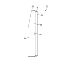
- FIG. 2 is a side view of the case in the embodiment.
- FIG. 3 is a perspective view showing a state in which the case and the cover in the embodiment are assembled.
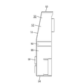
- FIG. 4 is a side view of the electrical connection box in the embodiment.
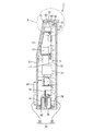
- FIG. 5 is a cross-sectional view of the electrical connection box in the embodiment.
- FIG. 6 is an enlarged view within the circle R of FIG.
- the electric connection box 1 of the present embodiment is used by being installed in a vehicle compartment of a vehicle, and includes a circuit structure 10 and a casing 20 that accommodates the circuit structure 10.
- the circuit structure 10 includes a circuit board 11 provided with a conductor circuit (not shown), and an electronic component 12 mounted (mounted) on the surface (mounting surface 17) of the circuit board 11.
- the electronic component 12 is not mounted on the back surface (non-mounting surface 18) of the circuit board 11.
- some of the electronic components 12 are covered with a metal shield shell 13.
- An electronic component that generates radiation noise is disposed in the upper approximately one third area on the mounting surface 17 of the circuit board 11, and an electronic component that does not generate radiation noise is disposed below the electronic component. Covers the upper area of about one third on the mounting surface 17 of the circuit board 11.
- a connector fitting portion 14 capable of fitting a mating connector connected to a power source or an on-vehicle electrical component is formed to open at the lower side. Inside the connector fitting portion 14, a connection terminal 15 electrically connected to a conductor circuit provided on the circuit board 11 is exposed. Further, in another region in the lower portion of the surface of the circuit board 11, a fuse terminal (not shown) electrically connected to the conductor circuit is disposed.
- the circuit structure 10 is housed inside the casing 20 in the vertical orientation, that is, the direction in which the surface direction of the circuit board 11 is the vertical direction.
- the casing 20 is made of synthetic resin and includes a case 30 for housing the circuit assembly 10 and a cover 50 assembled so as to close the opening 41 of the case 30.
- the case 30 is formed in the shape of a flat box whose side is open, and the circuit assembly 10 has the mounting surface 17 side (the side on which the electronic component 12 is mounted) in the case 30 in the opening 41 side. To be accommodated towards.
- the case 30 includes a bottom plate portion 31 formed in a rectangular shape that is slightly larger than the circuit assembly 10, and a case-side peripheral wall portion 32 erected on the periphery of the bottom plate portion 31.
- the case-side peripheral wall portion 32 is a first upper plate portion 33 (corresponding to the case-side upper wall portion) positioned on the upper side in a state where the electrical connection box 1 is disposed in the vehicle and used. 1 lower plate portion 34, and first side plate portions 35, 35 positioned on both left and right sides.
- the entire width of the first upper plate portion 33 and the first side plate portions 35, 35 and the portion of the first lower plate portion 34 excluding the formation position of the case-side connector opening 38 (described later)
- a step is attached. That is, the entire width of the first upper plate portion 33 and the first side plate portions 35 and 35 and the portion of the first lower plate portion 34 excluding the formation position of the case-side connector opening 38 are front side from the periphery of the bottom plate portion 31 After being extended toward the opening 41), the extension is further extended outward from the extension end, and is further extended to the front side from the extension end.
- the side area is stepped so as to project outward beyond the area on the bottom plate portion 31 side.
- the upper surface of the lower portion (the step on the side of the bottom plate portion 31) is a first inclined surface 36 (corresponding to the inclined surface) which descends toward the bottom plate portion 31 over the entire width. ing.
- a plurality of support protrusions 37 for protruding the circuit structure 10 for supporting the circuit structure 10 with a gap therebetween are provided on the inner side surface of the bottom plate portion 31, a plurality of support protrusions 37 for protruding the circuit structure 10 for supporting the circuit structure 10 with a gap therebetween are provided.
- the support projection 37 is lower than the height of the step surface of the case side peripheral wall portion 32 from the bottom plate portion 31 by the thickness of the circuit board 11, and the circuit structure 10 has the height of the step surface and the circuit board 11 is accommodated in the inside of case 30 in the state which substantially corresponds with the height of 11 surfaces.
- a case-side connector opening 38 for forming the connector fitting portion 14 of the circuit assembly 10 facing the outside is formed.
- the case-side connector opening 38 is formed by cutting out a portion of the first lower plate portion 34 that matches the connector fitting portion 14 of the circuit structure 10 from the edge on the opening 41 side to a certain depth. It is formed. Further, in the first lower plate portion 34, the water entering the inside of the case 30 is discharged in the region between the joining position with the bottom plate portion 31 and the portion where the case-side connector opening 38 is formed.
- a water draining hole 39 is provided to penetrate in the vertical direction.
- a lock projection 40 for locking the cover 50 is provided on the outer side surfaces of the first upper plate portion 33, the first lower plate portion 34, and the first side plate portions 35.
- the cover 50 is assembled to the case 30 from the surface side so as to close the opening 41 thereof.
- the cover 50 is in the form of a flat box whose rear surface side is open, and is a substantially rectangular plate-like lid plate 51 larger than the bottom plate 31 of the case 30 and a rim of the lid plate 51 And a cover side peripheral wall 52 provided.
- the cover side peripheral wall portion 52 is formed in a rectangular frame shape that is one size larger than the case side peripheral wall portion 32, and in the state where the case 30 and the cover 50 are assembled, the cover side peripheral wall portion 52 is of the case side peripheral wall portion 32.
- the outer periphery is covered.
- the cover side peripheral wall portion 52 is positioned on the lower side of the second upper plate portion 53 (corresponding to the cover side upper wall portion) positioned on the upper side in a state where the electrical connection box 1 is disposed in the vehicle and used.
- a second lower plate portion 54 and second side plate portions 55 located on both left and right sides are provided.
- the protruding length of the second upper plate portion 53 in the cover side peripheral wall portion 52 is a length such that the protruding end protrudes slightly outward from the outer surface of the bottom plate portion 31 in a state where the cover 50 is assembled with the case 30.
- the protruding lengths of the second lower plate portion 54 and the second side plate portions 55 are such that the position of the protruding end substantially matches the outer surface of the bottom plate portion 31 in the state where the cover 50 is assembled with the case 30. It is supposed to be.
- a third upper plate portion 56 protrudes from the inner side surface of the lid plate portion 51.
- the third upper plate portion 56 is erected on the inner side (lower side) with respect to the second upper plate portion 53 with a gap sufficient to receive the first upper plate portion 33 of the case side peripheral wall portion 32. It is done.
- the first upper plate portion 33 can be received between the second upper plate portion 53 and the third upper plate portion 56.
- the third upper plate portion 56 is positioned slightly above the upper end of the circuit assembly 10, and the projecting length of the third upper plate portion 56 is a circuit at the position of the projecting end when the circuit assembly 10 is accommodated in the casing 20.
- the length is located on the bottom plate portion 31 side of the non-mounting surface 18 of the substrate 11 and on the side of the lid plate portion 51 slightly spaced from the inner side surface of the bottom plate portion 31 of the case 30.
- a region extending from the protruding end to a position slightly closer to the cover plate portion 51 is a second inclined surface 57 which is lowered toward the protruding end side (bottom plate portion 31 side) over the entire width. It is assumed.
- a fuse mounting portion 58 capable of mounting a fuse is formed to open on the surface side. Inside the fuse mounting portion 58, a fuse provided in the circuit assembly 10 The terminal is facing. On the inner side surfaces of the second upper plate portion 53, the second lower plate portion 54, and the second side plate portions 55, 55, a plurality of lock receiving portions 59 engaging with the lock protrusions 40 of the case 30 are provided. .
- a cover-side connector opening 60 is formed in the second lower plate 54 at a position aligned with the case-side connector opening 38.
- the cover-side connector opening 60 is formed by cutting out a portion of the second lower plate 54 that matches the connector fitting portion 14 of the circuit assembly 10 to a certain depth from the edge on the opening side. It is done.
- the connector fitting portion 14 of the circuit assembly 10 is exposed to the outside from the cover-side connector opening 60 through the case-side connector opening 38.
- the water draining hole 39 formed in the first lower plate portion 34 also faces the outside from the cover-side connector opening 60.
- the circuit assembly 10 is mounted on the case 30 such that the mounting surface 17 (the surface on which the electronic component 12 is mounted) faces the opening 41 of the case 30 and the non-mounting surface 18 faces the bottom plate 31.
- the circuit assembly 10 is placed on the support projection 37, and a gap serving as a water passage is secured between the non-mounting surface 18 of the circuit assembly 10 and the inner side surface of the bottom plate 31.
- the cover 50 is assembled from the opening side of the case 30.
- the first upper plate portion 33 of the case 30 gets in between the second upper plate portion 53 of the cover 50 and the third upper plate portion 56.
- the case 30 and the cover 50 are engaged with each other by the engagement of the lock projection 40 and the lock receiving portion 59.
- the electric connection box 1 after assembly is a circuit in which the first upper plate portion 33, the second upper plate portion 53 and the third upper plate portion 56 face upward at a predetermined position in the vehicle, for example, and the inside is accommodated.
- the structure 10 is installed and used in the vehicle interior of the vehicle in a posture of being placed vertically.
- the electric connection box 1 is installed in a vehicle compartment of a vehicle, that is, basically at a place where rain, washing water and the like at the time of washing of the vehicle can be avoided. It is assumed that a small amount of water may be splashed by spilling water.
- the electrical connection box 1 of the present embodiment includes a bottom plate portion 31 and a case-side peripheral wall portion 32 erected from the peripheral edge of the bottom plate portion 31, and a case 30 that opens laterally;
- a cover plate 51, and a cover 50 having a cover side peripheral wall 52 which is erected from the peripheral edge of the cover plate 51 and covers the periphery of the case side peripheral wall 32;
- the protruding length of the second upper plate portion 53 in the cover side peripheral wall portion 52 is a length slightly protruding outward from the outer side surface of the bottom plate portion 31.
- the second upper plate portion 53 plays a role of a weir, and most of the water that has been applied to the electrical connection box 1 enters through the gap between the case side peripheral wall 32 and the cover side peripheral wall 52 Without falling down. Thereby, it can suppress that water enters inside from the crevice between case side peripheral wall part 32 and cover side peripheral wall part 52.
- the region on the opening 41 side protrudes outward more than the region on the bottom plate 31 side. There is a level difference.
- the upper surface of the lower portion (the step on the bottom plate portion 31 side) is a first inclined surface 36 which is lowered toward the bottom plate portion 31 side.
- the water that has entered the gap between the second upper plate portion 53 of the cover 50 and the first upper plate portion 33 of the case 30 flows to the bottom plate portion 31 side according to the inclination of the first inclined surface 36 , It becomes easy to be discharged outside. Therefore, it is possible to more reliably prevent water from entering the gap between the second upper plate portion 53 and the first upper plate portion 33 of the case 30 and entering the inside.
- the cover 50 projects from the cover plate 51 toward the case 30 and is disposed at an inner side (lower side) than the first upper plate 33 in a state of being assembled with the case 30, and a circuit structure A third upper plate portion 56 projecting above 10 is provided.
- the above-described water stop structure can be realized with a relatively small cost increase as compared with the case structure not yet coped with. For this reason, the electrical connection box 1 provided with the water stop structure can be provided at low cost.
- the step is provided on substantially the entire circumference of the case side peripheral wall portion 32 except for the position where the case side connector opening 38 is formed. It is sufficient if at least the electrical connection box is installed and provided in the first upper plate portion positioned on the upper side in the state of being used.
- the entire upper surface of the lower portion (the step on the bottom plate portion 31 side) is the first inclined surface 36 which is lowered toward the bottom plate portion 31 side.
- the surface may be provided only in a partial region near the projecting end on the upper surface of the case-side upper wall portion.
- the 1st inclined surface 36 is provided over the full width of the 1st upper board part 33, you may provide only a part of width direction.
Landscapes
- Engineering & Computer Science (AREA)
- Microelectronics & Electronic Packaging (AREA)
- Architecture (AREA)
- Civil Engineering (AREA)
- Structural Engineering (AREA)
- Mechanical Engineering (AREA)
- Casings For Electric Apparatus (AREA)
- Connection Or Junction Boxes (AREA)
Priority Applications (3)
| Application Number | Priority Date | Filing Date | Title |
|---|---|---|---|
| US14/377,216 US9204562B2 (en) | 2012-02-27 | 2013-02-15 | Electrical junction box |
| DE112013001161.1T DE112013001161T5 (de) | 2012-02-27 | 2013-02-15 | Elektrische Abzweigdose |
| CN201380011035.9A CN104137364B (zh) | 2012-02-27 | 2013-02-15 | 电连接箱 |
Applications Claiming Priority (2)
| Application Number | Priority Date | Filing Date | Title |
|---|---|---|---|
| JP2012-039816 | 2012-02-27 | ||
| JP2012039816A JP5930287B2 (ja) | 2012-02-27 | 2012-02-27 | 電気接続箱 |
Publications (1)
| Publication Number | Publication Date |
|---|---|
| WO2013129131A1 true WO2013129131A1 (fr) | 2013-09-06 |
Family
ID=49082333
Family Applications (1)
| Application Number | Title | Priority Date | Filing Date |
|---|---|---|---|
| PCT/JP2013/053642 Ceased WO2013129131A1 (fr) | 2012-02-27 | 2013-02-15 | Boîte de raccordement électrique |
Country Status (5)
| Country | Link |
|---|---|
| US (1) | US9204562B2 (fr) |
| JP (1) | JP5930287B2 (fr) |
| CN (1) | CN104137364B (fr) |
| DE (1) | DE112013001161T5 (fr) |
| WO (1) | WO2013129131A1 (fr) |
Families Citing this family (11)
| Publication number | Priority date | Publication date | Assignee | Title |
|---|---|---|---|---|
| JP5831757B2 (ja) * | 2012-02-27 | 2015-12-09 | 株式会社オートネットワーク技術研究所 | 電気接続箱 |
| JP6330686B2 (ja) * | 2015-02-18 | 2018-05-30 | 株式会社オートネットワーク技術研究所 | 基板ユニット |
| JP6372471B2 (ja) * | 2015-10-26 | 2018-08-15 | 住友電装株式会社 | 電気接続箱 |
| JP6642825B2 (ja) * | 2016-01-08 | 2020-02-12 | 住友電装株式会社 | 光ビーコン車載機 |
| JP6757150B2 (ja) | 2016-03-17 | 2020-09-16 | 株式会社神戸製鋼所 | 積層型流体加温器及び積層型流体加温器による流体の加温方法 |
| JP6673082B2 (ja) * | 2016-07-29 | 2020-03-25 | 住友電装株式会社 | 電気機器、及び電気機器システム |
| US11026340B2 (en) | 2016-11-11 | 2021-06-01 | Veoneer Sweden Ab | Passenger protection control device |
| CN112399759B (zh) * | 2019-08-13 | 2022-05-06 | 本田技研工业株式会社 | 基板收容箱 |
| JP7264002B2 (ja) * | 2019-09-30 | 2023-04-25 | 住友電装株式会社 | 電気接続箱 |
| US11462895B2 (en) * | 2020-04-09 | 2022-10-04 | Sumitomo Wiring Systems, Ltd. | Junction box with jump start terminal and water mitigation features |
| JP7529528B2 (ja) * | 2020-10-20 | 2024-08-06 | 株式会社デンソーテン | 電子機器 |
Citations (5)
| Publication number | Priority date | Publication date | Assignee | Title |
|---|---|---|---|---|
| JPS6359383U (fr) * | 1986-10-06 | 1988-04-20 | ||
| JPH0381682U (fr) * | 1989-12-13 | 1991-08-21 | ||
| JP2006351905A (ja) * | 2005-06-17 | 2006-12-28 | Oi Electric Co Ltd | 防水ケース |
| JP2007027395A (ja) * | 2005-07-15 | 2007-02-01 | Dx Antenna Co Ltd | 電子機器の収容ケースおよび増幅器 |
| JP2009111193A (ja) * | 2007-10-30 | 2009-05-21 | Kyocera Corp | 屋外設置型電子機器収納箱の防水構造 |
Family Cites Families (16)
| Publication number | Priority date | Publication date | Assignee | Title |
|---|---|---|---|---|
| JP4561520B2 (ja) | 2004-07-31 | 2010-10-13 | 住友電装株式会社 | 電気接続箱 |
| US7179990B2 (en) * | 2004-07-31 | 2007-02-20 | Sumitomo Wiring Systems, Ltd. | Electric junction box |
| JP4431485B2 (ja) * | 2004-11-24 | 2010-03-17 | ダイハツ工業株式会社 | 電気接続箱 |
| JP4683191B2 (ja) * | 2005-02-08 | 2011-05-11 | Nok株式会社 | 二部材間の密封構造 |
| CN100561812C (zh) * | 2005-03-08 | 2009-11-18 | 株式会社自动网络技术研究所 | 电连接盒 |
| JP4594198B2 (ja) * | 2005-09-02 | 2010-12-08 | 株式会社オートネットワーク技術研究所 | 電気接続箱 |
| JP4832263B2 (ja) * | 2006-11-16 | 2011-12-07 | 株式会社オートネットワーク技術研究所 | 電気接続箱 |
| US8654528B2 (en) * | 2006-11-16 | 2014-02-18 | Autonetworks Technologies, Ltd. | Electric connection box |
| US7616438B2 (en) * | 2006-11-21 | 2009-11-10 | Autonetworks Technologies, Ltd. | Electric connection box |
| JP5108402B2 (ja) * | 2007-07-09 | 2012-12-26 | 株式会社オートネットワーク技術研究所 | 電気接続箱 |
| JP5005462B2 (ja) * | 2007-08-01 | 2012-08-22 | 株式会社オートネットワーク技術研究所 | 電気接続箱 |
| US7944697B2 (en) * | 2007-08-28 | 2011-05-17 | Hitachi, Ltd. | Electronic equipment |
| TWI352567B (en) * | 2008-04-21 | 2011-11-11 | Wistron Corp | Waterproof casing |
| EP2628064A2 (fr) * | 2010-10-12 | 2013-08-21 | Tree Frog Developments, Inc. | Boîtier conçu pour contenir un objet |
| MX341037B (es) * | 2011-06-13 | 2016-07-28 | Treefrog Dev Inc | Alojamiento para contener una computadora tableta. |
| JP5831757B2 (ja) * | 2012-02-27 | 2015-12-09 | 株式会社オートネットワーク技術研究所 | 電気接続箱 |
-
2012
- 2012-02-27 JP JP2012039816A patent/JP5930287B2/ja not_active Expired - Fee Related
-
2013
- 2013-02-15 CN CN201380011035.9A patent/CN104137364B/zh not_active Expired - Fee Related
- 2013-02-15 US US14/377,216 patent/US9204562B2/en not_active Expired - Fee Related
- 2013-02-15 DE DE112013001161.1T patent/DE112013001161T5/de not_active Ceased
- 2013-02-15 WO PCT/JP2013/053642 patent/WO2013129131A1/fr not_active Ceased
Patent Citations (5)
| Publication number | Priority date | Publication date | Assignee | Title |
|---|---|---|---|---|
| JPS6359383U (fr) * | 1986-10-06 | 1988-04-20 | ||
| JPH0381682U (fr) * | 1989-12-13 | 1991-08-21 | ||
| JP2006351905A (ja) * | 2005-06-17 | 2006-12-28 | Oi Electric Co Ltd | 防水ケース |
| JP2007027395A (ja) * | 2005-07-15 | 2007-02-01 | Dx Antenna Co Ltd | 電子機器の収容ケースおよび増幅器 |
| JP2009111193A (ja) * | 2007-10-30 | 2009-05-21 | Kyocera Corp | 屋外設置型電子機器収納箱の防水構造 |
Also Published As
| Publication number | Publication date |
|---|---|
| US9204562B2 (en) | 2015-12-01 |
| DE112013001161T5 (de) | 2014-11-06 |
| CN104137364B (zh) | 2017-09-12 |
| US20150016076A1 (en) | 2015-01-15 |
| CN104137364A (zh) | 2014-11-05 |
| JP2013176242A (ja) | 2013-09-05 |
| JP5930287B2 (ja) | 2016-06-08 |
Similar Documents
| Publication | Publication Date | Title |
|---|---|---|
| JP5831757B2 (ja) | 電気接続箱 | |
| WO2013129131A1 (fr) | Boîte de raccordement électrique | |
| JP5828290B2 (ja) | 電気接続箱 | |
| JP5173596B2 (ja) | 電気接続箱 | |
| JP4858186B2 (ja) | 基板用コネクタ及びその組付方法 | |
| JP5082830B2 (ja) | 電気接続箱 | |
| JP5212834B2 (ja) | 電気接続箱 | |
| WO2016013375A1 (fr) | Boîte de jonction électrique | |
| JP2009124874A (ja) | 電気接続箱 | |
| JP2014103797A (ja) | 電気接続箱 | |
| JP6847405B2 (ja) | 筐体、電気接続箱、及びワイヤハーネス | |
| JP2009129778A (ja) | 基板用コネクタ及び電気接続箱 | |
| JP5741945B2 (ja) | 電気接続箱 | |
| JP4966647B2 (ja) | 電気接続箱のシール構造 | |
| JP5068054B2 (ja) | 電気接続箱の取付構造 | |
| JP2010041807A (ja) | 電気接続箱 | |
| JP5842760B2 (ja) | 電気接続箱 | |
| JP4542493B2 (ja) | 電気接続箱 | |
| JP6996986B2 (ja) | 筐体および電気接続箱 | |
| JP2007068371A (ja) | 電気接続箱 | |
| JP5733164B2 (ja) | 回路ユニット | |
| JP5799813B2 (ja) | 回路ユニット及び電気接続箱 | |
| JP2022039566A (ja) | カバーおよび筐体 | |
| JP2016103334A (ja) | 保護カバー | |
| JP2007068374A (ja) | 電気接続箱 |
Legal Events
| Date | Code | Title | Description |
|---|---|---|---|
| 121 | Ep: the epo has been informed by wipo that ep was designated in this application |
Ref document number: 13755240 Country of ref document: EP Kind code of ref document: A1 |
|
| WWE | Wipo information: entry into national phase |
Ref document number: 14377216 Country of ref document: US |
|
| WWE | Wipo information: entry into national phase |
Ref document number: 1120130011611 Country of ref document: DE Ref document number: 112013001161 Country of ref document: DE |
|
| 122 | Ep: pct application non-entry in european phase |
Ref document number: 13755240 Country of ref document: EP Kind code of ref document: A1 |