WO2013129231A1 - Appareil d'alimentation en énergie - Google Patents
Appareil d'alimentation en énergie Download PDFInfo
- Publication number
- WO2013129231A1 WO2013129231A1 PCT/JP2013/054332 JP2013054332W WO2013129231A1 WO 2013129231 A1 WO2013129231 A1 WO 2013129231A1 JP 2013054332 W JP2013054332 W JP 2013054332W WO 2013129231 A1 WO2013129231 A1 WO 2013129231A1
- Authority
- WO
- WIPO (PCT)
- Prior art keywords
- battery
- power
- charge
- soc
- state
- Prior art date
- Legal status (The legal status is an assumption and is not a legal conclusion. Google has not performed a legal analysis and makes no representation as to the accuracy of the status listed.)
- Ceased
Links
Images


Classifications
-
- H—ELECTRICITY
- H02—GENERATION; CONVERSION OR DISTRIBUTION OF ELECTRIC POWER
- H02J—ELECTRIC POWER NETWORKS; CIRCUIT ARRANGEMENTS OR SYSTEMS FOR SUPPLYING OR DISTRIBUTING ELECTRIC POWER; SYSTEMS FOR STORING ELECTRIC ENERGY
- H02J7/00—Circuit arrangements for charging or discharging batteries or for supplying loads from batteries
- H02J7/02—Circuit arrangements for charging or discharging batteries or for supplying loads from batteries for charging batteries from AC mains by converters
-
- B—PERFORMING OPERATIONS; TRANSPORTING
- B60—VEHICLES IN GENERAL
- B60L—PROPULSION OF ELECTRICALLY-PROPELLED VEHICLES; SUPPLYING ELECTRIC POWER FOR AUXILIARY EQUIPMENT OF ELECTRICALLY-PROPELLED VEHICLES; ELECTRODYNAMIC BRAKE SYSTEMS FOR VEHICLES IN GENERAL; MAGNETIC SUSPENSION OR LEVITATION FOR VEHICLES; MONITORING OPERATING VARIABLES OF ELECTRICALLY-PROPELLED VEHICLES; ELECTRIC SAFETY DEVICES FOR ELECTRICALLY-PROPELLED VEHICLES
- B60L3/00—Electric devices on electrically-propelled vehicles for safety purposes; Monitoring operating variables, e.g. speed, deceleration or energy consumption
- B60L3/0023—Detecting, eliminating, remedying or compensating for drive train abnormalities, e.g. failures within the drive train
- B60L3/0046—Detecting, eliminating, remedying or compensating for drive train abnormalities, e.g. failures within the drive train relating to electric energy storage systems, e.g. batteries or capacitors
-
- B—PERFORMING OPERATIONS; TRANSPORTING
- B60—VEHICLES IN GENERAL
- B60L—PROPULSION OF ELECTRICALLY-PROPELLED VEHICLES; SUPPLYING ELECTRIC POWER FOR AUXILIARY EQUIPMENT OF ELECTRICALLY-PROPELLED VEHICLES; ELECTRODYNAMIC BRAKE SYSTEMS FOR VEHICLES IN GENERAL; MAGNETIC SUSPENSION OR LEVITATION FOR VEHICLES; MONITORING OPERATING VARIABLES OF ELECTRICALLY-PROPELLED VEHICLES; ELECTRIC SAFETY DEVICES FOR ELECTRICALLY-PROPELLED VEHICLES
- B60L50/00—Electric propulsion with power supplied within the vehicle
- B60L50/50—Electric propulsion with power supplied within the vehicle using propulsion power supplied by batteries or fuel cells
- B60L50/51—Electric propulsion with power supplied within the vehicle using propulsion power supplied by batteries or fuel cells characterised by AC-motors
-
- B—PERFORMING OPERATIONS; TRANSPORTING
- B60—VEHICLES IN GENERAL
- B60L—PROPULSION OF ELECTRICALLY-PROPELLED VEHICLES; SUPPLYING ELECTRIC POWER FOR AUXILIARY EQUIPMENT OF ELECTRICALLY-PROPELLED VEHICLES; ELECTRODYNAMIC BRAKE SYSTEMS FOR VEHICLES IN GENERAL; MAGNETIC SUSPENSION OR LEVITATION FOR VEHICLES; MONITORING OPERATING VARIABLES OF ELECTRICALLY-PROPELLED VEHICLES; ELECTRIC SAFETY DEVICES FOR ELECTRICALLY-PROPELLED VEHICLES
- B60L53/00—Methods of charging batteries, specially adapted for electric vehicles; Charging stations or on-board charging equipment therefor; Exchange of energy storage elements in electric vehicles
- B60L53/10—Methods of charging batteries, specially adapted for electric vehicles; Charging stations or on-board charging equipment therefor; Exchange of energy storage elements in electric vehicles characterised by the energy transfer between the charging station and the vehicle
- B60L53/14—Conductive energy transfer
-
- B—PERFORMING OPERATIONS; TRANSPORTING
- B60—VEHICLES IN GENERAL
- B60L—PROPULSION OF ELECTRICALLY-PROPELLED VEHICLES; SUPPLYING ELECTRIC POWER FOR AUXILIARY EQUIPMENT OF ELECTRICALLY-PROPELLED VEHICLES; ELECTRODYNAMIC BRAKE SYSTEMS FOR VEHICLES IN GENERAL; MAGNETIC SUSPENSION OR LEVITATION FOR VEHICLES; MONITORING OPERATING VARIABLES OF ELECTRICALLY-PROPELLED VEHICLES; ELECTRIC SAFETY DEVICES FOR ELECTRICALLY-PROPELLED VEHICLES
- B60L58/00—Methods or circuit arrangements for monitoring or controlling batteries or fuel cells, specially adapted for electric vehicles
- B60L58/10—Methods or circuit arrangements for monitoring or controlling batteries or fuel cells, specially adapted for electric vehicles for monitoring or controlling batteries
- B60L58/12—Methods or circuit arrangements for monitoring or controlling batteries or fuel cells, specially adapted for electric vehicles for monitoring or controlling batteries responding to state of charge [SoC]
- B60L58/14—Preventing excessive discharging
-
- B—PERFORMING OPERATIONS; TRANSPORTING
- B60—VEHICLES IN GENERAL
- B60L—PROPULSION OF ELECTRICALLY-PROPELLED VEHICLES; SUPPLYING ELECTRIC POWER FOR AUXILIARY EQUIPMENT OF ELECTRICALLY-PROPELLED VEHICLES; ELECTRODYNAMIC BRAKE SYSTEMS FOR VEHICLES IN GENERAL; MAGNETIC SUSPENSION OR LEVITATION FOR VEHICLES; MONITORING OPERATING VARIABLES OF ELECTRICALLY-PROPELLED VEHICLES; ELECTRIC SAFETY DEVICES FOR ELECTRICALLY-PROPELLED VEHICLES
- B60L58/00—Methods or circuit arrangements for monitoring or controlling batteries or fuel cells, specially adapted for electric vehicles
- B60L58/10—Methods or circuit arrangements for monitoring or controlling batteries or fuel cells, specially adapted for electric vehicles for monitoring or controlling batteries
- B60L58/12—Methods or circuit arrangements for monitoring or controlling batteries or fuel cells, specially adapted for electric vehicles for monitoring or controlling batteries responding to state of charge [SoC]
- B60L58/15—Preventing overcharging
-
- B—PERFORMING OPERATIONS; TRANSPORTING
- B60—VEHICLES IN GENERAL
- B60L—PROPULSION OF ELECTRICALLY-PROPELLED VEHICLES; SUPPLYING ELECTRIC POWER FOR AUXILIARY EQUIPMENT OF ELECTRICALLY-PROPELLED VEHICLES; ELECTRODYNAMIC BRAKE SYSTEMS FOR VEHICLES IN GENERAL; MAGNETIC SUSPENSION OR LEVITATION FOR VEHICLES; MONITORING OPERATING VARIABLES OF ELECTRICALLY-PROPELLED VEHICLES; ELECTRIC SAFETY DEVICES FOR ELECTRICALLY-PROPELLED VEHICLES
- B60L58/00—Methods or circuit arrangements for monitoring or controlling batteries or fuel cells, specially adapted for electric vehicles
- B60L58/10—Methods or circuit arrangements for monitoring or controlling batteries or fuel cells, specially adapted for electric vehicles for monitoring or controlling batteries
- B60L58/18—Methods or circuit arrangements for monitoring or controlling batteries or fuel cells, specially adapted for electric vehicles for monitoring or controlling batteries of two or more battery modules
- B60L58/21—Methods or circuit arrangements for monitoring or controlling batteries or fuel cells, specially adapted for electric vehicles for monitoring or controlling batteries of two or more battery modules having the same nominal voltage
-
- B—PERFORMING OPERATIONS; TRANSPORTING
- B60—VEHICLES IN GENERAL
- B60L—PROPULSION OF ELECTRICALLY-PROPELLED VEHICLES; SUPPLYING ELECTRIC POWER FOR AUXILIARY EQUIPMENT OF ELECTRICALLY-PROPELLED VEHICLES; ELECTRODYNAMIC BRAKE SYSTEMS FOR VEHICLES IN GENERAL; MAGNETIC SUSPENSION OR LEVITATION FOR VEHICLES; MONITORING OPERATING VARIABLES OF ELECTRICALLY-PROPELLED VEHICLES; ELECTRIC SAFETY DEVICES FOR ELECTRICALLY-PROPELLED VEHICLES
- B60L7/00—Electrodynamic brake systems for vehicles in general
- B60L7/10—Dynamic electric regenerative braking
- B60L7/14—Dynamic electric regenerative braking for vehicles propelled by AC motors
-
- H—ELECTRICITY
- H02—GENERATION; CONVERSION OR DISTRIBUTION OF ELECTRIC POWER
- H02J—ELECTRIC POWER NETWORKS; CIRCUIT ARRANGEMENTS OR SYSTEMS FOR SUPPLYING OR DISTRIBUTING ELECTRIC POWER; SYSTEMS FOR STORING ELECTRIC ENERGY
- H02J4/00—Circuit arrangements for mains or distribution networks not specified as AC or DC; Circuit arrangements for mains or distribution networks combining AC and DC sections or sub-networks
- H02J4/20—Networks integrating separated AC and DC power sections
- H02J4/25—Networks integrating separated AC and DC power sections for transfer of electric power between AC and DC networks, e.g. for supplying the DC section within a load from an AC mains system
-
- H—ELECTRICITY
- H02—GENERATION; CONVERSION OR DISTRIBUTION OF ELECTRIC POWER
- H02J—ELECTRIC POWER NETWORKS; CIRCUIT ARRANGEMENTS OR SYSTEMS FOR SUPPLYING OR DISTRIBUTING ELECTRIC POWER; SYSTEMS FOR STORING ELECTRIC ENERGY
- H02J7/00—Circuit arrangements for charging or discharging batteries or for supplying loads from batteries
- H02J7/34—Parallel operation in networks using both storage and other DC sources, e.g. providing buffering
- H02J7/342—The other DC source being a battery actively interacting with the first one, i.e. battery to battery charging
-
- B—PERFORMING OPERATIONS; TRANSPORTING
- B60—VEHICLES IN GENERAL
- B60L—PROPULSION OF ELECTRICALLY-PROPELLED VEHICLES; SUPPLYING ELECTRIC POWER FOR AUXILIARY EQUIPMENT OF ELECTRICALLY-PROPELLED VEHICLES; ELECTRODYNAMIC BRAKE SYSTEMS FOR VEHICLES IN GENERAL; MAGNETIC SUSPENSION OR LEVITATION FOR VEHICLES; MONITORING OPERATING VARIABLES OF ELECTRICALLY-PROPELLED VEHICLES; ELECTRIC SAFETY DEVICES FOR ELECTRICALLY-PROPELLED VEHICLES
- B60L2210/00—Converter types
- B60L2210/10—DC to DC converters
-
- B—PERFORMING OPERATIONS; TRANSPORTING
- B60—VEHICLES IN GENERAL
- B60L—PROPULSION OF ELECTRICALLY-PROPELLED VEHICLES; SUPPLYING ELECTRIC POWER FOR AUXILIARY EQUIPMENT OF ELECTRICALLY-PROPELLED VEHICLES; ELECTRODYNAMIC BRAKE SYSTEMS FOR VEHICLES IN GENERAL; MAGNETIC SUSPENSION OR LEVITATION FOR VEHICLES; MONITORING OPERATING VARIABLES OF ELECTRICALLY-PROPELLED VEHICLES; ELECTRIC SAFETY DEVICES FOR ELECTRICALLY-PROPELLED VEHICLES
- B60L2240/00—Control parameters of input or output; Target parameters
- B60L2240/60—Navigation input
- B60L2240/62—Vehicle position
- B60L2240/622—Vehicle position by satellite navigation
-
- B—PERFORMING OPERATIONS; TRANSPORTING
- B60—VEHICLES IN GENERAL
- B60L—PROPULSION OF ELECTRICALLY-PROPELLED VEHICLES; SUPPLYING ELECTRIC POWER FOR AUXILIARY EQUIPMENT OF ELECTRICALLY-PROPELLED VEHICLES; ELECTRODYNAMIC BRAKE SYSTEMS FOR VEHICLES IN GENERAL; MAGNETIC SUSPENSION OR LEVITATION FOR VEHICLES; MONITORING OPERATING VARIABLES OF ELECTRICALLY-PROPELLED VEHICLES; ELECTRIC SAFETY DEVICES FOR ELECTRICALLY-PROPELLED VEHICLES
- B60L2250/00—Driver interactions
- B60L2250/16—Driver interactions by display
-
- B—PERFORMING OPERATIONS; TRANSPORTING
- B60—VEHICLES IN GENERAL
- B60L—PROPULSION OF ELECTRICALLY-PROPELLED VEHICLES; SUPPLYING ELECTRIC POWER FOR AUXILIARY EQUIPMENT OF ELECTRICALLY-PROPELLED VEHICLES; ELECTRODYNAMIC BRAKE SYSTEMS FOR VEHICLES IN GENERAL; MAGNETIC SUSPENSION OR LEVITATION FOR VEHICLES; MONITORING OPERATING VARIABLES OF ELECTRICALLY-PROPELLED VEHICLES; ELECTRIC SAFETY DEVICES FOR ELECTRICALLY-PROPELLED VEHICLES
- B60L2270/00—Problem solutions or means not otherwise provided for
- B60L2270/10—Emission reduction
- B60L2270/14—Emission reduction of noise
- B60L2270/142—Emission reduction of noise acoustic
-
- Y—GENERAL TAGGING OF NEW TECHNOLOGICAL DEVELOPMENTS; GENERAL TAGGING OF CROSS-SECTIONAL TECHNOLOGIES SPANNING OVER SEVERAL SECTIONS OF THE IPC; TECHNICAL SUBJECTS COVERED BY FORMER USPC CROSS-REFERENCE ART COLLECTIONS [XRACs] AND DIGESTS
- Y02—TECHNOLOGIES OR APPLICATIONS FOR MITIGATION OR ADAPTATION AGAINST CLIMATE CHANGE
- Y02T—CLIMATE CHANGE MITIGATION TECHNOLOGIES RELATED TO TRANSPORTATION
- Y02T10/00—Road transport of goods or passengers
- Y02T10/60—Other road transportation technologies with climate change mitigation effect
- Y02T10/70—Energy storage systems for electromobility, e.g. batteries
-
- Y—GENERAL TAGGING OF NEW TECHNOLOGICAL DEVELOPMENTS; GENERAL TAGGING OF CROSS-SECTIONAL TECHNOLOGIES SPANNING OVER SEVERAL SECTIONS OF THE IPC; TECHNICAL SUBJECTS COVERED BY FORMER USPC CROSS-REFERENCE ART COLLECTIONS [XRACs] AND DIGESTS
- Y02—TECHNOLOGIES OR APPLICATIONS FOR MITIGATION OR ADAPTATION AGAINST CLIMATE CHANGE
- Y02T—CLIMATE CHANGE MITIGATION TECHNOLOGIES RELATED TO TRANSPORTATION
- Y02T10/00—Road transport of goods or passengers
- Y02T10/60—Other road transportation technologies with climate change mitigation effect
- Y02T10/7072—Electromobility specific charging systems or methods for batteries, ultracapacitors, supercapacitors or double-layer capacitors
-
- Y—GENERAL TAGGING OF NEW TECHNOLOGICAL DEVELOPMENTS; GENERAL TAGGING OF CROSS-SECTIONAL TECHNOLOGIES SPANNING OVER SEVERAL SECTIONS OF THE IPC; TECHNICAL SUBJECTS COVERED BY FORMER USPC CROSS-REFERENCE ART COLLECTIONS [XRACs] AND DIGESTS
- Y02—TECHNOLOGIES OR APPLICATIONS FOR MITIGATION OR ADAPTATION AGAINST CLIMATE CHANGE
- Y02T—CLIMATE CHANGE MITIGATION TECHNOLOGIES RELATED TO TRANSPORTATION
- Y02T10/00—Road transport of goods or passengers
- Y02T10/60—Other road transportation technologies with climate change mitigation effect
- Y02T10/72—Electric energy management in electromobility
-
- Y—GENERAL TAGGING OF NEW TECHNOLOGICAL DEVELOPMENTS; GENERAL TAGGING OF CROSS-SECTIONAL TECHNOLOGIES SPANNING OVER SEVERAL SECTIONS OF THE IPC; TECHNICAL SUBJECTS COVERED BY FORMER USPC CROSS-REFERENCE ART COLLECTIONS [XRACs] AND DIGESTS
- Y02—TECHNOLOGIES OR APPLICATIONS FOR MITIGATION OR ADAPTATION AGAINST CLIMATE CHANGE
- Y02T—CLIMATE CHANGE MITIGATION TECHNOLOGIES RELATED TO TRANSPORTATION
- Y02T90/00—Enabling technologies or technologies with a potential or indirect contribution to GHG emissions mitigation
- Y02T90/10—Technologies relating to charging of electric vehicles
- Y02T90/14—Plug-in electric vehicles
-
- Y—GENERAL TAGGING OF NEW TECHNOLOGICAL DEVELOPMENTS; GENERAL TAGGING OF CROSS-SECTIONAL TECHNOLOGIES SPANNING OVER SEVERAL SECTIONS OF THE IPC; TECHNICAL SUBJECTS COVERED BY FORMER USPC CROSS-REFERENCE ART COLLECTIONS [XRACs] AND DIGESTS
- Y02—TECHNOLOGIES OR APPLICATIONS FOR MITIGATION OR ADAPTATION AGAINST CLIMATE CHANGE
- Y02T—CLIMATE CHANGE MITIGATION TECHNOLOGIES RELATED TO TRANSPORTATION
- Y02T90/00—Enabling technologies or technologies with a potential or indirect contribution to GHG emissions mitigation
- Y02T90/10—Technologies relating to charging of electric vehicles
- Y02T90/16—Information or communication technologies improving the operation of electric vehicles
Definitions
- the present invention relates to a power supply device.
- a power control system for an electric traction motor of a vehicle wherein the electric traction motor has at least one inverter that provides adjusted electric power, each having a battery and a boost / buck DC / DC converter, wired in parallel,
- a power supply control system including a plurality of power supply stages that provide DC power to the at least one inverter, and the power supply stage is controlled to maintain an output voltage to the at least one inverter (Patent Document 1). ).
- the present invention provides a power supply device that can suppress the generation of noise when the battery is charged by an external power supply.
- the present invention provides a first power converter for converting DC power of at least the first battery and outputting DC power to the first load or the second battery between the first battery and the second battery, and an external power source.
- a control unit that stops the operation of the first power converter.
- the charging power is supplied to the first battery without going through the first power converter, and the first battery is operated without operating the first power converter. Therefore, the generation of noise from the first power converter can be suppressed.
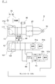
- FIG. 1 is a block diagram of a power supply device according to an embodiment of the present invention.
- 2 is a graph showing output voltage characteristics with respect to a charged state in the battery of FIG. 1. It is a block diagram of the power supply device and external charging device of FIG.
- (A) And (b) is a graph which shows the characteristic of the charge condition with respect to time in the battery of FIG. 1, (c) The graph for demonstrating the transition of the operation mode in the bidirectional
- A) And (b) is a graph which shows the characteristic of the charge condition with respect to time in the battery of FIG. 1, (c) The graph for demonstrating the transition of the operation mode in the bidirectional
- the characteristics of the output voltage (V c2 ) on the next side, (c) are graphs for explaining the operating state of the bidirectional power converter with respect to (SOC 1 ) of the battery 11.
- (a) shows the SOC characteristic of the battery with respect to time
- (b) shows the SOC characteristic of the battery with respect to time
- (c) shows the transition of the battery charge control mode.
- (D) is a graph explaining the transition of the charge control mode of the battery.
- FIG. 1 is a block diagram of a power supply apparatus according to an embodiment of the present invention.
- the power supply device of this example is mounted on a vehicle, for example, but is not necessarily limited to a vehicle, and may be applied to other devices other than the vehicle.
- the power supply device 1 includes batteries 11 and 12, an inverter 20, a motor 30, a bidirectional power converter 41, loads 51a to 51d, a DC / DC converter 60, and a controller 100.
- the battery 11 has a secondary battery 111 and a relay switch 112.
- the secondary battery 111 is a secondary battery such as a lithium ion battery, and is configured by connecting a plurality of secondary batteries in series.
- the relay switch 112 is a contact switch for electrically connecting or disconnecting between the battery 11 and the inverter 20 and the bidirectional power converter 41. The relay switch 112 is kept on except during maintenance.
- the battery 11 is a high-voltage battery, and supplies power to the motor 30 and becomes a main power source when driving the motor 30.
- the battery 12 has a secondary battery 111 and a relay switch 112.
- the secondary battery 111 is a secondary battery such as a lithium ion battery, and is configured by connecting a plurality of secondary batteries in series.
- the configurations of the secondary battery 121 and the switch 122 are basically the same as the configurations of the secondary battery 111 and the switch 112.
- the battery 12 is a low-voltage battery as compared with the battery 11. Therefore, when the secondary battery 111 and the secondary battery 121 are configured by the same battery, the number of the secondary batteries 111 is larger than the number of the secondary batteries 121.
- the power of the battery 12 is mainly supplied to the loads 51a and 51b.
- FIG. 2 the output voltage characteristic with respect to the charge condition of the batteries 11 and 12 is shown.
- SOC state of charge
- Vo output voltage
- the inverter 20 is connected to both ends of the battery 11 by a pair of power supply lines.
- the inverter 20 is a conversion circuit that converts the DC power output from the battery 11 into AC power and outputs the AC power to the motor 30, and is configured by a circuit in which a plurality of switching elements such as FETs are connected. Moreover, the inverter 20 converts the DC power from the motor 30 into AC power and outputs it when the motor 30 is regenerated.
- the motor 30 is a three-phase AC power permanent magnet motor, which is driven as a travel drive source, coupled to a vehicle drive shaft (not shown), and rotates the vehicle via the drive shaft.
- the motor 30 is connected to the inverter 20.
- the motor 30 also functions as a generator during regeneration.
- the loads 51a and 51b are connected to both ends of the battery 12 by a pair of power lines.
- the loads 51a and 51b are loads different from the motor 30, and are devices such as an air conditioner.
- the bidirectional power converter 41 is a conversion circuit that converts DC power into DC power and outputs it in both directions.
- the bidirectional power conversion unit 41 is connected between the battery 11 and the battery 12, and is connected between a power line connected to both ends of the battery 11 and a power line connected to both ends of the battery 12. Yes.
- the circuit side formed by the battery 11, the inverter 20 and the motor 30 is the primary side, and the circuit side formed by the battery 12 and the loads 51a and 51b is the secondary side.
- the bidirectional power converter 41 steps down DC power input from the primary side and supplies it to the secondary side, and boosts DC power input from the secondary side and supplies it to the secondary side.
- the bidirectional power conversion unit 41 is formed by a buck-boost chopper circuit or the like, and is included in the buck-boost chopper circuit to switch on and off switching elements such as transistors, or by maintaining the on-state of the switching elements. , Convert power. That is, the operation of the bidirectional power converter 41 is a step-down operation when power is output from the primary side to the secondary side, and a step-up operation from the secondary side to the primary side.
- the DC / DC converter 60 converts the output power from the battery 12 or the output power output from the battery 11 via the bidirectional power conversion unit 41 into DC power, and outputs the DC power to the battery 13. In addition, power is supplied to the loads 51c and 51d.
- a circuit side formed by the battery 13 and the loads 51c and 51d is defined as a tertiary side.
- the DC / DC converter 60 is a circuit that steps down the DC power supplied from the secondary side and outputs it to the tertiary side.
- the relational expression shown in the above equation (1) is established between the battery 11 and the battery 12, and the both power conversion unit 41 is a converter that steps down from the primary side to the secondary side. Therefore, compared with the voltage of the battery 11, electric power is input to the secondary side input of the DC / DC converter at a lower voltage. For this reason, the DC / DC converter 60 can reduce the component breakdown voltage on the secondary side (high voltage side), thereby reducing the size of the component.
- the battery 13 is composed of a secondary battery such as a lithium ion battery, and is a low-voltage battery.
- the battery 13 is connected to the output side of the DC / DC converter 60.
- the loads 51 c and 51 d are auxiliary machines such as a display of the navigation system, and are connected to the battery 13.
- the battery 13 serves as a power source for driving main auxiliary machines.
- the controller 100 is a control unit that controls the inverter 20, the bidirectional power conversion unit 41, and the DC / DC converter 60.
- the controller 100 generates a drive signal for switching the switching of the switching element included in the inverter 20 based on the input voltage input from the battery 11 to the inverter 20, the phase current of the motor 30, and the torque command input from the outside.
- the inverter 20 is controlled by outputting to the inverter 20.
- the controller 100 controls the bidirectional power conversion unit 41 based on the state of charge (SOC: State of Charge) of the batteries 11 and 12 and the operation state of the motor.
- SOC State of Charge
- the controller 100 controls the bidirectional power converter 41 not only during driving of the vehicle but also when the battery 11 is charged by an external power source.
- controller 100 controls the DC / DC converter 60 according to the state of charge of the battery 13 to supply power from the secondary side to the tertiary side to charge the battery 13.
- FIG. 3 is a block diagram of the power supply device and the external charging device of this example.
- the external charging device 70 includes an external power source 71 and a charger 72.
- the external charging device 70 is placed in a home parking lot or a public facility where the vehicle is parked.
- the external power supply 71 is an AC power supply.
- the charger 72 is a device that converts the AC power of the external power source 71 into DC power, supplies the DC power to the battery 11 on the vehicle side, and charges the battery 11.
- the external charging device 70 controls the charger 72 based on the state of charge of the battery 11.
- a connection terminal for connecting to a charging port 80 provided in the vehicle is provided at the tip of the wiring connected to the charger 72.
- the external charging device 70 is also provided with a controller for controlling the charger 72.
- the charging port 80 is a charging port provided on the vehicle side, and is a connection part for electrically connecting the external charging device 70 and the power supply device 1.
- the charging port 80 is electrically connected to a power supply line that connects between the inverter 20 and the battery 11, and is connected to the DC side of the inverter 20.
- the charging power of the external charging device 70 is input from the charging port 80 and supplied to the battery 11 from the DC side of the inverter 20 without passing through the bidirectional power conversion unit 41.
- Controller 100 stops the operation of bidirectional power converter 41 in order to supply power from external charging device 70 to battery 11. Specifically, the controller 100 turns off the switching element of the buck-boost chopper circuit provided in the bidirectional power converter 41. Thereby, in the power supply device 1, the electrical continuity between the primary side and the secondary side is interrupted.
- a voltage sensor (not shown) that detects a voltage between terminals of the battery 11 is connected to the power supply device 1 between the battery 11 and the inverter 20.
- the state of charge (SOC) is managed.
- the controller 100 sends a signal to the external charging device 70 indicating that the power supply device 1 side is also in a charging preparation state in a state where the operation of the bidirectional power conversion unit 41 is stopped. Send to.
- the controller 100 also transmits information on the current capacity of the battery 11 to the external charging device 70 in the signal.
- the external charging device 70 receives a signal from the controller 100, sets charging power and charging time for charging the battery 11, and is based on an operation for starting charging by the user of the external charging device 70. Start charging. When the charging state of the battery 11 reaches the full charging capacity or the target charging state set at the start of charging, the external charging device 70 ends the charging control and the connection terminal is disconnected from the charging port 80. That is, the power supply device 1 of this example charges the battery 11 in a state where the operation of the bidirectional power conversion unit 41 is stopped.
- the controller 100 stops the operation of the bidirectional power converter while the battery 11 is being charged by the external charging device 70. Therefore, even if auxiliary equipment such as the loads 51c and 51d is operated with the power of the battery 13 while the battery 11 is being charged, the high-frequency noise of the auxiliary equipment is blocked by the bidirectional power conversion unit 41. . Furthermore, since the operation of the bidirectional power conversion unit 41 is stopped, the generation of noise from the bidirectional power conversion unit 41 can also be suppressed.
- a discharge limit threshold value (SOC a ) indicating a discharge limit is set in the battery 12 in advance.
- SOC a the SOC at which the output voltage rapidly decreases with respect to the change in SOC is set to the discharge limit threshold (SOC a ).
- the controller 100 manages the SOC 2 of the battery 12 so that the state of charge (SOC 2 ) of the battery 12 does not become lower than the threshold value (SOC a ).
- the operation threshold value (SOC b ) for operating the bidirectional power conversion unit 41 is set by the state of charge (SOC 2 ) of the battery 12.
- the operation threshold (SOC b ) is set to a value higher than the discharge limit threshold (SOC a ).
- the controller 100 stops the operation of the bidirectional power converter 41 and the SOC 2 of the battery 12 is less than the operation threshold (SOC b ). In some cases, the controller 100 operates the bidirectional power conversion unit 41.
- the controller 100 operates the bidirectional power conversion unit 41
- the bidirectional power converter 41 is selected. To control.
- a current sensor for detecting the output current and a voltage sensor for detecting the output voltage are connected to the output on the secondary side of the both-side power conversion unit 41, respectively.
- a current sensor for detecting the output current and a voltage sensor for detecting the output voltage are connected to the output on the secondary side of the both-side power conversion unit 41, respectively.
- what is necessary is just to provide any one sensor, when an output voltage and an output current can be detected by any one of a current sensor and a voltage sensor.
- the controller 100 sets the power to be supplied from the battery 11 to the secondary side via the bidirectional power converter 41 in accordance with the required power of the loads 51a to 51d. Then, the controller 100 switches the switching element provided in the bidirectional power converter 41 so that the secondary output current of the bidirectional power converter 41 becomes a current for outputting the supplied power. .
- the current control of the bidirectional power converter 41 is performed based on the output current on the secondary side of the bidirectional power converter 41.
- the controller 100 switches the switching element of the bidirectional power converter 41 so that the output voltage of the battery 12 and the output voltage of the secondary side of the bidirectional power converter 41 are the same voltage. Make it work.
- the output voltage of the battery 12 and the output voltage on the secondary side of the bidirectional converter 41 are the same voltage, the discharge from the battery 12 is suppressed, and the output of the battery 11 via the bidirectional power converter 41 is suppressed. Electric power is supplied to the loads 51a to 51d.
- the voltage control of the bidirectional power converter 41 is performed based on the output voltage on the secondary side of the bidirectional power converter 41.
- the controller 100 stops the operation of the bidirectional power conversion unit 41 (non-operation mode). Further, the controller 100 operates the bidirectional power conversion unit 41 with current control when the state of charge (SOC 2 ) of the battery 12 is equal to or lower than the operation threshold (SOC b ) and higher than the discharge limit threshold (SOC a ). Let The controller 100, when the state of charge of the battery 12 (SOC 2) is equal to or less than the discharge limit threshold (SOC a) operates the bidirectional power conversion unit 41 with the voltage control.
- FIG. 4A illustrates the SOC characteristic of the battery 11 with respect to time
- FIG. 4B illustrates the SOC characteristic of the battery 12 with respect to time
- FIG. 4C illustrates the transition of the operation mode of the bidirectional power converter 41. It is a graph for.
- the state of charge of battery 11 is SOC 1 and the state of charge of battery 12 is SOC 2 .
- SOC 1 of battery 11 is in a sufficiently high state for driving motor 30, and SOC 2 of battery 12 is in a sufficiently high state for operating loads 51 a to 51.
- the state of charge (SOC 1 ) of the battery 11 is time. It goes down as time passes. Further, when the loads 51a to 51d are operated with the electric power of the battery 12, as shown in FIG. 4B, the state of charge (SOC 2 ) of the battery 12 decreases with time. At this time, since the state of charge (SOC 2 ) of the battery 12 is higher than the operation threshold value (SOC b ), the operation of the bidirectional power converter 41 is stopped (non-operation mode).
- the state of charge (SOC 2 ) of the battery 12 reaches the discharge limit threshold (SOC a ), so that the controller 100 changes from the current control mode to the voltage control mode.
- the bidirectional power converter 41 is operated.
- the state of charge (SOC) from time (t 2 ) to time (t 3 ) is determined from the slope of the state of charge (SOC 2 ) from time (t 1 ) to time (t 2 ).
- the slope of 2 ) is smaller, and the slope of the state of charge (SOC 2 ) from time (t 2 ) to time (t 3 ) is zero.
- a regenerative limit threshold value (SOC c ) that limits charging by regeneration of the motor 30 is set in the battery 11 in advance.
- SOC 1 state of charge
- SOC c regeneration limit threshold value
- the controller 100 operates the bidirectional power converter 41 to generate 2 electric power generated by regeneration of the motor 30.
- the battery 12 is charged by supplying to the next side.
- the controller 100 sets the bidirectional power so that the input voltage on the primary side of the bidirectional power converter 41 becomes the same voltage as the output voltage of the battery 11 corresponding to the state of charge (SOC 1 ) of the battery 11.
- the switching element of the converter 41 is switched. That is, the controller 100 controls the bidirectional power conversion unit 41 by voltage control to charge the battery 12. Thereby, the voltage of the battery 11 rises during charging of the battery 12 by regeneration, thereby preventing overcharging.
- the controller 100 does not operate the bidirectional power conversion unit 4 and does not supply power to the secondary side.
- FIG. 5A illustrates the SOC characteristic of the battery 11 with respect to time
- FIG. 5B illustrates the SOC characteristic of the battery 12 with respect to time
- FIG. 5C illustrates the transition of the operation mode of the bidirectional power converter 41. It is a graph for. As an initial condition, it is assumed that the state of charge (SOC 1 ) of the battery 11 is higher than the regeneration limit threshold (SOC c ), and the SOC 2 of the battery 12 is higher than the operation threshold (SOC b ).
- the motor 30 performs a power running operation from time (0) to time (t 1 ), from time (t 2 ) to time (t 3 ), and from time (t 1 ) to time (t 2 ). It is assumed that the regenerative operation is performed between time (t 3 ) and time (t 4 ).
- the controller 100 When the motor 30 is switched from the power running operation to the regenerative operation at the time (t 1 ), the state of charge (SOC 1 ) of the battery 11 is higher than the regenerative limit threshold value (SOC c ) at this time, so the controller 100 The power conversion unit 41 is voltage-controlled, and the electric power generated by the regenerative operation of the motor 30 is supplied to the battery 12.
- the controller 100 stops the operation of the bidirectional power conversion unit 41. Then, when the motor 30 is switched from the power running operation to the regenerative operation at time (t 3 ), the state of charge (SOC 1 ) of the battery 11 is lower than the regenerative limit threshold value (SOC c ) at this time. The operation of the bidirectional power converter 41 is stopped, and the power generated by the regenerative operation of the motor 30 is supplied to the battery 11. As a result, the batteries 11 and 12 are charged while preventing overcharging of the batteries 11 and 12 during the regenerative operation of the motor 30.
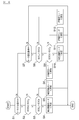
- FIG. 6 is a flowchart showing a control procedure of the power supply device of this example. Note that the steps shown in FIG. 6 are repeatedly performed at a predetermined cycle.
- step S1 the controller 100 confirms the operation state of the motor 30 and determines whether or not the motor 30 is performing a power running operation.
- the operating state of the motor 30 may be specified by an access opening degree, a vehicle speed, or the like.
- step S2 the controller 100 compares the state of charge (SOC 2 ) of the battery 12 with the operation threshold (SOC b ).
- the controller 100 compares the state of charge (SOC 2 ) of the battery 12 with the discharge limit threshold (SOC a ) in step S3. . If the state of charge (SOC 2 ) is higher than the discharge limit threshold (SOC a ), in step S4, the controller 100 sets the current control mode to output current on the secondary side of the bidirectional power converter 41.
- the bidirectional power converter 41 is controlled based on the above. Thereby, the electric power of the battery 11 and the battery 12 is supplied to load 51a, 51b.
- step S5 when the state of charge (SOC 2 ) is equal to or lower than the discharge limit threshold (SOC a ), in step S5, the controller 100 sets the voltage control mode, and the bidirectional power converter 41 The bidirectional power converter 41 is controlled based on the output voltage on the secondary side. Thereby, the electric power of the battery 11 is supplied to load 51a, 51b.
- step S6 if the state of charge (SOC 2 ) is higher than the operation threshold value (SOC b ), in step S6, the controller 100 sets the non-operation mode and operates the bidirectional power conversion unit 41. Stop. Thereby, the electric power of the battery 12 is supplied to the loads 51a and 51b.
- step S7 if the motor 30 is not performing a power running operation, it is determined in step S7 whether the motor 30 is performing a regenerative operation. If the motor 30 is performing a regenerative operation, the controller 100 compares the state of charge (SOC 1 ) of the battery 11 with the regenerative limit threshold (SOC c ) in step S8.
- SOC 1 state of charge
- SOC c regenerative limit threshold
- the controller 100 compares the state of charge (SOC 2 ) of the battery 12 with the regeneration limit threshold (SOC d ) in step S9. .
- the regeneration limit threshold value (SOC d ) is a threshold value set for the battery 12, similar to the regeneration limit threshold value (SOC c ) of the battery 11.
- the controller 100 sets the voltage control mode in step S10 and the primary side of the bidirectional power converter 41.
- the bidirectional power converter 41 is controlled based on the output voltage. Thereby, the battery 12 is charged.
- step S9 if the state of charge (SOC 2 ) is greater than or equal to the regeneration limit threshold value (SOC d ), the controller 100 sets the non-operation mode to stop the operation of the bidirectional power converter 41, Neither the batteries 11 and 12 are charged.
- step S8 if the state of charge (SOC 1 ) is equal to or less than the regeneration limit threshold (SOC c ), the controller 100 sets the non-operation mode to stop the operation of the bidirectional power converter 41, The battery 11 is charged.
- step S12 if the motor 30 is not performing a regenerative operation, in step S12, the controller 100 sets the non-operation mode and stops the operation of the bidirectional power converter 41.
- the controller 100 performs bidirectional power conversion.
- the operation of the unit 41 is stopped. Thereby, since the electric power from the external charging device 70 is supplied to the battery 11 without going through the bidirectional power converter 41, the loss of the bidirectional power converter 41 can be suppressed and the charging time can be shortened. . Further, high-frequency noise generated by auxiliary devices and converters connected to the secondary side of the bidirectional power conversion unit 41 is prevented from leaking to the primary side circuit including the battery 11 and the external charging device 70. Can do. In addition, when the battery 11 is charged using the external charging device 70, the operation of the bidirectional power conversion unit 41 is stopped, so that the generation of noise in the bidirectional power conversion unit 41 is suppressed. Can do.
- the charging power of the external power supply device 70 is supplied from the DC side of the inverter 20 to the battery 11 without going through the bidirectional power converter 41.
- the loss of the bidirectional power converter 41 can be suppressed and the charging time can be shortened.
- the operation of the bidirectional power conversion unit 41 can be stopped, so that the generation of noise in the bidirectional power conversion unit 41 can be suppressed. it can.
- the full charge voltage of the battery 11 is higher than the full charge voltage of the battery 12.
- the component breakdown voltage on the secondary side (high voltage side) of the DC / DC converter 60 can be lowered, and the size of the component can be reduced.
- the controller 100 stops the operation of the bidirectional power conversion unit 41.
- the controller 100 stops the operation of the bidirectional power conversion unit 41.
- the auxiliary machines 51a and 51b can be operated with the power of the battery 12 without using the power of the battery 11, the power consumption of the battery 11 can be suppressed, and as a result, the travel distance can be extended.
- the bidirectional power conversion unit 41 is operated to convert the power of the battery 11 into the bidirectional power conversion unit 41. To the loads 51a and 51b.
- the state of charge (SOC 2 ) becomes lower than the operation threshold value (SOC b )
- the bidirectional power conversion unit 41 loads the loads 51 a and 51 b. To control the output current to be supplied to the loads 51a and 51b.
- SOC 2 state of charge
- SOC b operation threshold value
- SOC b operation threshold value
- the bidirectional power conversion unit 41 supplies the loads 51 a and 51 b based on the output voltage of the battery 12.
- the power of the battery 11 is supplied to the loads 51a and 51b, and the discharge of the battery 12 is suppressed. Thereby, it is possible to prevent the output voltage of the battery 12 from rapidly decreasing near the discharge limit threshold (SOC a ).
- the electric power generated by the regeneration of the motor 30 is supplied to the battery 12 via the inverter 20 and the bidirectional power converter 41 to charge the battery 12.
- the energy generated by the regeneration of the motor 30 can be used efficiently, and overcharging of the battery 11 can be prevented.
- the electric power generated by the regeneration is supplied to the battery 12.
- the charging state (SOC 2 ) of 12 is higher than the regeneration limit threshold (SOC d )
- the power generated by regeneration may be supplied to the loads 51a to 51d.
- the bidirectional power conversion unit 41 is a converter that converts the power from the primary side and the power from the secondary side, respectively, and outputs the converted power, but at least the primary side. It may be a converter that converts DC power from the output and outputs DC power to the secondary side.
- the battery 11 corresponds to the “first battery” of the present invention
- the battery 12 corresponds to the “second battery” of the present invention
- the bidirectional power conversion unit 41 corresponds to the “first power converter”
- the controller 100 corresponds to a “control unit”.
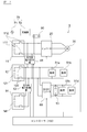
- FIG. 7 is a block diagram of a power supply device and an external charging device according to another embodiment of the invention.
- two-way power converter 42 differs from 1st Embodiment mentioned above.
- Other configurations are the same as those in the first embodiment described above, and the description thereof is incorporated.
- the power supply device 1 further includes a battery 14 and a bidirectional power converter 42.
- the battery 14 includes a secondary battery 141 and a relay switch 142.
- the secondary battery 141 is a secondary battery such as a lithium ion battery, and is configured by connecting a plurality of secondary batteries in series.
- the relay switch 142 is a switch for electrically connecting or disconnecting the battery 14 and the bidirectional power converter 42.
- the relay switch 142 is kept on except during maintenance.
- the battery 14 is a low-voltage battery lower than the battery 11, and is a battery mainly for operating the loads 51a to 51d.
- the bidirectional power converter 42 is a conversion circuit that converts DC power into DC power and outputs it in both directions.
- the bidirectional power conversion unit 42 is connected between the battery 14 and the battery 12, and is connected between a power supply line connected to both ends of the battery 14 and a power supply line connected to both ends of the battery 12. Yes.
- the circuit side formed by the battery 14 and the bidirectional power conversion unit 42 is a tertiary side.
- the bidirectional power converter 42 converts DC power input from the tertiary side and supplies it to the secondary side, and converts DC power input from the secondary side and supplies it to the tertiary side.
- the bidirectional power converter 42 is formed by a buck-boost chopper circuit or the like. Thereby, the electric power of the battery 14 is converted by the bidirectional power converter 42 and supplied to the loads 51 a and 51 b and the DC / DC converter 60.
- the controller 100 controls the bidirectional power converter 42 based on the voltage of the battery 12 and the voltage of the battery 14.
- the bidirectional power conversion unit 4 is operated to supply the power of the battery 41 to the circuit on the secondary side.
- the bidirectional power conversion unit 42 is operated according to the state of charge (SOC 4 ) of the battery 14, and the power of the battery 14 is transferred to the secondary circuit. Supply. That is, when the state of charge (SOC 2 ) of the battery 12 becomes equal to or lower than the operation threshold value (SOC b ), the power of the battery 14 is preferentially supplied to the secondary circuit over the power of the battery 11.
- the controller 100 detects that the remaining capacity of the battery 12 is reduced and detects from the detection voltage of the sensor of the battery 12 that the state of charge (SOC 2 ) of the battery 12 is equal to or lower than the operation threshold (SOC b ), the current state Thus, if the power supply from the battery 12 is continued, it is determined that the battery 12 may be over-discharged. Then, the controller 100 compares the charge capacity of the battery 14 with the discharge limit threshold (SOC d ) of the battery 14.
- the discharge limit threshold value is a threshold value that is set in advance and that indicates the limit of discharge for protecting the battery 14.
- the controller 100 controls the current of the bidirectional power converter 42 and supplies the power of the battery 14 to the secondary circuit.
- the controller 100 controls the bidirectional power conversion unit 41 so that the bidirectional power conversion unit 41 is stopped and the power of the battery 11 is not supplied to the secondary circuit.
- the bidirectional power converter 41 is not operating, high frequency noise generated in the DC / DC converter 60, the loads 51a to 51d and the bidirectional power converter 42 is prevented from leaking to the primary circuit. be able to.
- the controller 100 When charging the battery 11 with the external charging device 70, the controller 100 stops the bidirectional power converter 41 and the bidirectional power converter 42 and charges the battery 11. Thereby, the generation of noise from the bidirectional power converter 41 and the bidirectional power converter 42 can be suppressed during charging of the battery 11 by the external power source 71.
- the bidirectional power converter 42 that converts the DC power of the battery 14 between the battery 12 and the battery 14 and supplies the DC power to the loads 51 a to 51 d and the DC / DC converter 60. It has. Thereby, since the electric power from the external charging device 70 is supplied to the battery 11 without going through the bidirectional power converters 41 and 42, the loss of the bidirectional power converter 41 is suppressed and the charging time is shortened. Can do. In addition, the generation of noise from the bidirectional power converters 41 and 42 can be suppressed.
- the bidirectional power converter 42 is operated to change the power of the battery 14 to the bidirectional power converter 42.
- two-way power converter 41 since the bidirectional
- FIG. 8 is a block diagram of a power supply device and an external charging device according to another embodiment of the invention. This example is different from the first embodiment described above in that the battery 12 can be detached from the power supply device 1. Other configurations are the same as those of the first embodiment described above, and the descriptions of the first and second embodiments are incorporated as appropriate.
- the battery 12 provided in the power supply device 1 of this example is a battery that can be detached from the power supply device 1 and is a battery that can be connected to the external charging device 90 and charged by the external power supply 91.
- the external charging device 90 is a charging device that is smaller than the external charging device 70 and can be set in a house.
- the external power supply 91 is a household 100V or 200V AC power supply.
- the configuration of the charger 92 is the same as that of the charger 72.
- the battery 15 is the same battery as the battery 12, and is a spare (auxiliary) battery for the battery 12.
- the battery 12 can be brought into the house and the battery 12 can be charged from the external power source 91 which is a household power source using the external charging device 90. Further, by mounting the spare battery 15 in the power supply device while the battery 12 is being charged, the vehicle can be driven while the battery 12 is being charged.
- the present invention can shorten the entire charging time by replacing the auxiliary battery 15 and the battery 12.
- FIG. 9 is a block diagram of a power supply apparatus according to another embodiment of the invention. This example is different from the above-described first embodiment in that the battery 12 is not connected. Other configurations are the same as those of the first embodiment described above, and the descriptions of the first to third embodiments are incorporated as appropriate.
- the battery 12 is not connected to the power supply device 1 of this example. Therefore, the battery 11 supplies power not only to the motor 30 but also to the loads 51a to 51d while the vehicle including the power supply device 1 is traveling.
- the control unit 10 controls the bidirectional power conversion unit 41 based on the state of charge (SOC 1 ) or the output voltage (V 1 ) of the battery 11 to supply the power of the battery 11 to the DC / DC converter 60.
- SOC 1 state of charge
- V 1 output voltage
- an operating voltage range (V cd ) is set in advance with respect to the input voltage to the DC / DC converter 60 (input voltage input from the secondary circuit).
- the input voltage In order to operate the DC / DC converter 60, the input voltage must be within the operating voltage range.
- the battery 11 is a high voltage battery, and when the state of charge (SOC 1 ) of the battery 11 is high, the output voltage of the battery 11 is higher than the upper limit voltage of the operating range.
- the controller 100 compares the output voltage of the battery 11 with the operating range of the DC / DC converter 60. When the output voltage is higher than the upper limit voltage of the operating range, the controller 100 turns on the switching element of the bidirectional power converter 41. By switching off, the input voltage from the primary side is stepped down to keep the output voltage to the secondary side within the operating voltage range. The output voltage to the secondary side of the bidirectional power converter 41 is input to the DC / DC converter 60 without large voltage fluctuation. Accordingly, the controller 100 switches the switching element of the bidirectional power conversion unit 41 according to the output voltage of the battery 11 to step down the output voltage of the battery 11 within the voltage operation range of the DC / DC converter 60. .
- the controller 100 keeps the switching element of the bidirectional power converter 41 in the ON state, The voltage drop of the input voltage from the secondary side is reduced and output to the secondary side.
- the switching element of the bidirectional power conversion unit 41 does not perform the switching operation and is maintained in the ON state, the voltage drop between the input and output of the bidirectional power conversion unit 41 is a voltage drop due to the ON resistance of the switching element. It becomes. That is, the voltage drop when the switching element of the bidirectional power conversion unit 41 is kept on is smaller than the voltage drop when the switching element is switched. Therefore, in this example, when the output voltage of the battery 11 is within the operating range, the controller 100 keeps the switching element of the bidirectional power conversion unit 41 in the on state and supplies the power of the battery 1 to DC / DC. Input to the converter 60.
- the output voltage (V 1 ) of the battery 11 is higher than the upper limit voltage (V h1 ).
- the controller 100 performs a switching operation of the switching element of the bidirectional power converter 41 in order to step down the output voltage (V 1 ) to the upper limit voltage (V h1 ).
- the output voltage (V c2 ) on the secondary side of the bidirectional power converter 41 is equal to or lower than the upper limit voltage (V h1 ), and the DC / DC converter 60 is within the operating range. It can be operated.
- the output voltage (V 1 ) of the battery 11 is equal to or lower than the upper limit voltage (V h1 ) and is within the operating voltage range (V cd ). . Since the controller 100 does not need to greatly reduce the output voltage (V 1 ), the controller 100 maintains the switching element of the bidirectional power converter 41 in the ON state. As a result, as shown in FIG. 10B, the output voltage (V c2 ) on the secondary side of the bidirectional power converter 41 can be kept within the operating voltage range of the DC / DC converter 60.
- the controller 100 turns on the switching element of the bidirectional power conversion unit 41 so that the voltage of the battery 11 falls within the operating voltage range of the DC / DC converter 60. 60.
- the controller 100 turns on the switching element of the bidirectional power conversion unit 41 so that the voltage of the battery 11 falls within the operating voltage range of the DC / DC converter 60. 60.
- power can be supplied to the DC / DC converter 60 while the switching element of the bidirectional power converter 41 is kept on. Power loss can be suppressed.
- the travel distance of the vehicle equipped with the power supply device 1 of this example can be extended.
- the switching element of the bidirectional power converter 41 when the output voltage (V 1 ) of the battery 11 is equal to or lower than the upper limit voltage (V h1 ), the switching element of the bidirectional power converter 41 is turned on.
- the threshold voltage of the output voltage (V 1 ) of the battery 11 that turns on the switching element may be set to a voltage higher than the upper limit voltage (V h1 ) in consideration of the voltage drop due to.
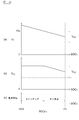
- FIG. 11 is a graph for explaining voltage characteristics and charge control modes of the batteries 11 and 12 in a power supply device according to another embodiment of the invention.
- the charging control of the battery 12 is different from the first embodiment described above.
- Other configurations are the same as those of the first embodiment described above, and the descriptions of the first to fourth embodiments are incorporated as appropriate.
- the power supply device 1 according to this example will be described with reference to FIGS.
- the charging port 80 is connected to the external charging device 70, the battery 11 and the battery 12 are charged.
- the configurations of the power supply device 1 and the external charging device 70 of this example are the same as the configurations shown in FIG. Hereinafter, the charging control by the controller 100 will be described.
- the controller 100 gives priority to the charging of the battery 11 over the battery 12 when performing the charging control by the external charging device 70. Therefore, first, the controller 100 stops the bidirectional power conversion unit 41 and supplies power from the external charging device 70 to the battery 11.
- a fully charged state (SOC max1 ) is set as a charged state indicating full charge according to the nature and capacity of the secondary battery 121.
- the battery 12 is also set to a fully charged state (SOC max2 ).
- a threshold charge state (SOC ch ) for switching from charging of the battery 11 to charging of the battery 12 is set.
- the threshold charge state (SOC ch ) is set to a lower SOC than the full charge state (SOC max1 ).
- the controller 100 charges the battery 11 with the bidirectional power conversion unit 41 stopped.
- controller 100 when the charging state of battery 11 becomes higher than the threshold charging state (SOC ch ), controller 100 once stops charging from external power supply device 70. In order to stop charging from the external charging device 70, the controller 100 transmits a signal to stop charging to the controller 100 of the external charging device 70. Alternatively, when the controller 100 has a function of controlling the charger 72, a charge stop control signal is transmitted to the charger 72. In this state, the external charging device 70 and the power supply device 1 remain electrically connected, and the connection terminal of the external charging device 70 is connected to the charging port 80.
- SOC ch threshold charging state
- the controller 100 switches the switching element of the bidirectional power conversion unit 41 so that the power charged in the battery 11 passes through the bidirectional power conversion unit 41 to the battery. 12 to charge the battery 12.
- the controller 100 manages the state of charge of the battery 12 from the voltage of the battery 12. When the charged state of the battery 12 is lower than the fully charged state (SOC max2 ), the operation of the bidirectional power conversion unit 41 is continued. When the charged state of the battery 12 reaches the fully charged state (SOC max2 ), the controller 100 stops the operation of the bidirectional power conversion unit 41.
- controller 100 starts charging control of battery 11 again by external charging device 70 and charges until the charging capacity of battery 11 reaches the full charge capacity (SOC max1 ).
- FIG. 11 (a) shows the SOC characteristics of the battery 11 with respect to time
- FIG. 11 (b) shows the SOC characteristics of the battery 12 with respect to time
- FIG. 11 (c) illustrates the transition of the charge control mode of the battery 11
- FIG. 11D is a graph for explaining the transition of the charge control mode of the battery 12.
- the charged state of the batteries 11 and 12 is set to 0 percent as an initial condition.
- the controller 100 When the controller 100 recognizes that the external charging device 70 is connected at time (0), the controller 100 sets the charging control mode of the battery 11 to the charging mode. When the charging control mode of the battery 11 is set to the charging mode, the controller 100 stops both the power conversion units 41 and supplies the battery 11 with the power from the external charging device 70. Between time (0) and time (t 1 ), the charging state of the battery 11 gradually increases as the charging time elapses. The controller 100 manages the charge state of the battery 11 from the voltage of the battery 11 while the battery 11 is being charged.
- the controller 100 sets the charging control mode of the battery 11 to the stop mode and sets the charging control mode of the battery 12 to the charging mode. And When the charging control mode of the battery 12 is set to the charging mode, the controller 100 switches the switching element of the power converter 41 to supply the power from the battery 11 to the battery 12.
- the charging control mode of the battery 11 is a stop mode, and the controller 100 stops the power supply from the external charging device 70.
- the charging state of the battery 12 gradually increases as the charging time elapses.
- the state of charge of the battery 11 gradually decreases as power is supplied to the battery 12.
- the controller 100 manages the state of charge of the battery 12 from the voltage of the battery 12 while the battery 12 is being charged.
- the controller 100 Since the charged state of the battery 12 reaches the fully charged state (SOC max2 ) at time (t 2 ), the controller 100 sets the charging control mode of the battery 12 to the stop mode and sets the charging control mode of the battery 11 to the charging mode. . Then, between time (t 2 ) and time (t 3 ), the state of charge of the battery 11 rises again, and at time (t 3 ), the state of charge of the battery 11 reaches the fully charged state (SOC max1 ). The controller 100 ends the charging control of the batteries 11 and 12.
- the bidirectional power conversion unit 41 when the charge capacity of the battery 11 is higher than the threshold charge state (SOC ch ) and the charge capacity of the battery 12 is lower than the full charge state (SOC max2 ), the bidirectional power conversion unit 41.
- SOC ch threshold charge state
- SOC max2 full charge state
- the threshold charge state (SOC ch ) in this example corresponds to the “predetermined threshold capacity” of the present invention.
Landscapes
- Engineering & Computer Science (AREA)
- Power Engineering (AREA)
- Transportation (AREA)
- Mechanical Engineering (AREA)
- Life Sciences & Earth Sciences (AREA)
- Sustainable Development (AREA)
- Sustainable Energy (AREA)
- Charge And Discharge Circuits For Batteries Or The Like (AREA)
- Control Of Charge By Means Of Generators (AREA)
- Dc-Dc Converters (AREA)
- Electric Propulsion And Braking For Vehicles (AREA)
Abstract
La présente invention concerne un appareil d'alimentation en énergie qui comprend : une première batterie qui fournit de l'énergie à au moins un moteur (30) ; une seconde batterie qui fournit de l'énergie à une première charge distincte du moteur (30) ; un premier convertisseur de puissance qui est connecté entre la première batterie et la seconde batterie et qui délivre un courant continu vers la première charge ou la seconde batterie par la conversion du courant continu d'au moins la première batterie ; et une unité de commande qui arrête le fonctionnement du convertisseur de puissance lorsque la charge de la première batterie est réalisée à l'aide d'une alimentation externe.
Applications Claiming Priority (2)
| Application Number | Priority Date | Filing Date | Title |
|---|---|---|---|
| JP2012-039943 | 2012-02-27 | ||
| JP2012039943A JP2013176251A (ja) | 2012-02-27 | 2012-02-27 | 電源装置 |
Publications (1)
| Publication Number | Publication Date |
|---|---|
| WO2013129231A1 true WO2013129231A1 (fr) | 2013-09-06 |
Family
ID=49082431
Family Applications (1)
| Application Number | Title | Priority Date | Filing Date |
|---|---|---|---|
| PCT/JP2013/054332 Ceased WO2013129231A1 (fr) | 2012-02-27 | 2013-02-21 | Appareil d'alimentation en énergie |
Country Status (2)
| Country | Link |
|---|---|
| JP (1) | JP2013176251A (fr) |
| WO (1) | WO2013129231A1 (fr) |
Cited By (4)
| Publication number | Priority date | Publication date | Assignee | Title |
|---|---|---|---|---|
| WO2016095936A1 (fr) * | 2014-12-15 | 2016-06-23 | Volvo Truck Corporation | Procédé et dispositif pour charger un système de stockage d'énergie électrique dans un véhicule |
| CN110182150A (zh) * | 2018-02-22 | 2019-08-30 | 本田技研工业株式会社 | 车辆用电源装置 |
| CN111527689A (zh) * | 2017-12-27 | 2020-08-11 | 日本电产株式会社 | 马达控制装置 |
| CN111823951A (zh) * | 2020-06-29 | 2020-10-27 | 永安行科技股份有限公司 | 助力车动力电池系统及持续供能控制方法 |
Families Citing this family (8)
| Publication number | Priority date | Publication date | Assignee | Title |
|---|---|---|---|---|
| JP6227984B2 (ja) * | 2013-11-27 | 2017-11-08 | 京セラ株式会社 | 電力変換装置及び電力変換方法 |
| JP6502088B2 (ja) * | 2014-12-25 | 2019-04-17 | 国立大学法人横浜国立大学 | 電源システム、車両及び電圧制御方法 |
| JP6596965B2 (ja) * | 2015-06-23 | 2019-10-30 | 三菱自動車工業株式会社 | 電動車両 |
| JP2017212775A (ja) * | 2016-05-23 | 2017-11-30 | 三菱自動車工業株式会社 | 電動車両 |
| JP2018098827A (ja) * | 2016-12-08 | 2018-06-21 | 富士通株式会社 | 電源装置、電源装置の制御回路及び電源装置の制御方法 |
| JP7024667B2 (ja) * | 2018-08-30 | 2022-02-24 | トヨタ自動車株式会社 | 車両用電源システム |
| JP7196702B2 (ja) * | 2019-03-14 | 2022-12-27 | 株式会社デンソー | 高電圧補機および高電圧補機制御システム |
| JP2023183198A (ja) * | 2022-06-15 | 2023-12-27 | 三菱重工業株式会社 | 移動体、移動体の電力制御方法及びプログラム |
Citations (4)
| Publication number | Priority date | Publication date | Assignee | Title |
|---|---|---|---|---|
| JP2003333835A (ja) * | 2002-05-10 | 2003-11-21 | Toyota Motor Corp | 電源システム、電源制御方法、および電源制御をコンピュータに実行させるプログラムを記録したコンピュータ読取り可能な記録媒体 |
| JP2009131077A (ja) * | 2007-11-26 | 2009-06-11 | Toyota Motor Corp | 車両の電源装置 |
| JP2010183672A (ja) * | 2009-02-03 | 2010-08-19 | Toyota Motor Corp | 充電システム、電動車両および充電制御方法 |
| JP2010200529A (ja) * | 2009-02-26 | 2010-09-09 | Omron Corp | 充電制御装置および方法、充電装置、並びに、プログラム |
-
2012
- 2012-02-27 JP JP2012039943A patent/JP2013176251A/ja active Pending
-
2013
- 2013-02-21 WO PCT/JP2013/054332 patent/WO2013129231A1/fr not_active Ceased
Patent Citations (4)
| Publication number | Priority date | Publication date | Assignee | Title |
|---|---|---|---|---|
| JP2003333835A (ja) * | 2002-05-10 | 2003-11-21 | Toyota Motor Corp | 電源システム、電源制御方法、および電源制御をコンピュータに実行させるプログラムを記録したコンピュータ読取り可能な記録媒体 |
| JP2009131077A (ja) * | 2007-11-26 | 2009-06-11 | Toyota Motor Corp | 車両の電源装置 |
| JP2010183672A (ja) * | 2009-02-03 | 2010-08-19 | Toyota Motor Corp | 充電システム、電動車両および充電制御方法 |
| JP2010200529A (ja) * | 2009-02-26 | 2010-09-09 | Omron Corp | 充電制御装置および方法、充電装置、並びに、プログラム |
Cited By (7)
| Publication number | Priority date | Publication date | Assignee | Title |
|---|---|---|---|---|
| WO2016095936A1 (fr) * | 2014-12-15 | 2016-06-23 | Volvo Truck Corporation | Procédé et dispositif pour charger un système de stockage d'énergie électrique dans un véhicule |
| CN107107764A (zh) * | 2014-12-15 | 2017-08-29 | 沃尔沃卡车集团 | 用于对车辆中的电能存储系统充电的方法和装置 |
| US10377261B2 (en) | 2014-12-15 | 2019-08-13 | Volvo Truck Corporation | Method and device for charging an electric energy storage system in a vehicle |
| CN107107764B (zh) * | 2014-12-15 | 2020-08-14 | 沃尔沃卡车集团 | 用于对车辆中的电能存储系统充电的方法和装置 |
| CN111527689A (zh) * | 2017-12-27 | 2020-08-11 | 日本电产株式会社 | 马达控制装置 |
| CN110182150A (zh) * | 2018-02-22 | 2019-08-30 | 本田技研工业株式会社 | 车辆用电源装置 |
| CN111823951A (zh) * | 2020-06-29 | 2020-10-27 | 永安行科技股份有限公司 | 助力车动力电池系统及持续供能控制方法 |
Also Published As
| Publication number | Publication date |
|---|---|
| JP2013176251A (ja) | 2013-09-05 |
Similar Documents
| Publication | Publication Date | Title |
|---|---|---|
| WO2013129231A1 (fr) | Appareil d'alimentation en énergie | |
| CN103119822B (zh) | 蓄电系统以及蓄电系统的控制方法 | |
| US9315112B2 (en) | Power source apparatus for electrically powered vehicle and control method therefor | |
| CN103492214B (zh) | 电动车辆的电源装置及其控制方法 | |
| KR101189237B1 (ko) | 하이브리드 자동차의 충전장치 및 방법 | |
| US8963482B2 (en) | Power supply apparatus for electrically powered vehicle and method for controlling the same | |
| KR101171908B1 (ko) | 플러그인 하이브리드 자동차의 충전장치 | |
| US9960612B2 (en) | Charging and discharging system for a vehicle including a first fuse in the vehicle and a second fuse in a cable connected to the vehicle | |
| KR102478091B1 (ko) | 차량용 배터리 충전 제어 시스템 및 방법 | |
| US10625622B2 (en) | Power supply device of vehicle | |
| JP5759060B2 (ja) | 電源装置及びその制御方法 | |
| CN113711457A (zh) | 转换装置、转换系统、切换装置、包括这些装置的车辆及控制方法 | |
| US9493081B2 (en) | Power supply system, vehicle equipped with the same, and control method for power supply system | |
| JP2013074733A (ja) | 充電制御装置 | |
| CN103182951A (zh) | 电动汽车及其集成控制系统 | |
| KR101330349B1 (ko) | 전력 변환 장치 및 이를 이용한 전력 변환 방법 | |
| JP6204797B2 (ja) | 車両用電源装置 | |
| JPWO2014061137A1 (ja) | 電源管理システムおよび電源管理方法 | |
| WO2015071712A1 (fr) | Système de charge et de décharge ayant un verrou de connecteur | |
| JP2015122866A (ja) | 電動車両の充放電システム | |
| JP2013027236A (ja) | バッテリの充電システムおよび車両の充電システム | |
| KR20150121639A (ko) | 하이브리드 자동차의 구동회로 및 그 제어방법 | |
| US20160288649A1 (en) | Vehicle and charging and discharging system using vehicle | |
| JP2013070547A (ja) | 電力変換装置 | |
| WO2015068596A1 (fr) | Dispositif de charge, véhicule, système de charge de véhicule, procédé de charge et programme |
Legal Events
| Date | Code | Title | Description |
|---|---|---|---|
| 121 | Ep: the epo has been informed by wipo that ep was designated in this application |
Ref document number: 13754383 Country of ref document: EP Kind code of ref document: A1 |
|
| NENP | Non-entry into the national phase |
Ref country code: DE |
|
| 122 | Ep: pct application non-entry in european phase |
Ref document number: 13754383 Country of ref document: EP Kind code of ref document: A1 |