WO2013129377A1 - Élément de distribution d'électricité concentré, et procédé de fabrication de celui-ci - Google Patents
Élément de distribution d'électricité concentré, et procédé de fabrication de celui-ci Download PDFInfo
- Publication number
- WO2013129377A1 WO2013129377A1 PCT/JP2013/054902 JP2013054902W WO2013129377A1 WO 2013129377 A1 WO2013129377 A1 WO 2013129377A1 JP 2013054902 W JP2013054902 W JP 2013054902W WO 2013129377 A1 WO2013129377 A1 WO 2013129377A1
- Authority
- WO
- WIPO (PCT)
- Prior art keywords
- bus bar
- pair
- central axis
- arms
- tip
- Prior art date
- Legal status (The legal status is an assumption and is not a legal conclusion. Google has not performed a legal analysis and makes no representation as to the accuracy of the status listed.)
- Ceased
Links
Images



Classifications
-
- H—ELECTRICITY
- H02—GENERATION; CONVERSION OR DISTRIBUTION OF ELECTRIC POWER
- H02K—DYNAMO-ELECTRIC MACHINES
- H02K3/00—Details of windings
- H02K3/04—Windings characterised by the conductor shape, form or construction, e.g. with bar conductors
- H02K3/28—Layout of windings or of connections between windings
-
- H—ELECTRICITY
- H02—GENERATION; CONVERSION OR DISTRIBUTION OF ELECTRIC POWER
- H02K—DYNAMO-ELECTRIC MACHINES
- H02K3/00—Details of windings
- H02K3/46—Fastening of windings on the stator or rotor structure
- H02K3/52—Fastening salient pole windings or connections thereto
- H02K3/521—Fastening salient pole windings or connections thereto applicable to stators only
- H02K3/522—Fastening salient pole windings or connections thereto applicable to stators only for generally annular cores with salient poles
-
- H—ELECTRICITY
- H01—ELECTRIC ELEMENTS
- H01R—ELECTRICALLY-CONDUCTIVE CONNECTIONS; STRUCTURAL ASSOCIATIONS OF A PLURALITY OF MUTUALLY-INSULATED ELECTRICAL CONNECTING ELEMENTS; COUPLING DEVICES; CURRENT COLLECTORS
- H01R2201/00—Connectors or connections adapted for particular applications
- H01R2201/22—Connectors or connections adapted for particular applications for transformers or coils
-
- H—ELECTRICITY
- H01—ELECTRIC ELEMENTS
- H01R—ELECTRICALLY-CONDUCTIVE CONNECTIONS; STRUCTURAL ASSOCIATIONS OF A PLURALITY OF MUTUALLY-INSULATED ELECTRICAL CONNECTING ELEMENTS; COUPLING DEVICES; CURRENT COLLECTORS
- H01R39/00—Rotary current collectors, distributors or interrupters
- H01R39/02—Details for dynamo electric machines
- H01R39/32—Connections of conductor to commutator segment
-
- H—ELECTRICITY
- H02—GENERATION; CONVERSION OR DISTRIBUTION OF ELECTRIC POWER
- H02K—DYNAMO-ELECTRIC MACHINES
- H02K2203/00—Specific aspects not provided for in the other groups of this subclass relating to the windings
- H02K2203/09—Machines characterised by wiring elements other than wires, e.g. bus rings, for connecting the winding terminations
Definitions
- the concentrated power distribution member according to the prior art has three bent portions of the coil connection terminal, and as a result, it is inevitable that the size of the concentrated power distribution member in the rotational axis direction is increased. As the concentrated power distribution member becomes larger, as a result, the size of the electric motor in the rotational axis direction also becomes larger.
- FIG. FIG. 1 is a perspective view of an essential part of a stator distribution unit of an electric motor including a centralized power distribution member according to an embodiment of the present invention.
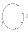
- FIG. 2 is a perspective view of the centralized power distribution member.
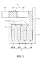
- FIG. 3 is a cross-sectional view of the centralized power distribution member taken along line III-III of FIG.
- FIG. 4 is an enlarged perspective view of the main part of the centralized power distribution member.
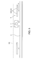
- FIG. 5 is a plan view of the centralized power distribution member before bending.
- FIG. 6 is a perspective view of a central power distribution member according to another embodiment of the present invention.
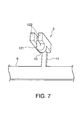
- FIG. FIG. 7 is a perspective view from the other direction of the centralized power distribution member main part according to another embodiment of the present invention.
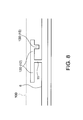
- FIG. 8 is a plan view of the centralized power distribution member prior to folding according to another embodiment of the present invention.
- the U-phase, V-phase, and W-phase bus bars 6 are connected to the power supply wiring of each phase via the bus bar strong electric terminal 5 fixed to the holding member 2.
- each coil connection terminal 3 includes an upright portion 11 extending parallel to the central axis from the bus bar 6 and a pair of arms 12 extending from the upright portion 11 toward the central axis.
- the pair of arms 12 includes a base 12A, a narrowed portion 12B, and a locking portion 12C.
- the coil connection terminal 3 is formed integrally with the bus bar strong electric terminal 5 in advance to the bus bar 6 by cutting out the band-like member 100. That is, as shown in the drawing, wing portions 120 and rising portions 11 constituting the pair of arms 12 are cut out in a shape that protrudes from the bus bar 6 in a substantially T-shape.
- the bus bar high voltage terminals 5 are also cut out so as to protrude in the same direction.
- the bus bar 6 in which the busper strong electric terminal 5 and the plurality of coil connection terminals 3 are integrally formed in advance is bent into a cylindrical shape and fixed to the tubular groove of the holding member 2.
- the busper strong electric terminal 5 is bent 90 degrees toward the central axis of the bus bar 6.
- the bolt holes 7 overlap the screw holes formed at the predetermined positions of the holding member 2, and the bus bars 6 are positioned on the holding member 2 by the bolts passed through the bolt holes 7.
- a concentrated power distribution member composed of the bus bar 6, the bus bar strong electric terminal 5 and the plurality of coil connection terminals 3 integrally formed is prepared for each of the U phase, V phase and W phase, Secure in the corresponding annular groove of. Also.
- a concentrated power distribution member composed of the bus bar 6 and the plurality of coil connection terminals 3 is prepared for the intermediate phase, and fixed to the corresponding annular groove of the holding member 2.
- the length of the pair of arms 12 differs depending on the position of the tubular groove in the holding member 2. As the concentrated power distribution member disposed in the annular groove closer to the outer periphery of the holding member 2, the distance to the coil increases. Therefore, with regard to the concentrated power distribution member disposed in the annular groove near the outer periphery of the holding member 2, the arm 12, in particular, the base 12A of the arm 12 is set long.
- the power distribution unit 1 is fixed to the casing of the motor by the bolts passing through the mounting bosses 4.
- the locking of the coil winding end to the locking portion 12C is performed as follows. That is, in a state in which the end of the winding is guided to the inside of the U-shaped planar locking portion 12C, electrodes are connected to both outer sides of the bifurcated tip 122, and a voltage is applied. The current passes through the proximal end 121 of the locking portion 12C, and generates heat due to the electrical resistance of the proximal end 121. This heat is transferred to the bifurcated tip 122 and melts the coating on the winding ends. The uncoated winding is welded to the bifurcated tip 122 in this manner. This process is called fusing.
- the pair of wing portions 120 extending in both sides is formed in advance in the upstanding portion 11 extending in the rotational axis direction of the motor from the bus bar 6, and the wing portion 120 is bent into a cylindrical shape.
- a pair of arms 12 are formed by bending from a bending line parallel to the central axis of the processed bus bar 6 toward the central axis. Further, a locking portion 12C at the end of the winding is provided at the tip of the pair of arms 12.
- the narrow portion 12B and the proximal end 121 of the locking portion 12C are formed by caulking in the middle of the pair of arms 12, the locking portion 12C for locking the end portion of the winding can be easily formed.
- the concentrated power distribution member including the bus bar 6 and the plurality of coil connection terminals 3 is formed by cutting out the single strip member 100, the concentrated power distribution member can be formed inexpensively.
- the arm 12 is shown in FIG. As shown in FIG. 5, the wing portion 120 is present as a wing portion 120 protruding laterally from the rising portion 11. Therefore, it is not necessary to widen the width of the strip member 100 for forming the arm 12, which also has a preferable effect of reducing the manufacturing cost of the centralized power distribution member.
- FIG. Referring to 6 and 7, the concentrated power distribution member according to this embodiment is provided with a bending portion 15 in one arm 12 of the coil connection terminal 3.
- the crimping step for forming the narrowed portion 12B is not necessary. Further, the projection 150 for the bent portion 15 is formed from the wing portion 120 toward the bus bar 6 when the band-like member 100 is cut out to form the concentrated power distribution member. Therefore, the bent portion 15 can be formed without increasing the width of the strip member 100.
Landscapes
- Engineering & Computer Science (AREA)
- Power Engineering (AREA)
- Insulation, Fastening Of Motor, Generator Windings (AREA)
- Windings For Motors And Generators (AREA)
Abstract
Priority Applications (4)
| Application Number | Priority Date | Filing Date | Title |
|---|---|---|---|
| CN201380011261.7A CN104137393B (zh) | 2012-02-27 | 2013-02-26 | 集中绕组电动机用的集中配电部件 |
| EP13755074.5A EP2822152B1 (fr) | 2012-02-27 | 2013-02-26 | Élément de distribution de puissance pour moteur avec bobinage concentré |
| US14/379,607 US9484782B2 (en) | 2012-02-27 | 2013-02-26 | Concentrated power-distribution member for concentrated winding motor |
| JP2014502239A JP5773057B2 (ja) | 2012-02-27 | 2013-02-26 | 集中巻モータ用の集中配電部材 |
Applications Claiming Priority (2)
| Application Number | Priority Date | Filing Date | Title |
|---|---|---|---|
| JP2012040256 | 2012-02-27 | ||
| JP2012-040256 | 2012-02-27 |
Publications (2)
| Publication Number | Publication Date |
|---|---|
| WO2013129377A1 true WO2013129377A1 (fr) | 2013-09-06 |
| WO2013129377A9 WO2013129377A9 (fr) | 2013-10-24 |
Family
ID=49082574
Family Applications (1)
| Application Number | Title | Priority Date | Filing Date |
|---|---|---|---|
| PCT/JP2013/054902 Ceased WO2013129377A1 (fr) | 2012-02-27 | 2013-02-26 | Élément de distribution d'électricité concentré, et procédé de fabrication de celui-ci |
Country Status (5)
| Country | Link |
|---|---|
| US (1) | US9484782B2 (fr) |
| EP (1) | EP2822152B1 (fr) |
| JP (1) | JP5773057B2 (fr) |
| CN (1) | CN104137393B (fr) |
| WO (1) | WO2013129377A1 (fr) |
Cited By (5)
| Publication number | Priority date | Publication date | Assignee | Title |
|---|---|---|---|---|
| JP2015195686A (ja) * | 2014-03-31 | 2015-11-05 | 本田技研工業株式会社 | 回転電機のステータ |
| US20150381002A1 (en) * | 2013-02-22 | 2015-12-31 | Sumitomo Wiring Systems., Ltd. | Centralized power distribution member for motor |
| JP2016201858A (ja) * | 2015-04-07 | 2016-12-01 | 日産自動車株式会社 | バスリングの製造方法及びバスリング |
| WO2017033339A1 (fr) * | 2015-08-27 | 2017-03-02 | 日産自動車株式会社 | Procédé de fabrication d'élément de borne, procédé de connexion d'élément de borne et d'élément conducteur, élément de borne, et élément de câblage |
| WO2019065944A1 (fr) * | 2017-09-28 | 2019-04-04 | 日本電産株式会社 | Moteur et procédé de fabrication de moteur |
Families Citing this family (11)
| Publication number | Priority date | Publication date | Assignee | Title |
|---|---|---|---|---|
| JP6073702B2 (ja) * | 2013-02-22 | 2017-02-01 | 住友電装株式会社 | モータの集中配電部材 |
| JP6262163B2 (ja) * | 2014-03-14 | 2018-01-17 | サンコール株式会社 | バスリングユニット |
| DE102015208186B4 (de) * | 2015-05-04 | 2023-06-07 | Zf Friedrichshafen Ag | Stator für eine elektrische Maschine mit einer vergossenen Verschaltungseinrichtung und elektrische Maschine mit einem solchen Stator |
| DE102016209523A1 (de) | 2016-06-01 | 2017-12-07 | Zf Friedrichshafen Ag | Stator einer elektrischen Maschine mit einer Verschaltungseinrichtung für Statorspulen und elektrische Maschine mit einem derartigen Stator |
| DE102016224542A1 (de) * | 2016-12-08 | 2018-06-14 | Bayerische Motoren Werke Aktiengesellschaft | Schaltring für einen Stator einer elektrischen Rotationsmaschine |
| DE102018102033A1 (de) * | 2018-01-30 | 2019-08-01 | Ebm-Papst St. Georgen Gmbh & Co. Kg | Statorvorrichtung mit Verschalt-Endscheibe für einen Elektromotor und Verwendung der Statorvorrichtung |
| DE102020000232A1 (de) * | 2020-01-16 | 2021-07-22 | Wieland-Werke Aktiengesellschaft | Kontakteinrichtung eines Stators, Stator und elektrische Maschine |
| JP7441072B2 (ja) * | 2020-02-25 | 2024-02-29 | 株式会社Subaru | ステータ |
| US11626766B2 (en) * | 2020-05-22 | 2023-04-11 | Hitachi Astemo, Ltd. | Power connection with overmolded axially adjusted connecting rings |
| KR102488606B1 (ko) * | 2020-07-21 | 2023-01-13 | 현대모비스 주식회사 | 모터용 버스바 유닛 |
| JP2024142040A (ja) * | 2023-03-29 | 2024-10-10 | 愛知電機株式会社 | 電動機 |
Citations (4)
| Publication number | Priority date | Publication date | Assignee | Title |
|---|---|---|---|---|
| FR2780212A1 (fr) * | 1998-06-19 | 1999-12-24 | Mannesmann Sachs Ag | Moteur electrique comprenant un agencement de liaison |
| JP2008312393A (ja) * | 2007-06-15 | 2008-12-25 | Asmo Co Ltd | バスバー装置及びブラシレスモータ |
| JP2009027838A (ja) * | 2007-07-19 | 2009-02-05 | Toyota Motor Corp | 電動機のステータに用いられる接続線、その接続線を備えたステータおよびその接続線の曲げ方法 |
| JP2010141953A (ja) | 2008-12-09 | 2010-06-24 | Nissan Motor Co Ltd | 集中巻モータ用の集中配電部材 |
Family Cites Families (4)
| Publication number | Priority date | Publication date | Assignee | Title |
|---|---|---|---|---|
| JPH06233483A (ja) * | 1993-01-29 | 1994-08-19 | Honda Motor Co Ltd | ステータに於けるコイル巻線の結線構造 |
| US7806711B2 (en) * | 2009-02-27 | 2010-10-05 | American Power Conversion Corporation | Electrical connector |
| KR101146447B1 (ko) * | 2010-11-22 | 2012-05-18 | 뉴모텍(주) | 작업성이 향상된 연결탭 구조를 갖는 버스바 |
| JP5991172B2 (ja) * | 2012-06-07 | 2016-09-14 | 日立金属株式会社 | 電動機の製造方法 |
-
2013
- 2013-02-26 EP EP13755074.5A patent/EP2822152B1/fr not_active Not-in-force
- 2013-02-26 US US14/379,607 patent/US9484782B2/en not_active Expired - Fee Related
- 2013-02-26 WO PCT/JP2013/054902 patent/WO2013129377A1/fr not_active Ceased
- 2013-02-26 JP JP2014502239A patent/JP5773057B2/ja not_active Expired - Fee Related
- 2013-02-26 CN CN201380011261.7A patent/CN104137393B/zh not_active Expired - Fee Related
Patent Citations (4)
| Publication number | Priority date | Publication date | Assignee | Title |
|---|---|---|---|---|
| FR2780212A1 (fr) * | 1998-06-19 | 1999-12-24 | Mannesmann Sachs Ag | Moteur electrique comprenant un agencement de liaison |
| JP2008312393A (ja) * | 2007-06-15 | 2008-12-25 | Asmo Co Ltd | バスバー装置及びブラシレスモータ |
| JP2009027838A (ja) * | 2007-07-19 | 2009-02-05 | Toyota Motor Corp | 電動機のステータに用いられる接続線、その接続線を備えたステータおよびその接続線の曲げ方法 |
| JP2010141953A (ja) | 2008-12-09 | 2010-06-24 | Nissan Motor Co Ltd | 集中巻モータ用の集中配電部材 |
Non-Patent Citations (1)
| Title |
|---|
| See also references of EP2822152A4 |
Cited By (11)
| Publication number | Priority date | Publication date | Assignee | Title |
|---|---|---|---|---|
| US20150381002A1 (en) * | 2013-02-22 | 2015-12-31 | Sumitomo Wiring Systems., Ltd. | Centralized power distribution member for motor |
| US9819240B2 (en) * | 2013-02-22 | 2017-11-14 | Sumitomo Wiring Systems, Ltd. | Centralized power distribution member for motor with detachable auxiliary holder |
| JP2015195686A (ja) * | 2014-03-31 | 2015-11-05 | 本田技研工業株式会社 | 回転電機のステータ |
| JP2016201858A (ja) * | 2015-04-07 | 2016-12-01 | 日産自動車株式会社 | バスリングの製造方法及びバスリング |
| WO2017033339A1 (fr) * | 2015-08-27 | 2017-03-02 | 日産自動車株式会社 | Procédé de fabrication d'élément de borne, procédé de connexion d'élément de borne et d'élément conducteur, élément de borne, et élément de câblage |
| JPWO2017033339A1 (ja) * | 2015-08-27 | 2018-04-26 | 日産自動車株式会社 | 端子部材の製造方法、端子部材と導電部材の接続方法、端子部材、および配電部材 |
| RU2683240C1 (ru) * | 2015-08-27 | 2019-03-27 | Ниссан Мотор Ко., Лтд. | Способ изготовления элемента контактного вывода, способ соединения элемента контактного вывода и проводящего элемента, элемент контактного вывода и элемент межсоединений |
| US10263378B2 (en) | 2015-08-27 | 2019-04-16 | Nissan Motor Co., Ltd. | Method for manufacturing terminal member, method for connecting terminal member and conductive member, terminal member, and wiring member |
| WO2019065944A1 (fr) * | 2017-09-28 | 2019-04-04 | 日本電産株式会社 | Moteur et procédé de fabrication de moteur |
| CN110999039A (zh) * | 2017-09-28 | 2020-04-10 | 日本电产株式会社 | 马达和马达的制造方法 |
| CN110999039B (zh) * | 2017-09-28 | 2022-04-22 | 日本电产株式会社 | 马达和马达的制造方法 |
Also Published As
| Publication number | Publication date |
|---|---|
| US20150008775A1 (en) | 2015-01-08 |
| JPWO2013129377A1 (ja) | 2015-07-30 |
| EP2822152B1 (fr) | 2016-09-28 |
| CN104137393B (zh) | 2016-11-09 |
| US9484782B2 (en) | 2016-11-01 |
| WO2013129377A9 (fr) | 2013-10-24 |
| EP2822152A4 (fr) | 2016-01-27 |
| JP5773057B2 (ja) | 2015-09-02 |
| EP2822152A1 (fr) | 2015-01-07 |
| CN104137393A (zh) | 2014-11-05 |
Similar Documents
| Publication | Publication Date | Title |
|---|---|---|
| WO2013129377A9 (fr) | Élément de distribution d'électricité concentré, et procédé de fabrication de celui-ci | |
| JP6204188B2 (ja) | 回転電機のステータ | |
| US10250093B2 (en) | Stator for rotary electric machine and method for manufacturing the same | |
| JP5930801B2 (ja) | 車載用モータ、及びそれを用いた電動パワーステアリング装置 | |
| JP6286129B2 (ja) | バスバーユニット | |
| US9318814B2 (en) | Wire connection member, wire connection structure and annular power distribution member | |
| JP5232941B1 (ja) | 誘導モータ用のバスバー | |
| US8508088B2 (en) | Wiring component for motor coil | |
| US20140354094A1 (en) | Rotary electric machine | |
| JP5743162B2 (ja) | 固定子および回転電機 | |
| JP2008253063A (ja) | モータ用ステータ及びその製造方法 | |
| JP5991261B2 (ja) | 電動機の製造方法 | |
| WO2013179476A1 (fr) | Machine électrique tournante, stator pour faire tourner une machine électrique et véhicule | |
| JP2019068494A (ja) | 回転電機ステータ、及び、その製造方法 | |
| BR102013004972B1 (pt) | Máquina giratória elétrica, e, método de fabricar os segmentos de condutor elétrico | |
| JP2015149863A (ja) | 回転電機のステータ | |
| US8659201B2 (en) | Stator for electric rotating machine | |
| JP2019050670A (ja) | ステータ構造およびレゾルバ | |
| JP6350543B2 (ja) | 集配電リング及び電動機 | |
| JP5909790B2 (ja) | 回転電機、回転電機用ステータおよび車両 | |
| JP2012157225A (ja) | 絶縁部材およびステータ | |
| KR20230029766A (ko) | 전기 기계용 고정자 | |
| JP6308680B2 (ja) | バスリングの製造方法 | |
| JP2006191733A (ja) | 回転電機の巻線接続構造 | |
| JP2024084501A (ja) | 中性線、及び回転電機 |
Legal Events
| Date | Code | Title | Description |
|---|---|---|---|
| 121 | Ep: the epo has been informed by wipo that ep was designated in this application |
Ref document number: 13755074 Country of ref document: EP Kind code of ref document: A1 |
|
| WWE | Wipo information: entry into national phase |
Ref document number: 14379607 Country of ref document: US |
|
| ENP | Entry into the national phase |
Ref document number: 2014502239 Country of ref document: JP Kind code of ref document: A |
|
| NENP | Non-entry into the national phase |
Ref country code: DE |
|
| REEP | Request for entry into the european phase |
Ref document number: 2013755074 Country of ref document: EP |
|
| WWE | Wipo information: entry into national phase |
Ref document number: 2013755074 Country of ref document: EP |