WO2013129409A1 - 遠心流体機械の吸気管構造 - Google Patents
遠心流体機械の吸気管構造 Download PDFInfo
- Publication number
- WO2013129409A1 WO2013129409A1 PCT/JP2013/054988 JP2013054988W WO2013129409A1 WO 2013129409 A1 WO2013129409 A1 WO 2013129409A1 JP 2013054988 W JP2013054988 W JP 2013054988W WO 2013129409 A1 WO2013129409 A1 WO 2013129409A1
- Authority
- WO
- WIPO (PCT)
- Prior art keywords
- intake pipe
- pipe structure
- transition portion
- impeller
- flow
- Prior art date
- Legal status (The legal status is an assumption and is not a legal conclusion. Google has not performed a legal analysis and makes no representation as to the accuracy of the status listed.)
- Ceased
Links
Images




Classifications
-
- F—MECHANICAL ENGINEERING; LIGHTING; HEATING; WEAPONS; BLASTING
- F04—POSITIVE - DISPLACEMENT MACHINES FOR LIQUIDS; PUMPS FOR LIQUIDS OR ELASTIC FLUIDS
- F04D—NON-POSITIVE-DISPLACEMENT PUMPS
- F04D29/00—Details, component parts, or accessories
- F04D29/40—Casings; Connections of working fluid
- F04D29/42—Casings; Connections of working fluid for radial or helico-centrifugal pumps
- F04D29/4206—Casings; Connections of working fluid for radial or helico-centrifugal pumps especially adapted for elastic fluid pumps
- F04D29/4213—Casings; Connections of working fluid for radial or helico-centrifugal pumps especially adapted for elastic fluid pumps suction ports
-
- F—MECHANICAL ENGINEERING; LIGHTING; HEATING; WEAPONS; BLASTING
- F02—COMBUSTION ENGINES; HOT-GAS OR COMBUSTION-PRODUCT ENGINE PLANTS
- F02M—SUPPLYING COMBUSTION ENGINES IN GENERAL WITH COMBUSTIBLE MIXTURES OR CONSTITUENTS THEREOF
- F02M35/00—Combustion-air cleaners, air intakes, intake silencers, or induction systems specially adapted for, or arranged on, internal-combustion engines
- F02M35/10—Air intakes; Induction systems
- F02M35/10091—Air intakes; Induction systems characterised by details of intake ducts: shapes; connections; arrangements
- F02M35/10124—Ducts with special cross-sections, e.g. non-circular cross-section
-
- F—MECHANICAL ENGINEERING; LIGHTING; HEATING; WEAPONS; BLASTING
- F02—COMBUSTION ENGINES; HOT-GAS OR COMBUSTION-PRODUCT ENGINE PLANTS
- F02M—SUPPLYING COMBUSTION ENGINES IN GENERAL WITH COMBUSTIBLE MIXTURES OR CONSTITUENTS THEREOF
- F02M35/00—Combustion-air cleaners, air intakes, intake silencers, or induction systems specially adapted for, or arranged on, internal-combustion engines
- F02M35/10—Air intakes; Induction systems
- F02M35/1015—Air intakes; Induction systems characterised by the engine type
- F02M35/10157—Supercharged engines
-
- F—MECHANICAL ENGINEERING; LIGHTING; HEATING; WEAPONS; BLASTING
- F04—POSITIVE - DISPLACEMENT MACHINES FOR LIQUIDS; PUMPS FOR LIQUIDS OR ELASTIC FLUIDS
- F04D—NON-POSITIVE-DISPLACEMENT PUMPS
- F04D17/00—Radial-flow pumps, e.g. centrifugal pumps; Helico-centrifugal pumps
- F04D17/08—Centrifugal pumps
- F04D17/10—Centrifugal pumps for compressing or evacuating
-
- F—MECHANICAL ENGINEERING; LIGHTING; HEATING; WEAPONS; BLASTING
- F04—POSITIVE - DISPLACEMENT MACHINES FOR LIQUIDS; PUMPS FOR LIQUIDS OR ELASTIC FLUIDS
- F04D—NON-POSITIVE-DISPLACEMENT PUMPS
- F04D29/00—Details, component parts, or accessories
- F04D29/40—Casings; Connections of working fluid
- F04D29/42—Casings; Connections of working fluid for radial or helico-centrifugal pumps
- F04D29/44—Fluid-guiding means, e.g. diffusers
- F04D29/441—Fluid-guiding means, e.g. diffusers especially adapted for elastic fluid pumps
-
- F—MECHANICAL ENGINEERING; LIGHTING; HEATING; WEAPONS; BLASTING
- F02—COMBUSTION ENGINES; HOT-GAS OR COMBUSTION-PRODUCT ENGINE PLANTS
- F02B—INTERNAL-COMBUSTION PISTON ENGINES; COMBUSTION ENGINES IN GENERAL
- F02B39/00—Component parts, details, or accessories relating to, driven charging or scavenging pumps, not provided for in groups F02B33/00 - F02B37/00
- F02B39/16—Other safety measures for, or other control of, pumps
-
- F—MECHANICAL ENGINEERING; LIGHTING; HEATING; WEAPONS; BLASTING
- F05—INDEXING SCHEMES RELATING TO ENGINES OR PUMPS IN VARIOUS SUBCLASSES OF CLASSES F01-F04
- F05D—INDEXING SCHEME FOR ASPECTS RELATING TO NON-POSITIVE-DISPLACEMENT MACHINES OR ENGINES, GAS-TURBINES OR JET-PROPULSION PLANTS
- F05D2220/00—Application
- F05D2220/40—Application in turbochargers
-
- F—MECHANICAL ENGINEERING; LIGHTING; HEATING; WEAPONS; BLASTING
- F05—INDEXING SCHEMES RELATING TO ENGINES OR PUMPS IN VARIOUS SUBCLASSES OF CLASSES F01-F04
- F05D—INDEXING SCHEME FOR ASPECTS RELATING TO NON-POSITIVE-DISPLACEMENT MACHINES OR ENGINES, GAS-TURBINES OR JET-PROPULSION PLANTS
- F05D2250/00—Geometry
- F05D2250/50—Inlet or outlet
- F05D2250/51—Inlet
-
- Y—GENERAL TAGGING OF NEW TECHNOLOGICAL DEVELOPMENTS; GENERAL TAGGING OF CROSS-SECTIONAL TECHNOLOGIES SPANNING OVER SEVERAL SECTIONS OF THE IPC; TECHNICAL SUBJECTS COVERED BY FORMER USPC CROSS-REFERENCE ART COLLECTIONS [XRACs] AND DIGESTS
- Y02—TECHNOLOGIES OR APPLICATIONS FOR MITIGATION OR ADAPTATION AGAINST CLIMATE CHANGE
- Y02T—CLIMATE CHANGE MITIGATION TECHNOLOGIES RELATED TO TRANSPORTATION
- Y02T10/00—Road transport of goods or passengers
- Y02T10/10—Internal combustion engine [ICE] based vehicles
- Y02T10/12—Improving ICE efficiencies
Definitions
- the present invention relates to an intake pipe structure of a centrifugal compressor, a mixed flow compressor, a centrifugal blower, and a mixed flow blower (hereinafter collectively referred to as a centrifugal fluid machine) which is one of fluid machines.
- Turbochargers and turbo refrigerators mounted on vehicles and ships are equipped with an impeller rotating at high speed, and use a centrifugal compressor that pressurizes fluid using centrifugal force.
- this centrifugal compressor requires a wide operating range, when the flow rate of the fluid introduced to the centrifugal compressor decreases, the discharge pressure pulsates to cause surging in which the operating state becomes unstable, which results in an operation limit. . Therefore, in order to secure a wide operating range in a centrifugal compressor, it is necessary to reduce the critical flow rate at which surging occurs.
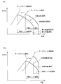
- FIG. 13 (a) is a graph showing a change in the performance characteristic of the compressor when the fluid introduced to the impeller is swirled in the forward direction when the rotation speed is fixed.
- FIG. 13 (a) when the fluid guided to the impeller is turned forward, the surge line moves to the left side of the graph, and the critical flow rate at which surging occurs decreases.
- the maximum flow rate is also reduced, so the operating range itself can not be expanded.
- FIG. 13 (b) is a graph showing a change in performance characteristics of the compressor when the fluid led to the impeller is reversely swirled when the rotation speed is fixed.
- the performance curve moves to the upper right side of the graph, and the pressure ratio is improved.
- the surge line is also moved to the right of the graph, and the operating range itself is narrowed.
- Patent Document 1 in a centrifugal compressor of a turbocharger for an automobile, a variable mechanism including an air deflection vane is operated by an actuator or the like to reversely swirl the fluid guided to the impeller at a large flow rate and at a small flow rate.
- a pre-turn generator is disclosed that can be turned forward.
- the pressure ratio is improved by guiding the reverse swirl flow at the large flow rate, and the forward swirl flow is introduced at the small flow rate. Can avoid surging.
- the maximum flow rate of the operating range is not reduced, a wide operating range can be secured.
- Patent No. 4446661 gazette
- the pre-swing generator described in Patent Document 1 described above is a mechanical pre-swing generator that operates a variable mechanism by an actuator or the like, and there is a problem in that the size and cost of the apparatus are increased.
- turbochargers for automobiles there is a strong demand for downsizing and cost reduction of the apparatus, and it is not practical to adopt mechanical means.
- the present invention is an invention made in view of such a problem of the prior art, and reverses the flow of the fluid conducted to the impeller at a large flow rate by devising the shape of the intake pipe without using mechanical means. It is an object of the present invention to provide an intake pipe structure of a centrifugal fluid machine which can be swirled to improve a pressure ratio and forward swirl at a small flow rate to avoid surging and secure a wide operation range.
- the intake pipe structure of the centrifugal fluid machine according to the present invention is a centrifugal fluid machine having an impeller mounted on a rotary shaft and a housing for housing the impeller, substantially in a direction orthogonal to the axial direction of the rotary shaft.
- An intake pipe structure for guiding a flowing fluid to a rotation center of an impeller housed in the housing through a suction pipe portion of the housing protruding in the axial direction of the rotation shaft,
- the inflow portion extending in a direction substantially orthogonal to the axial direction of the rotation shaft; and a transition portion connecting the inflow portion and the suction pipe portion of the housing,
- There is a virtual plane which is orthogonal to the axial direction of the rotation axis and passes through the flow passage cross section of the inflow portion, and the intersection with the axial line of the rotation axis is located inside the transition portion It is characterized in that it is configured to
- the intake pipe structure of the centrifugal fluid machine of the present invention is an intake pipe structure for guiding a fluid flowing in a direction substantially orthogonal to the axial direction of the rotation shaft to the rotation center of the impeller, as described above And an imaginary plane configured to be orthogonal to the axial direction of the rotation axis and pass through the flow passage cross section of the inflow portion, and the intersection point with the axial direction line of the rotation axis is located inside the transition portion It is configured.
- the intake pipe structure of the present invention thus configured has a shape that is sharply bent in front of the suction pipe portion of the housing.
- the flow (main flow) of the fluid from the inflow portion to the suction pipe portion of the housing through the transition portion is rapidly changed in front of the suction pipe portion to cause disturbance in the main flow.
- the pressure ratio is high when the flow rate is small, the fluid to which the swirling flow is given by the impeller flows back to the upstream of the impeller, and the reverse flow flows into the transition part, and the flow is disturbed to the mainstream It produces a swirling flow.
- the pressure ratio is low, and the flow velocity of the main stream flowing through the transition part is also high, so that a swirling flow due to the reverse flow does not occur.
- the shape of the intake pipe structure in a front view when the rotation center of the impeller is viewed from the front is in the direction opposite to the rotation direction of the impeller from the inflow portion side toward the transition portion side bent. That is, when the impeller is rotating in the clockwise direction in front view, it is bent to the left from the inflow side to the transition portion side, and when the impeller is rotating in the counterclockwise direction. Is bent to the right from the inflow side to the transition side.
- the intake pipe structure As described above, if the intake pipe structure is bent in the direction opposite to the rotational direction of the impeller, the main flow through the intake pipe structure becomes a swirling flow in reverse rotation with respect to the rotational direction of the impeller at a large flow rate. Since it flows into the impeller, the pressure ratio can be improved. On the other hand, when the flow rate is small, the influence of the above-described backflow is stronger, and the fluid guided to the impeller remains in the forward swirling flow. Therefore, according to such an intake pipe structure of the present invention, when the flow rate is large, the fluid conducted to the impeller is reversely swirled to improve the pressure ratio, and when the flow rate is small, the fluid conducted to the impeller is forward swirled. It is possible to avoid surging. In addition, a wide operating range can be secured without reducing the maximum flow rate of the operating range.
- the entire length of the transition portion is L
- the flow passage cross-sectional area of one end of the transition portion connected to the inflow portion is A1
- the flow passage cross-sectional area of the other end of the transition portion connected to the suction pipe portion Where at least a partial section of the transition portion satisfies the relationship of the following formula (1), where A2 is a channel cross-sectional area of the transition portion at a position separated by a distance L1 from one end of the transition portion as A3. It is desirable to be configured.
- a large section of the flow passage cross section is formed between one end and the other end of the transition portion, so that the backflow easily reaches the upstream side of the transition portion at a small flow rate. A stronger forward swirling flow can be generated with respect to the main flow.
- the flow passage cross-section of a partial section of the transition portion is formed in a non-circular shape, it is easier for the backflow to reach the upstream side of the transition portion at a small flow rate. It is preferable because a swirl flow in the direction is generated.
- the intake pipe structure of the centrifugal fluid machine of the present invention thus configured can be particularly suitably used as a centrifugal compressor of an automotive turbocharger.
- the fluid guided to the impeller is reversely rotated at a large flow rate to improve the pressure ratio, and the fluid guided to the impeller is forwardly rotated at a small flow rate, without using mechanical means. It is possible to provide an intake pipe structure of a centrifugal fluid machine that can avoid surging and secure a wide operating range.
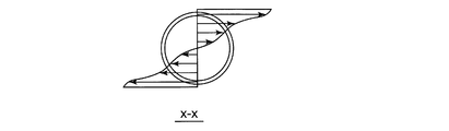
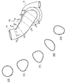
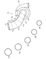
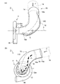
- FIG. 5 is a view showing velocity vector distribution of fluid in the x-x cross section of FIG. 4 (a). It is a schematic diagram showing the flow of the fluid in the intake pipe structure of the present invention. It is the graph which showed the flow-path cross-sectional area of the intake pipe structure of this invention. It is a schematic diagram for demonstrating the flow-path cross section in the transition part of the intake pipe structure of this invention. It is the figure which showed each cross section of the intake pipe structure of this invention. It is the figure which showed each cross section of the intake pipe structure of a comparative example.
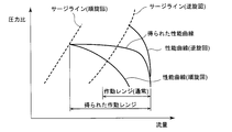
- FIG. 16 is a graph showing a change in performance characteristics of the compressor when the fluid introduced to the impeller is reversely swirled in the case where FIG. 10 is a graph showing a change in performance characteristics of the compressor when the fluid introduced to the impeller is forwardly rotated at low flow rate and the fluid introduced to the impeller is reversely rotated at high flow rate.
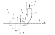
- FIG. 1 is a schematic view showing a centrifugal compressor of an automotive turbocharger to which an intake pipe structure of the present invention is applied, as one embodiment of the present invention.
- the automotive turbocharger 1 includes a compressor housing 4 (housing) containing a compressor rotor (impeller), a bearing housing 5 containing a rotation shaft, and a turbine rotor.
- the turbine housing 6 is provided.
- the compressor rotor and the turbine rotor are mounted coaxially with respect to the rotation axis, and the exhaust gas flowing into the turbine housing 6 rotates the turbine rotor, whereby the coaxially mounted compressor rotor also rotates. Is configured as.
- a suction pipe portion 4a is provided in the axial direction of the rotation shaft so as to protrude from the front surface of the compressor housing 4 (the surface viewed from the A direction in FIG. 1).
- an intake pipe structure 10 of the present invention is connected to the intake pipe portion 4a, and the intake pipe structure 10 extends in a direction substantially orthogonal to the rotation axis 3 (axial line of the rotation axis).
- An intake passage 18 is connected.
- an exhaust pipe 8 is connected to the scroll portion 4 b extended in the circumferential direction of the compressor housing 4.
- the centrifugal compressor 2 of the present embodiment is composed of the compressor housing 4, an exhaust pipe 8 and an intake pipe structure 10. Then, as the compressor rotor rotates, a fluid f such as air flowing through the intake passage 18 flows through the intake pipe structure 10, and the front surface of the compressor rotor accommodated in the compressor housing 4 via the intake pipe portion 4a. It is introduced to the
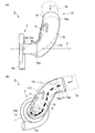
- FIG. 2A is a view showing an intake pipe structure of the present invention, in which (a) is a side view of a rotational axis viewed from the side, and (b) is a front view of a compressor rotor viewed from the front.
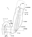
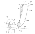
- FIG. 2B is a perspective view showing the intake pipe structure of the present invention.
- Arrows f1 and f2 in FIG. 2A indicate the flow directions of the main flow f1 and the reverse flow f2 at a small flow rate
- a two-dot chain line 110 in FIG. 2A indicates the shape of the intake pipe structure 110 in the comparative example. It is a line.
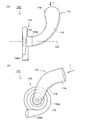
- FIG. 3A is a view showing an intake pipe structure in a comparative example, in which (a) is a side view in which the rotation axis is viewed from the side, and (b) is a front view in which the impeller is viewed from the front.
- FIG. 3B is a perspective view showing the intake pipe structure of the present invention.
- the intake pipe structure 110 of the comparative example the loss of the fluid f flowing in the direction substantially orthogonal to the rotation axis 103 is as small as possible based on the general design concept to the conventional intake pipe structure, and the compressor is The present inventors designed an intake pipe structure that can be conducted to the rotation center 112 a of the rotor 112.
- the compressor rotor 12 housed in the compressor housing 4 is housed so as to rotate clockwise in a front view about the rotation center 12a. There is.
- the inflow portion 14 extends straight in a direction substantially orthogonal to the rotation axis 3, and the flow passage cross section does not change.
- substantially orthogonal means that the crossing angle between the extending direction of the inflow portion 14 and the rotation axis 3 forms an angle close to a substantially right angle, specifically, a case where it is in the range of 75 degrees to 105 degrees. It shall be.
- one end 16 a is oriented substantially horizontally to the rotation axis 3, and the other end 16 b is oriented perpendicularly to the rotation axis 3.
- the flow passage cross section is formed such that the flow passage cross section in the middle is enlarged as described later.
- the intake pipe structure 10 of the present invention has a shape bulging out on both sides inside and outside of the curved portion in side view in side view It has become. Moreover, in front view, it has the shape which bulged inside the curved part in front view.
- the intake pipe structure 10 of the present invention is orthogonal to the rotation axis 3 and passes through the flow passage cross section of the inflow portion 14, and the intersection 22 with the rotation axis 3 is inside the transition portion 16.
- the imaginary plane 20 of FIG. 2B passes through the center 15 at the upstream end 14 a of the inlet 14.
- the intake pipe structure 110 of the comparative example as shown in FIG. 3B, it passes through the inflow cross section of the inflow portion 114 orthogonal to the rotation axis 103 and the intersection 122 with the rotation axis 103 is a transition portion
- the intersection point 122 with the rotation axis 103 is located outside the transition portion 116.
- the intake pipe structure 10 of the present invention configured as described above has a shape in which the transition portion 16 is sharply bent in front of the intake pipe portion 4 a.
- the flow of the fluid (main stream f1) flowing from the intake passage 18 and flowing from the inflow portion 14 through the transition portion 16 to the suction pipe 4a of the compressor housing 4 is The air changes rapidly in front of the suction pipe 4a, and turbulence occurs in the main flow f1.
- the pressure ratio is high when the flow rate is small as shown in FIG. 4A, the fluid flowing into the compressor housing 4 collides with the surface of the compressor rotor 12 to generate a swirling flow (backflow f2).
- FIG. 5 shows the velocity vector distribution of the fluid in the x-x cross section of FIG. 4 (a).
- the pressure ratio is low, and the flow velocity of the main flow f1 flowing through the transition section 16 is also fast, so that the swirl flow due to the backflow f2 does not occur.
- the main flow f 1 is conducted straight toward the rotation center 12 of the compressor rotor 12. That is, in the intake pipe structure 10 of the present invention, a forward swirl flow is generated in the fluid conducted to the compressor housing 4 only when the flow rate is small.
- the shape of the intake pipe structure 10 in a front view is a compressor from the inflow portion 14 side to the other end 16b side of the transition portion 16
- the rotor 12 is curved in the direction opposite to the rotational direction r, that is, in the counterclockwise direction.
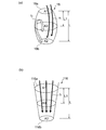
- the intake pipe structure 10 is bent in the direction opposite to the rotation direction of the compressor rotor 12, as shown schematically in FIG. 6, the intake air at the large flow rate shown in FIG.
- the main flow f 1 flowing through the pipe structure 10 flows into the compressor rotor 12 as a swirl flow reversely rotating with respect to the rotational direction r of the compressor rotor 12.
- the influence of the above-described backflow f2 is stronger, so the fluid f1 conducted to the compressor rotor 12 remains a swirling flow in the forward direction.
- the fluid guided to the compressor rotor 12 is reversely rotated at a large flow rate, and the fluid guided to the compressor rotor 12 is forwardly rotated at a small flow rate.
- An intake pipe structure 10 capable of securing a range can be provided.
- the swirling flow reverse to the rotational direction r of the compressor rotor 112 is the compressor rotor at both large flow and small flow. It flows into 112. Therefore, although the pressure ratio can be improved when the flow rate is large, surging tends to occur when the flow rate is small, and a wide operating range can not be ensured.
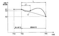
- FIG. 7 is a graph showing the flow passage cross-sectional area at each position of the intake pipe structure 10.
- L is the total length of the transition portion 16
- A1 is the flow passage cross-sectional area of one end 16a of the transition portion 16
- A2 is the flow passage cross-sectional area of the other end 16b of the transition portion 16
- A3 is the transition portion It is a flow passage cross-sectional area of the transition portion 16 at a position separated by a distance L1 from one end 16a of 16.
- the flow passage cross-sectional area A3 at a position separated from the one end 16a of the transition portion 16 by the distance L1 is formed larger than the cross-sectional area indicated by the dotted line 7 in the drawing. That is, as schematically shown in FIG. 8A, the transition portion 16 of the present invention has a barrel-shaped bulging shape in which the cross section of the flow passage between one end 16a and the other end 16b is enlarged. .
- the transition portion 116 of the comparative example as schematically shown in FIG. 8B, the flow passage cross-sectional area A1 of the one end 116a is the largest, and the flow is toward the other end 116b.
- the road cross-sectional area is uniformly reduced.
- a section in which the flow channel cross section is enlarged is formed between the one end 16a and the other end 16b, as schematically shown in FIG. 8A.
- the backflow f2 can easily reach the upstream side of the transition portion 16. As a result, a stronger forward swirl flow can be generated by the main flow f1.
- the flow passage cross section of the transition portion 16 is formed in a non-circular shape.
- the intake pipe structure 110 of the comparative example as shown in FIG. 10, not only the inflow portion 114 but also the flow passage cross section of the transition portion 116 is formed in a circular shape.
- the flow passage cross section of the transition portion 16 is formed in a non-circular shape, it flows in the transition portion 16 as compared with the case where the flow passage cross section of the transition portion 116 is formed in a circular shape as in the comparative example.
- the loss of fluid increases, and the mainstream f1 is easily disturbed by that amount. Therefore, at low flow rates, the backflow f2 can more easily reach the upstream side of the transition portion 16, and a strong forward swirl flow can be generated by the main flow f1.
- a non-circular channel cross section may not be formed in the entire section of the transition portion 16, and may be formed in at least a partial section of the transition portion 16.
- the backflow f2 easily reaches the upstream of the transition portion 16 and is stronger than the main flow f1. It is effective in generating a forward swirl flow.
- the intake pipe structure 10 of the present invention improves the compression ratio by reversing the fluid conducted to the compressor rotor 12 at a large flow rate by devising the shape of the intake pipe and the like without using mechanical means. Surging is avoided by forwardly swirling the fluid conducted to the compressor rotor 12 when the flow rate is small, and a wide operating range can be secured.
- Such an intake pipe structure 10 according to the present invention can be particularly suitably used in a turbocharger for a motor vehicle where there is a strong demand for downsizing and cost reduction of the device.
- FIG. 11A is a view showing an intake pipe structure according to another embodiment of the present invention, in which (a) is a side view of the rotational axis viewed from the side, and (b) is a front view of the compressor rotor.
- FIG. 11B is a perspective view showing an intake pipe structure according to another embodiment of the present invention. Arrows f1 and f2 in FIG. 11A indicate the flow directions of the main flow f1 and the back flow f2 at a small flow rate.
- the intake pipe structure of this another embodiment basically has the same configuration as that of the above-described embodiment, and the same configuration is denoted with the same reference numeral, and the detailed description thereof will be omitted.
- the intake pipe structure 10 of this another embodiment passes through the flow passage cross section of the inflow portion 14 at a right angle with the rotation axis 3 as shown in FIG. 11B.
- the imaginary plane 20 of FIG. 11B passes through the center 15 at the upstream end 14 a of the inflow portion 14.
- the difference is that the curved portion in the side view largely bulges out more than the embodiment described above, and as shown in FIG. 11A (a), at the small flow rate, the outer side in the side view
- the backflow f2 flows into the bulging portion.
- the backflow f2 flows into the outside of the curved portion in the front view, and the main flow f1 flows in the inside of the curved portion in the front view It is supposed to flow.
- the fluid introduced to the compressor rotor 12 is reversely swirled at a large flow rate to improve the compression ratio, as in the above-described embodiment.
- forward swirling of the fluid introduced to the compressor rotor 12 can avoid surging and secure a wide operating range.
- the flow passage cross section of the transition portion 16 satisfies the relationship of the above equation (1) at least in the section on the other end 16b side.
- the backflow f2 can easily reach at least the section satisfying the above equation (1) when the flow rate is small, so that the swirl flow stronger in the forward direction by the main flow f1 as in the embodiment described above. Can be generated.
- centrifugal-fluid machines such as a centrifugal compressor and a centrifugal blower
- an inlet pipe structure in centrifugal compressors such as a turbocharger mounted in a vehicle or a ship, and a turbo refrigerator.
Landscapes
- Engineering & Computer Science (AREA)
- Mechanical Engineering (AREA)
- General Engineering & Computer Science (AREA)
- Chemical & Material Sciences (AREA)
- Combustion & Propulsion (AREA)
- Structures Of Non-Positive Displacement Pumps (AREA)
- Supercharger (AREA)
Description
本発明は、流体機械の一つである遠心圧縮機、斜流圧縮機、遠心送風機および斜流送風機(以下、これらを総称して遠心流体機械と称する)の吸気管構造に関する。
車両や船舶に搭載されるターボチャージャやターボ冷凍機には、高速で回転する羽根車を備え、遠心力を利用して流体を昇圧する遠心圧縮機が用いられる。この遠心圧縮機には広い作動レンジが求められるが、遠心圧縮機に導流される流体の流量が減少すると吐出圧力が脈動して運転状態が不安定になるサージングが発生し、作動限界となる。よって、遠心圧縮機において広い作動レンジを確保するためには、サージングが発生する限界流量を低減する必要がある。
上述した限界流量を低減するには、図13(a)に示したように、羽根車に導流する流体を羽根車の回転方向と同じ方向に旋回(順旋回)させることが有効である。ここで図13(a)は、回転数を一定にした場合において、羽根車に導流する流体を順旋回させた場合の圧縮機の性能特性の変化を示したグラフである。この図13(a)からも分かるように、羽根車に導流する流体を順旋回させると、サージラインがグラフの左側に移動し、サージングが発生する限界流量が小さくなる。しかしながら、羽根車に導流する流体を順旋回させると最大流量も低下するため、作動レンジ自体を広げることはできない。
一方、大流量時においては高い圧力比が求められる。高い圧力比を実現するためには、図13(b)に示したように、羽根車に導流する流体を羽根車の回転方向と反対方向に旋回(逆旋回)させることが有効である。ここで図13(b)は、回転数を一定にした場合において、羽根車に導流する流体を逆旋回させた場合の圧縮機の性能特性の変化を示したグラフである。この図13(b)からも分かるように、羽根車に導流する流体を逆旋回させると、性能曲線がグラフの右上側に移動し、圧力比が向上する。しかしながら、羽根車に導流する流体を逆旋回させると、サージラインもグラフの右側に移動するため、作動レンジ自体は狭くなってしまう。
特許文献1には、自動車用ターボチャージャの遠心圧縮機において、空気偏向ベーンからなる可変機構をアクチュエータ等によって作動させることで、羽根車に導流する流体を大流量時には逆旋回させ、小流量時には順旋回させることができる事前旋回発生装置が開示されている。この特許文献1の事前旋回発生装置によれば、図14に示したように、大流量時には逆旋回流を導流することで圧力比を向上させ、小流量時には順旋回流を導流することでサージングを回避することができる。また、作動レンジの最大流量も低下しないため、広い作動レンジを確保することができる。
しかしながら、上述した特許文献1の事前旋回発生装置は、アクチュエータ等によって可変機構を操作する機械式の事前旋回発生装置であり、装置の大型化や高コスト化を招来するとの問題がある。特に自動車用のターボチャージャにおいては、装置の小型化、低コスト化への要求が強く、機械的手段を採用するのは現実的ではない。
本発明は、このような従来技術の課題に鑑みなされた発明であって、機械的手段によることなく、吸気管の形状等を工夫することで、羽根車に導流する流体を大流量時には逆旋回させて圧力比を向上させ、小流量時には順旋回させることでサージングを回避し、且つ広い作動レンジを確保できる遠心流体機械の吸気管構造を提供することを目的とする。
本発明は、上述したような従来技術における課題及び目的を達成するために発明されたものであって、
本発明の遠心流体機械の吸気管構造は、回転軸に取り付けられた羽根車と、該羽根車を収容するハウジングとを有する遠心流体機械において、前記回転軸の軸方向に対して略直交方向に流れる流体を、前記回転軸の軸方向に突設する前記ハウジングの吸入管部を介して、前記ハウジングに収容されている羽根車の回転中心に導流するための吸気管構造であって、
前記回転軸の軸方向に対して略直交方向に延伸する流入部と、該流入部と前記ハウジングの吸入管部とを接続する遷移部とを備え、
前記回転軸の軸方向と直交し且つ前記流入部の流路断面を通過するとともに、前記回転軸の軸方向線との交点が前記遷移部の内部に位置するように構成された仮想平面が存在するように構成されていることを特徴とする。
本発明の遠心流体機械の吸気管構造は、回転軸に取り付けられた羽根車と、該羽根車を収容するハウジングとを有する遠心流体機械において、前記回転軸の軸方向に対して略直交方向に流れる流体を、前記回転軸の軸方向に突設する前記ハウジングの吸入管部を介して、前記ハウジングに収容されている羽根車の回転中心に導流するための吸気管構造であって、
前記回転軸の軸方向に対して略直交方向に延伸する流入部と、該流入部と前記ハウジングの吸入管部とを接続する遷移部とを備え、
前記回転軸の軸方向と直交し且つ前記流入部の流路断面を通過するとともに、前記回転軸の軸方向線との交点が前記遷移部の内部に位置するように構成された仮想平面が存在するように構成されていることを特徴とする。
本発明の遠心流体機械の吸気管構造は、回転軸の軸方向に対して略直交方向に流れる流体を、羽根車の回転中心に導流するための吸気管構造であって、上述したように、回転軸の軸方向と直交し且つ流入部の流路断面を通過するとともに、回転軸の軸方向線との交点が遷移部の内部に位置するように構成された仮想平面が存在するように構成されている。このように構成される本発明の吸気管構造は、ハウジングの吸入管部の手前で急に曲がった形状となる。
このため、流入部から遷移部を通ってハウジングの吸入管部へと向かう流体の流れ(主流)が、吸入管部の手前にて急激に変化することで、この主流に乱れが生じる。この際、小流量時は圧力比が高いことから、羽根車によって旋回流が与えられた流体が羽根車上流に逆流し、この逆流が遷移部に流れ込んで、流れが乱れた主流に順方向の旋回流を生じせしめる。一方、大流量時は圧力比が低く、また遷移部を流れる主流の流速も速いことから、逆流による旋回流は発生しない。よって、このような本発明の吸気管構造によれば、羽根車に導流する流体に小流量時にのみ順方向の旋回流を生じさせることで、サージングを回避することができる。また、作動レンジの最大流量を低下させずに、広い作動レンジを確保することができる。
上記発明において、前記羽根車の回転中心を正面から視た正面視における前記吸気管構造の形状が、前記流入部側から前記遷移部側に向かって、前記羽根車の回転方向とは反対方向に曲がっている。すなわち、正面視において羽根車が時計回り方向に回転している場合には、流入部側から遷移部側に向かって左側に曲がっており、羽根車が反時計回り方向に回転している場合には、流入部側から遷移部側に向かって右側に曲がっている。
このように、吸気管構造が羽根車の回転方向とは反対方向に曲がっていれば、大流量時において、吸気管構造を流れる主流が羽根車の回転方向に対して逆回転の旋回流となって羽根車に流れ込むため、圧力比を向上させることができる。一方、小流量時では、上述した逆流の影響の方が強く、羽根車に導流される流体は順方向の旋回流のままとなる。よって、このような本発明の吸気管構造によれば、大流量時には羽根車に導流する流体を逆旋回させて圧力比を向上させ、小流量時には羽根車に導流する流体を順旋回させることでサージングを回避することができる。また、作動レンジの最大流量を低下させずに、広い作動レンジを確保することができる。
また上記発明において、前記遷移部の全長をL、前記流入部と接続する前記遷移部の一端の流路断面積をA1、前記吸入管部と接続する前記遷移部の他端の流路断面積をA2、前記遷移部の一端から距離L1だけ離れた位置の前記遷移部の流路断面積をA3とした場合に、前記遷移部の少なくとも一部区間は、下記式(1)の関係を満たすように構成されていることが望ましい。
A3>A1-(A1-A2)×L1/L ・・・(1)
(但し、0<L1<L)
A3>A1-(A1-A2)×L1/L ・・・(1)
(但し、0<L1<L)
このように構成されていれば、遷移部の一端と他端との間に流路断面の大きい区間が形成されるため、小流量時において、逆流が遷移部の上流側まで到達し易くなり、主流に対してより強い順方向の旋回流を生じさせることができる。
また上記発明において、前記遷移部の一部区間の流路断面が非円形状に形成されていれば、小流量時においてより一層逆流が遷移部の上流側まで到達し易くなり、主流により強い順方向の旋回流が生じるようになるため、好ましい。
このように構成される本発明の遠心流体機械の吸気管構造は、自動車用ターボチャージャの遠心圧縮機として特に好適に用いることができる。
本発明によれば、機械的手段によることなく、大流量時には羽根車に導流する流体を逆旋回させて圧力比を向上させ、小流量時には羽根車に導流する流体を順旋回させることでサージングを回避し、且つ広い作動レンジを確保できる遠心流体機械の吸気管構造を提供することができる。
以下、本発明の実施形態について、図面に基づいてより詳細に説明する。
ただし、本発明の範囲は以下の実施形態に限定されるものではない。以下の実施形態に記載されている構成部品の寸法、材質、形状、その相対配置などは、特に記載がない限り、本発明の範囲をそれにのみ限定する趣旨ではなく、単なる説明例に過ぎない。
また、以下の説明では、本発明を自動車用ターボチャージャの遠心圧縮機の吸気管構造に適用した場合を例にして説明するが、本発明の用途はこれに限定されない。
ただし、本発明の範囲は以下の実施形態に限定されるものではない。以下の実施形態に記載されている構成部品の寸法、材質、形状、その相対配置などは、特に記載がない限り、本発明の範囲をそれにのみ限定する趣旨ではなく、単なる説明例に過ぎない。
また、以下の説明では、本発明を自動車用ターボチャージャの遠心圧縮機の吸気管構造に適用した場合を例にして説明するが、本発明の用途はこれに限定されない。
図1は、本発明の一実施例として、本発明の吸気管構造が適用された自動車用ターボチャージャの遠心圧縮機を示した概略図である。この自動車用ターボチャージャ1は、図1に示したように、コンプレッサロータ(羽根車)が収容されたコンプレッサハウジング4(ハウジング)と、回転軸が収容されたベアリングハウジング5と、タービンロータが収容されたタービンハウジング6を備えている。これらコンプレッサロータ及びタービンロータは、回転軸に対して同軸上に取り付けられており、タービンハウジング6に流入した排気ガスによってタービンロータが回転することで、同軸上に取り付けられているコンプレッサロータも回転するように構成されている。
また、コンプレッサハウジング4の正面(図1のA方向から視認した面)には、吸入管部4aが回転軸の軸方向に突設している。また、この吸入管部4aには本発明の吸気管構造10が接続されており、この吸気管構造10には、回転軸線3(回転軸の軸方向線)に対して略直交方向に延伸する吸気通路18が接続されている。また、コンプレッサハウジング4の周方向に延設されたスクロール部4bには、排気管8が接続されている。本実施形態の遠心圧縮機2は、これらコンプレッサハウジング4、排気管8及び吸気管構造10とから構成されている。そしてコンプレッサロータが回転することで、吸気通路18を流れている空気などの流体fが、吸気管構造10を流れ、吸入管部4aを介して、コンプレッサハウジング4に収容されているコンプレッサロータの正面に導流されるようになっている。
次に、本発明の遠心圧縮機の吸気管構造について、比較例と対比しつつ詳細に説明する。
図2Aは本発明の吸気管構造を示した図であり、(a)は回転軸線を側方から視た側面図、(b)はコンプレッサロータを正面から視た正面図である。また図2Bは本発明の吸気管構造を示した斜視図である。なお、図2A中の矢印f1、f2は、小流量時における主流f1及び逆流f2の流れ方向を示しており、図2A中の二点鎖線110は、比較例における吸気管構造110の形状を示した線である。
図2Aは本発明の吸気管構造を示した図であり、(a)は回転軸線を側方から視た側面図、(b)はコンプレッサロータを正面から視た正面図である。また図2Bは本発明の吸気管構造を示した斜視図である。なお、図2A中の矢印f1、f2は、小流量時における主流f1及び逆流f2の流れ方向を示しており、図2A中の二点鎖線110は、比較例における吸気管構造110の形状を示した線である。
また図3Aは比較例における吸気管構造を示した図であり、(a)は回転軸線を側方から視た側面図、(b)は羽根車を正面から視た正面図である。また図3Bは本発明の吸気管構造を示した斜視図である。ここで比較例の吸気管構造110は、従来の吸気管構造に対する一般的な設計思想に基づいて、回転軸線103に対して略直交方向に流れる流体fを出来るだけ損失が少なく、且つ速やかにコンプレッサロータ112の回転中心112aに導流することができる吸気管構造として、本発明者らが設計したものである。
本発明の吸気管構造10は、図2Aおよび図2Bに示したように、上述した吸気通路18と接続する流入部14と、一端16aが流入部14と接続し、他端16bがコンプレッサハウジング4の吸入管部4aの開口端と接続する遷移部16とを備えている。また、図2A(b)に矢印rで示したように、コンプレッサハウジング4に収容されたコンプレッサロータ12は、その回転中心12aを中心として正面視で時計回り方向rに回転するように収容されている。
流入部14は、回転軸線3に対して略直交方向に真直ぐに延伸しており、その流路断面は変化していない。ここで略直交とは、流入部14の延伸方向と回転軸線3との交角が、おおむね直角に近い角度をなす場合を意味し、具体的には75度~105度の範囲にある場合を指すものとする。一方、遷移部16は、一端16aが回転軸線3に対して略水平に配向されるとともに、他端16bが回転軸線3に対して垂直に配向されている。またその流路断面は、後述するように、途中の流路断面が拡大されるように形成されている。
また図2Aに示したように、本発明の吸気管構造10は、比較例の吸気管構造110と比べて、側面視において、側面視における湾曲部分の外側および内側の両側に膨出した形状となっている。また正面視において、正面視における湾曲部分の内側に膨出した形状となっている。
そして本発明の吸気管構造10は、図2Bに示されるように、回転軸線3と直交し且つ流入部14の流路断面を通過するとともに、回転軸線3との交点22が遷移部16の内部に位置するように構成された仮想平面20が存在している。図2Bの仮想平面20は、流入部14の上流端14aにおける中心15を通過している。これに対して、比較例の吸気管構造110では、図3Bに示されるように、回転軸線103と直交し且つ流入部114の流入断面を通過するとともに、回転軸線103との交点122が遷移部116の内部に位置するように構成された仮想平面は存在しない。図3Bに示されるように、最もコンプレッサハウジング104と近接する仮想平面120であっても、その回転軸線103との交点122は、遷移部116の外部に位置する。
このように構成される本発明の吸気管構造10は、比較例の吸気管構造110と比べて、その遷移部16が吸入管部4aの手前で急に曲がった形状となる。このため、図4に模式的に示したように、吸気通路18から流入し、流入部14から遷移部16を通ってコンプレッサハウジング4の吸入管部4aへと向かう流体の流れ(主流f1)が、吸入管部4aの手前にて急激に変化し、この主流f1に乱れが生じる。この際、図4(a)に示した小流量時は圧力比が高いことから、コンプレッサハウジング4に流入した流体がコンプレッサロータ12の表面に衝突して旋回流(逆流f2)が生じ、この逆流f2が遷移部16に流れ込む。本実施形態において逆流f2は、図2A(a)に示したように、遷移部16における側面視における湾曲部分の内側の膨出部分に流れ込む。そして、コンプレッサハウジング4に流入する流体f1に順方向の旋回流を生じせしめる。なお、ここで図5は、図4(a)のx-x断面における流体の速度ベクトル分布を示している。
一方、図4(b)に示した大流量時では、圧力比が低く、また遷移部16を流れる主流f1の流速も速いことから、逆流f2による旋回流は発生しない。主流f1は、コンプレッサロータ12の回転中心12に向かって真っすぐに導流される。すなわち本発明の吸気管構造10では、小流量時にのみコンプレッサハウジング4に導流される流体に順方向の旋回流が生じるようになっている。
また本発明の吸気管構造10は、図2A(b)に示したように、正面視における吸気管構造10の形状が、流入部14側から遷移部16の他端16b側に向かって、コンプレッサロータ12の回転方向rとは反対方向、すなわち反時計回り方向に湾曲している。
このように、吸気管構造10がコンプレッサロータ12の回転方向とは反対方向に曲がっていれば、図6に模式的に示したように、図6(b)に示した大流量時において、吸気管構造10を流れる主流f1が、コンプレッサロータ12の回転方向rに対して逆回転の旋回流となってコンプレッサロータ12に流れ込む。一方、図6(a)に示した小流量時では、上述した逆流f2の影響の方が強いため、コンプレッサロータ12に導流される流体f1は順方向の旋回流のままとなる。
すなわち、本発明の吸気管構造10では、機械的手段によることなく、大流量時にはコンプレッサロータ12に導流する流体を逆旋回させ、小流量時にはコンプレッサロータ12に導流する流体を順旋回させることができる。よって、大流量時にはコンプレッサロータ12に導流する流体を逆旋回させて圧力比を向上させるとともに、小流量時にはコンプレッサロータ12に導流する流体を順旋回させることでサージングを回避でき、且つ広い作動レンジを確保できる吸気管構造10を提供することができる。
これに対して、図3A,3Bに示した比較例の吸気管構造110では、大流量時および小流量時のいずれにおいても、コンプレッサロータ112の回転方向rとは逆回転の旋回流がコンプレッサロータ112に流れ込む。このため、大流量時では圧力比を向上させることができるが、小流量時にサージングが生じやすく、また広い作動レンジを確保することも出来ない。
また本発明の吸気管構造10において、流入部14の流路断面は変化していないが、遷移部16の流路断面は、図7に示したように、下記式(1)を満たすように、その流路断面が変化するように形成されている。ここで図7は、吸気管構造10の各位置における流路断面積を示したグラフである。なお、下記式(1)において、Lは遷移部16の全長、A1は遷移部16の一端16aの流路断面積、A2は遷移部16の他端16bの流路断面積、A3は遷移部16の一端16aから距離L1だけ離れた位置における遷移部16の流路断面積である。
A3>A1-(A1-A2)×L1/L ・・・(1)
(但し、0<L1<L)
A3>A1-(A1-A2)×L1/L ・・・(1)
(但し、0<L1<L)
この図7に示したように、遷移部16の一端16aから距離L1だけ離れた位置における流路断面積A3は、図中の点線7で示される断面積よりも大きく形成されている。すなわち本発明の遷移部16は、図8(a)に模式的に示したように、一端16aと他端16bとの間の流路断面が拡大された、樽状に膨出した形状をなす。これに対して比較例の遷移部116では、図8(b)に模式的に示したように、一端116aの流路断面積A1が一番大きくなっており、他端116bに向かうにつれてその流路断面積が一様に小さくなっている。
このような本発明の遷移部16によれば、一端16aと他端16bとの間に流路断面が拡大された区間が形成されるため、図8(a)に模式的に示したように、小流量時において逆流f2が遷移部16の上流側まで到達し易くなる。これにより、主流f1により強い順方向の旋回流を発生させることができるようになっている。
また図9に示したように、本発明の吸気管構造10では、その遷移部16の流路断面が非円形状に形成されている。これに対して比較例の吸気管構造110では、図10に示したように、流入部114だけでなく遷移部116の流路断面も円形状に形成されている。
このように遷移部16の流路断面が非円形状に形成されていれば、比較例のように遷移部116の流路断面が円形に形成されている場合と比べて、遷移部16を流れる流体の損失が大きくなり、その分だけ主流f1が乱され易くなる。このため、小流量時において、より一層逆流f2が遷移部16の上流側まで到達し易くなり、主流f1により強い順方向の旋回流が生じるようになる。なお、このような非円形状の流路断面は遷移部16の全区間に形成されていなくともよく、少なくとも遷移部16の一部区間に形成されていればよいものである。またこの際、少なくとも上記式(1)の関係を満たす区間において、その流路断面が非円形状に形成されていれば、逆流f2が遷移部16の上流に到達し易くなり、主流f1により強い順方向の旋回流を生じさせる上で効果的である。
このように本発明の吸気管構造10は、機械的手段によることなく、吸気管の形状等を工夫することで、大流量時にはコンプレッサロータ12に導流する流体を逆旋回させて圧縮比を向上させ、小流量時にはコンプレッサロータ12に導流する流体を順旋回させることでサージングを回避し、且つ広い作動レンジを確保できる。このような本発明の吸気管構造10は、装置の小型化、低コスト化への要求が強い自動車用のターボチャージャにおいて、特に好適に用いることができる。
以上、本発明の好ましい形態について説明したが、本発明は上記の形態に限定されるものではなく、本発明の目的を逸脱しない範囲での種々の変更が可能である。
例えば、図11Aは本発明の別の実施形態の吸気管構造を示した図であり、(a)は回転軸線を側方から視た側面図、(b)はコンプレッサロータを正面から視た正面図である。また図11Bは本発明の別の実施形態の吸気管構造を示した斜視図である。なお、図11A中の矢印f1、f2は、小流量時における主流f1及び逆流f2の流れ方向を示している。また、この別の実施形態の吸気管構造は、上述した実施形態と基本的には同様の構成であり、同一の構成には同一の符号を付し、その詳細な説明を省略する。
この別の実施形態の吸気管構造10は、上述した実施形態と同様、図11Bに示されるように、回転軸線3と直交し且つ流入部14の流路断面を通過するとともに、回転軸線3との交点22が遷移部16の内部に位置するように構成された仮想平面20が存在している。図11Bの仮想平面20は、流入部14の上流端14aにおける中心15を通過している。しかしながら、上述した実施形態よりも側面視における湾曲部分が外側に大きく膨出している点が異なっており、図11A(a)に示されるように、小流量時においては、その側面視における外側の膨出部分に逆流f2が流れ込んでいる。なお、正面視においては、上述した実施形態と同様に、図11A(b)に示されるように、逆流f2が正面視における湾曲部分の外側に流れ込み、主流f1が正面視における湾曲部分の内側を流れるようになっている。
このように構成される本発明の別の実施形態の吸気管構造10も、上述した実施形態と同様に、大流量時にはコンプレッサロータ12に導流する流体を逆旋回させて圧縮比を向上させ、小流量時にはコンプレッサロータ12に導流する流体を順旋回させることでサージングを回避し、且つ広い作動レンジを確保することができるようになっている。
また図12に示したように、その遷移部16の流路断面が、少なくとも他端16b側の区間において上記式(1)の関係を満たすようになっている。このように構成されていれば、小流量時において、少なくとも上記式(1)を満たす区間まで逆流f2が到達し易くなるため、上述した実施形態と同様に、主流f1により強い順方向の旋回流を発生させることができるようになっている。
本発明によれば、遠心圧縮機や遠心送風機などの遠心流体機械、例えば、車両や船舶に搭載されるターボチャージャやターボ冷凍機などの遠心圧縮機における吸気管構造として好適に用いることができる。
Claims (5)
- 回転軸に取り付けられた羽根車と、該羽根車を収容するハウジングとを有する遠心流体機械において、前記回転軸の軸方向に対して略直交方向に流れる流体を、前記回転軸の軸方向に突設する前記ハウジングの吸入管部を介して、前記ハウジングに収容されている羽根車の回転中心に導流するための吸気管構造であって、
前記回転軸の軸方向に対して略直交方向に延伸する流入部と、該流入部と前記ハウジングの吸入管部とを接続する遷移部とを備え、
前記回転軸の軸方向と直交し且つ前記流入部の流路断面を通過するとともに、前記回転軸の軸方向線との交点が前記遷移部の内部に位置するように構成された仮想平面が存在するように構成されていることを特徴とする遠心流体機械の吸気管構造。 - 前記羽根車の回転中心を正面から視た正面視における前記吸気管構造の形状が、前記流入部側から前記遷移部側に向かって、前記羽根車の回転方向とは反対方向に曲がっていることを特徴とする請求項1に記載の遠心流体機械の吸気管構造。
- 前記遷移部の全長をL、前記流入部と接続する前記遷移部の一端の流路断面積をA1、前記吸入管部と接続する前記遷移部の他端の流路断面積をA2、前記遷移部の一端から距離L1だけ離れた位置の前記遷移部の流路断面積をA3とした場合に、前記遷移部の少なくとも一部区間は、下記式(1)の関係を満たすように構成されていることを特徴とする請求項1または2に記載の遠心流体機械の吸気管構造。
A3>A1-(A1-A2)×L1/L ・・・(1)
(但し、0<L1<L) - 前記遷移部の一部区間の流路断面が非円形状に形成されていることを特徴とする請求項2または3に記載の遠心流体機械の吸気管構造。
- 前記遠心流体機械は自動車用ターボチャージャの遠心圧縮機であることを特徴とする請求項1から4のいずれかに記載の遠心流体機械の吸気管構造。
Priority Applications (3)
| Application Number | Priority Date | Filing Date | Title |
|---|---|---|---|
| EP13754588.5A EP2821652B1 (en) | 2012-02-29 | 2013-02-26 | Centrifugal fluid machine with air intake pipe structure |
| CN201380011346.5A CN104169588B (zh) | 2012-02-29 | 2013-02-26 | 离心流体机械的吸气管结构 |
| US14/379,691 US9790957B2 (en) | 2012-02-29 | 2013-02-26 | Air intake duct structure for centrifugal fluid machine |
Applications Claiming Priority (2)
| Application Number | Priority Date | Filing Date | Title |
|---|---|---|---|
| JP2012044103A JP5787790B2 (ja) | 2012-02-29 | 2012-02-29 | 遠心流体機械の吸気管構造 |
| JP2012-044103 | 2012-02-29 |
Publications (1)
| Publication Number | Publication Date |
|---|---|
| WO2013129409A1 true WO2013129409A1 (ja) | 2013-09-06 |
Family
ID=49082606
Family Applications (1)
| Application Number | Title | Priority Date | Filing Date |
|---|---|---|---|
| PCT/JP2013/054988 Ceased WO2013129409A1 (ja) | 2012-02-29 | 2013-02-26 | 遠心流体機械の吸気管構造 |
Country Status (5)
| Country | Link |
|---|---|
| US (1) | US9790957B2 (ja) |
| EP (1) | EP2821652B1 (ja) |
| JP (1) | JP5787790B2 (ja) |
| CN (1) | CN104169588B (ja) |
| WO (1) | WO2013129409A1 (ja) |
Cited By (2)
| Publication number | Priority date | Publication date | Assignee | Title |
|---|---|---|---|---|
| WO2016001181A1 (de) * | 2014-07-03 | 2016-01-07 | Siemens Aktiengesellschaft | Strömungsumlenkung bei einer strömungsmaschine |
| CN111212972A (zh) * | 2017-10-13 | 2020-05-29 | 五十铃自动车株式会社 | 进气导管 |
Families Citing this family (12)
| Publication number | Priority date | Publication date | Assignee | Title |
|---|---|---|---|---|
| WO2014010650A1 (ja) | 2012-07-11 | 2014-01-16 | 川崎重工業株式会社 | 鞍乗型車両の吸気ダクト |
| US10100792B2 (en) | 2013-02-21 | 2018-10-16 | Mitsubishi Heavy Industries, Ltd. | Fluid machine and fluid machine system equipped with the same |
| FR3023877B1 (fr) * | 2014-07-16 | 2019-04-19 | Alstom Transport Technologies | Dispositif de ventilation a encombrement axial reduit |
| JP6172758B2 (ja) * | 2014-12-11 | 2017-08-02 | 三菱重工業株式会社 | 回転機械の片吸込み式吸気装置 |
| JP6446705B2 (ja) * | 2015-01-09 | 2019-01-09 | 三菱重工業株式会社 | エンジンシステム |
| JP6762724B2 (ja) * | 2016-01-22 | 2020-09-30 | 三菱重工コンプレッサ株式会社 | 被動形流体機械の配管 |
| US11022355B2 (en) * | 2017-03-24 | 2021-06-01 | Johnson Controls Technology Company | Converging suction line for compressor |
| KR101988228B1 (ko) * | 2018-11-28 | 2019-06-12 | (주)대주기계 | 고속 고효율 터보 공기압축기의 공기유입 연결관 |
| EP3936710B1 (en) * | 2020-07-06 | 2023-04-12 | ANSALDO ENERGIA S.p.A. | Air intake for a stationary gas turbine engine |
| CN112523998A (zh) * | 2020-11-18 | 2021-03-19 | 安徽科海压缩机制造有限公司 | 一种新型压缩机的进气结构 |
| CN115076137A (zh) * | 2022-07-19 | 2022-09-20 | 威海克莱特菲尔风机股份有限公司 | 海上风电冷却系统用高效低噪离心风机 |
| CN115419616B (zh) * | 2022-09-05 | 2025-10-24 | 江森自控空调冷冻设备(无锡)有限公司 | 离心压缩机的吸气管 |
Citations (4)
| Publication number | Priority date | Publication date | Assignee | Title |
|---|---|---|---|---|
| JPS60190942U (ja) * | 1984-05-29 | 1985-12-18 | 日野自動車株式会社 | タ−ボチヤ−ジヤ− |
| JP2007154895A (ja) * | 2005-12-08 | 2007-06-21 | General Electric Co <Ge> | 圧縮機入口のための流れ方向転換器 |
| JP2010065681A (ja) * | 2008-09-10 | 2010-03-25 | Borgwarner Inc | 受動的予旋回の逆方向回転のためのターボチャージャ連結 |
| US20100221107A1 (en) * | 2007-10-19 | 2010-09-02 | Borgwarner Inc. | Duct for changing direction of flow, particularly for turbocharger compressor inlet |
Family Cites Families (10)
| Publication number | Priority date | Publication date | Assignee | Title |
|---|---|---|---|---|
| US1887873A (en) * | 1930-02-03 | 1932-11-15 | B F Sturtevant Co | Centrifugal fan |
| US1991660A (en) * | 1932-07-14 | 1935-02-19 | Collins Thomas Bosanko | Control of fans, blowers, and pumps |
| US6520738B2 (en) * | 2001-03-15 | 2003-02-18 | Honeywell International, Inc. | Plenum entry bulk swirl generator |
| EP1420146A1 (en) * | 2002-11-13 | 2004-05-19 | Borg Warner Inc. | Prewhirl generator for radial compressor |
| JP4464661B2 (ja) | 2002-11-13 | 2010-05-19 | ボーグワーナー・インコーポレーテッド | 遠心圧縮機のための事前旋回発生装置 |
| US7093589B2 (en) * | 2004-01-08 | 2006-08-22 | Visteon Global Technologies, Inc. | Apparatus for increasing induction air flow rate to a turbocharger |
| ITTO20050558A1 (it) * | 2005-08-05 | 2007-02-06 | Fiat Ricerche | Motocompressore a piu' stadi per la compressione di fluidi, ad esempio per autoveicoli |
| US7556009B2 (en) * | 2007-09-07 | 2009-07-07 | Advanced Flow Engineering, Inc. | Air intake manifold for coupling the output of a compressor to the air intake of an internal combustion engine |
| CN201334927Y (zh) * | 2008-12-10 | 2009-10-28 | 山东美晨科技股份有限公司 | 车用涡轮增压器进气管 |
| JP5193093B2 (ja) * | 2009-02-27 | 2013-05-08 | 三菱重工業株式会社 | 可変容量型排気ターボ過給機 |
-
2012
- 2012-02-29 JP JP2012044103A patent/JP5787790B2/ja not_active Expired - Fee Related
-
2013
- 2013-02-26 US US14/379,691 patent/US9790957B2/en not_active Expired - Fee Related
- 2013-02-26 EP EP13754588.5A patent/EP2821652B1/en active Active
- 2013-02-26 CN CN201380011346.5A patent/CN104169588B/zh not_active Expired - Fee Related
- 2013-02-26 WO PCT/JP2013/054988 patent/WO2013129409A1/ja not_active Ceased
Patent Citations (4)
| Publication number | Priority date | Publication date | Assignee | Title |
|---|---|---|---|---|
| JPS60190942U (ja) * | 1984-05-29 | 1985-12-18 | 日野自動車株式会社 | タ−ボチヤ−ジヤ− |
| JP2007154895A (ja) * | 2005-12-08 | 2007-06-21 | General Electric Co <Ge> | 圧縮機入口のための流れ方向転換器 |
| US20100221107A1 (en) * | 2007-10-19 | 2010-09-02 | Borgwarner Inc. | Duct for changing direction of flow, particularly for turbocharger compressor inlet |
| JP2010065681A (ja) * | 2008-09-10 | 2010-03-25 | Borgwarner Inc | 受動的予旋回の逆方向回転のためのターボチャージャ連結 |
Non-Patent Citations (1)
| Title |
|---|
| See also references of EP2821652A4 * |
Cited By (3)
| Publication number | Priority date | Publication date | Assignee | Title |
|---|---|---|---|---|
| WO2016001181A1 (de) * | 2014-07-03 | 2016-01-07 | Siemens Aktiengesellschaft | Strömungsumlenkung bei einer strömungsmaschine |
| CN111212972A (zh) * | 2017-10-13 | 2020-05-29 | 五十铃自动车株式会社 | 进气导管 |
| CN111212972B (zh) * | 2017-10-13 | 2022-07-12 | 五十铃自动车株式会社 | 进气导管 |
Also Published As
| Publication number | Publication date |
|---|---|
| JP5787790B2 (ja) | 2015-09-30 |
| EP2821652A1 (en) | 2015-01-07 |
| JP2013181414A (ja) | 2013-09-12 |
| US20150050136A1 (en) | 2015-02-19 |
| EP2821652B1 (en) | 2022-08-31 |
| CN104169588B (zh) | 2016-11-16 |
| US9790957B2 (en) | 2017-10-17 |
| EP2821652A4 (en) | 2015-10-28 |
| CN104169588A (zh) | 2014-11-26 |
Similar Documents
| Publication | Publication Date | Title |
|---|---|---|
| JP5787790B2 (ja) | 遠心流体機械の吸気管構造 | |
| JP5221985B2 (ja) | 遠心圧縮機 | |
| JP6470853B2 (ja) | 遠心圧縮機及びターボチャージャ | |
| JP2007239538A (ja) | 遠心式送風機 | |
| JP7157155B2 (ja) | 遠心圧縮機及びターボチャージャ | |
| WO2016035329A1 (ja) | ターボチャージャの排気タービン | |
| JP2008208753A (ja) | 遠心圧縮機 | |
| JP2007127108A (ja) | 排気ターボ過給機のコンプレッサ | |
| JP6077100B2 (ja) | 流体機械及びこれを備えた流体機械システム | |
| JP2016053352A (ja) | ターボチャージャの排気タービン | |
| US11209015B2 (en) | Centrifugal compressor | |
| CN108700090B (zh) | 压缩机涡旋及离心压缩机 | |
| JP6620440B2 (ja) | 遠心圧縮機 | |
| JP6949227B2 (ja) | 遠心圧縮機及びターボチャージャ | |
| JP2016053353A (ja) | ターボチャージャの排気タービン | |
| JPWO2019097730A1 (ja) | 遠心圧縮機及びこの遠心圧縮機を備えたターボチャージャ | |
| JP2024517441A (ja) | ファン、より詳細にはラジアルファンまたは斜流ファン | |
| KR100669917B1 (ko) | 팬과 쉬라우드의 조립체 | |
| JPWO2018179112A1 (ja) | コンプレッサのスクロール形状及び過給機 | |
| JP7515025B2 (ja) | 遠心圧縮機及びターボチャージャ | |
| WO2021124466A1 (ja) | コンプレッサおよび該コンプレッサを備えるターボチャージャ | |
| JP2012215073A (ja) | ターボチャージャ | |
| JP2012193708A (ja) | タービン、及びこれを備えたターボチャージャ |
Legal Events
| Date | Code | Title | Description |
|---|---|---|---|
| 121 | Ep: the epo has been informed by wipo that ep was designated in this application |
Ref document number: 13754588 Country of ref document: EP Kind code of ref document: A1 |
|
| WWE | Wipo information: entry into national phase |
Ref document number: 14379691 Country of ref document: US Ref document number: 2013754588 Country of ref document: EP |
|
| NENP | Non-entry into the national phase |
Ref country code: DE |