WO2013129637A2 - Chaise ou fauteuil - Google Patents
Chaise ou fauteuil Download PDFInfo
- Publication number
- WO2013129637A2 WO2013129637A2 PCT/JP2013/055599 JP2013055599W WO2013129637A2 WO 2013129637 A2 WO2013129637 A2 WO 2013129637A2 JP 2013055599 W JP2013055599 W JP 2013055599W WO 2013129637 A2 WO2013129637 A2 WO 2013129637A2
- Authority
- WO
- WIPO (PCT)
- Prior art keywords
- backrest
- chair
- wire
- supported
- end portion
- Prior art date
- Legal status (The legal status is an assumption and is not a legal conclusion. Google has not performed a legal analysis and makes no representation as to the accuracy of the status listed.)
- Ceased
Links
Images








Classifications
-
- A—HUMAN NECESSITIES
- A47—FURNITURE; DOMESTIC ARTICLES OR APPLIANCES; COFFEE MILLS; SPICE MILLS; SUCTION CLEANERS IN GENERAL
- A47C—CHAIRS; SOFAS; BEDS
- A47C3/00—Chairs characterised by structural features; Chairs or stools with rotatable or vertically-adjustable seats
- A47C3/02—Rocking chairs
- A47C3/025—Rocking chairs with seat, or seat and back-rest unit, elastically mounted in a rigid frame
- A47C3/0255—Rocking chairs with seat, or seat and back-rest unit, elastically mounted in a rigid frame pivotally mounted in the base frame, e.g. swings
Definitions
- the present invention relates to a reclining chair or sofa on which a person can sit relaxed, and the inclination and position of the seat and backrest can be easily changed according to the size and preference of the person sitting.
- the present invention relates to a chair or a sofa that can exhibit comfort due to the cradle effect because the seating surface and the backrest move moderately like a cradle when sitting.
- the chair or sofa of the present invention can be used not only as an indoor living room, but also as a chair or sofa installed outdoors such as a veranda, a park, a plaza, and a bus stop.
- a reclining chair that can freely change the inclination angle of its backrest
- its typical structure is that a gear for adjusting the angle of the backrest is incorporated in the connecting part between the seat surface and the backrest, Folding chair with double structure at all times by operating the lever provided at the end and changing the angle of the backrest while releasing the gear to mesh, and the seat and backrest by connecting devices such as hinges
- a method of using them as a reclining chair by unfolding them is known.
- the above-described conventional reclining chair has a problem that it is difficult for a powerless child or woman to operate because the inclination of the seat surface and the backrest is changed by a mechanical gear operation or a large operation work.
- the depth of the seating surface and the inclination of the seating surface and the backrest where people can relax are different depending on the size and preference of each person. It is required to finely adjust the seat surface tilt angle and backrest tilt angle that can increase relaxation according to the purpose of use such as reading and napping, depending on the size of the seat ing.
- the problem to be solved by the present invention is that it is possible to easily perform delicate adjustment of the angle and position of the seating surface and the backrest so that a person can relax, and furthermore, it is possible to experience subtle fluctuations. To provide a chair.
- a chair comprising a seat surface, a backrest, and support legs
- the seating surface and / or the backrest is suspended and supported by one or more sets of wire members fixedly or movably attached to and supported by a support leg in the following mode (i) or (ii).
- a chair a chair.
- One or more sets of the wire members are stretched in parallel or in parallel between the front and rear of the support legs, and the seating surface and / or the backrest is supported by being suspended at a substantially middle portion of the wire members.
- the seating surface and / or the backrest is suspended and supported by one or more sets of the wire members that are suspended to the left and right of the support legs (2).
- the seating surface and / or the backrest is slid back and forth independently or connected along the wire members, or
- part of the said 1 or more sets of wire member slides to the front-back direction and / or an up-down direction along the said support leg
- the chair according to (1) wherein the seat and / or the backrest is attached so that a position and / or an angle of the seat can be adjusted.
- At least a part of the wire member is formed of an elastic body, or an elastic structure is installed at a mounting portion of a support leg to which the wire member is mounted.
- (12) The rear end portion of the wire member formed by supporting the rear end portion of the seating surface is suspended along the support leg in the horizontal front-rear direction and the support leg in the rear vertical direction on the support leg.
- a sofa comprising a chair structure according to any one of (1) to (12) as a basic structure and a cushion material provided thereon.
- FIG. 15 and FIG. 15 show the expression of A and / or B.
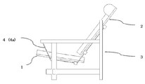
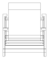
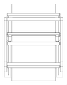
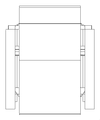
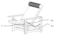
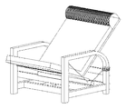
- FIGS. 15 and FIG. 15 show A specific example of one embodiment (embodiment example 1) of the chair of the present invention.
- FIGS. 13 and 14 show the expression of the specific example of the further example (example 5).
- the chair of the present invention is mainly provided with a seat surface (1) for supporting a person's buttocks, a backrest (2) for supporting a person's back, and standing on the ground, and the seat surface and the backrest are predetermined from the ground. And a support leg (3) for supporting at the height position.
- the seat surface (1) and the backrest (2) are not directly fixed to the support leg (3), but the wire member (4) or the auxiliary support member ( 7), it is attached indirectly and rockingly to constitute a chair.
- the seating surface (1) in the present invention is a structure for supporting a person's buttocks, and can take a square or any other shape, but the front end on the side corresponding to the person's knee and the rear end on the rear side. There is a department.
- the seat surface (1) may be configured independently of the backrest (2) or may be connected and fixed. Then, as will be described later, the seat surface of the present invention is suspended by one or more sets of wire members (4) that are fixedly or movably attached to and supported by the support legs in the following mode (i) or (ii). It is characterized by being supported by being lowered.
- One aspect thereof is (i) in which a seating surface is positioned between at least one pair of wire members stretched in parallel or in parallel between the front and rear of the support leg, and the seating surface (1) And, the backrest (2) is characterized in that it is supported by being suspended at a substantially central portion of the wire member.
- the substantially central portion means a portion excluding the end portion. Examples of this embodiment include FIGS. 1 to 13.
- (Ii) which is another aspect of the present invention, is (ii) one or more sets of the wire members (4) suspended from the left and right of the support legs, and the seat surface (1) and / or
- the backrest (2) is characterized by being supported by suspension.
- FIGS. 14 to 16 are examples of this mode.
- the seating surface (1) is connected to the front or back of the one or more sets of wire members independently or along the wire member (4).
- the one or more sets of wire members are supported so as to be slidable in the front-rear direction of the support leg, so that the position of the seating surface is substantially changed.
- the feature is that the depth position can be adjusted by changing the depth.
- Any material used for the seating surface of a conventional chair or sofa can be adopted as the material constituting the seating surface, but from various hard materials such as wood, steel, leather, cloth, woven fabric of bamboo or rattan, etc. There are even soft ones. It is also preferable to take not only a plate shape but also a sawtooth shape.
- the backrest (2) in the present invention is a structure for supporting the back of a person and can take any shape other than a square, but has an upper end (2ab) and a lower end (2cd). Then, it is attached and supported between at least one pair of parallel or parallel wire members, which will be described later, and the backrest is fixedly or movably attached to and supported by the support leg in the mode of (i) or (ii). Further, it is supported by being suspended by one or more sets of wire members (4). Further, preferably, in the aspect of (i), the one or more sets of wire members are supported so as to be slidable back and forth independently along the wire member (4) or connected to the seat surface.
- the position of the backrest can be substantially changed back and forth by supporting the one or more sets of wire members so as to be slidable in the front-rear direction of the support leg. It is.
- the material constituting the backrest can be selected from the same material as the seating surface.
- the shape can also be square or any other shape. For example, a raised shape for supporting a person's shoulder or head may be provided on the upper portion of the backrest (2).
- the support leg (3) is a structure for standing on the ground and indirectly supporting the seating surface and the backrest at a predetermined height position from the ground, and is configured by a combination of columnar bodies. Even if it exists, the structure by a plate-shaped object may be sufficient. For example, in the case of a structure having a combination of columnar bodies as shown in FIG.
- a pair of front legs including a right front leg (3a) and a left front leg (3b), a right rear leg (3c), and a left rear leg (3d)
- a leg member comprising a pair of rear legs, and A fixed front frame member (3e) for fixing the distance between the right front leg (3a) and the left front leg (3b) constant, and the distance between the right rear leg (3c) and the left rear leg (3d) is fixed constant.
- the upper right frame member (3i) which is fixed and functions as an armrest, is fixed, and the upper part of the left front leg (3b) and the upper part of the left rear leg (3d) are fixed at a constant interval to be used as an armrest.
- a fixed upper left frame member (3j) for functioning, and a fixed distance between the right rear leg (3c) and the left rear leg (3d) It is preferably made of a upper frame member comprising a fixed rear upper frame member (3k).
- a support leg is used instead of the combination of the right front leg (3a), the right rear leg (3b), the fixed right frame member (3g), and the fixed upper right frame member (3i).
- You may comprise by a plate-shaped object.
- the entire support leg may be integrally processed in a three-dimensional shape.
- the material constituting the supporting legs can be selected from metal pipes such as wood and steel used for the structure of conventional chairs and sofas, rattan, and any other hard, high-strength and high weather-resistant material.
- the wire member (4) of the present invention means a rope-shaped material having a tensile strength sufficient to support a seating surface, a backrest and a human body, and is a high-quality string material used for so-called mountain climbing.
- (i) which is one of the embodiments of the present invention, when the mounting support position of the seating surface or the backrest is slid back and forth along the wire member, the shape of the wire member changes due to the load.
- the wire member (4) is composed of an elastic body such as a so-called spring or rubber that slightly expands and contracts in the longitudinal direction.
- an elastic body such as a so-called spring or rubber that slightly expands and contracts in the longitudinal direction.
- the part comprised with an elastic body is chosen among wire members (4) and only the wire member which supports a seat surface rear end is made into an elastic body, for example, the elastic force will be felt only on the back side of the seat surface. Subtle adjustment of goodness becomes possible.
- One end or both ends of the wire member (4) of the present invention are fixedly or movably attached to and supported by the support leg (3), and are members for hanging and supporting the seating surface and the backrest. Requires at least one set (two in total on the left and right) and has the following feature (i) or (ii).
- a set of wire members is formed by stretching two wire members on the left and right sides of the support leg in parallel or in parallel, in the form of spanning the front and the rear, and between the front and rear of the support leg. Composed.
- one end of the wire member is attached to the front of the right support leg, the other end of the wire member is attached to the rear of the right support leg, and the approximate center of the wire member that is not the end is slightly hung
- the wire member of the length is used.
- the seat surface and the backrest are suspended and supported at a substantially central portion of the wire member.
- the seat surface and the backrest are positioned between the pair of wire members, and the seat surface and the backrest slide back and forth independently or connected along the wire members.
- the mounting surface is characterized in that the angle of the seating surface and the backrest and the positional relationship with each other can be adjusted.
- the seating surface (1) and / or the backrest (2) is suspended and supported by one or more sets of the wire members (4) suspended from the left and right sides of the support legs.
- one end portion of the wire member is fixedly or movably attached to and supported by the right support leg, and the other end portion of the wire member is fixed to the rear end portion of the seating surface.
- FIG. 7 to FIG. Embodiment 2 as shown in Fig.
- Embodiment 12 when two seats and an auxiliary wire are used to support the seat and back
- Embodiment 3 as shown in Fig. 13 (the seat and back are integrated, The rear end of the seating surface is supported by a wire member)
- Embodiment 4 as shown in FIG. 14 the rear end of the seating surface (1) is the mode of (ii), that is, a wire having one end attached to the support leg. Since there is a case where it is supported by hanging by a member), it will be separately described below.
- the chair according to Embodiment 1 shown in FIGS. 1 to 6 is a view showing a mode in which a seat surface and a backrest are supported by a pair of wire members (4a) and (4b).
- one end of the right wire member (4a) is fixed or locked to a fixed upper right frame member (3i) positioned in front of the support leg (3), and the other end is behind the support leg (3). It is fixed or locked to the right rear leg (3c) located at the position. Fixing or locking may be performed on other support legs.
- the wire member (4a) is a rod-like protrusion provided on the front and rear sides of the seat surface (1) in a bar-like shape in the lateral direction, and below and above the backrest (2).
- the seat surface and the backrest are suspended and supported by passing through the communication holes provided in the protrusions (2e) and (2f), respectively.
- the suspended attachment position can slide back and forth along the wire member, and can be fixed at an arbitrary position.
- a stopper or the like can be used.
- the structure to be fixed includes devising the shape of the communication hole, and using the frictional force between the hole and the wire member to fix and release it.
- various other devised hole shapes such as adopting a U-shape can be adopted.
- the chair of embodiment 2 basically uses two sets of wire members (4a) (4b) and (4c) (4d), one (4a) (4b) supports the seat surface (1), and the other (4c) and (4d) are examples in which the backrest (2) is supported. More preferably, the seat member supporting wire members (4a) and (4b) are supported by suspending and supporting only the rear end portion of the seat surface so that the front end portion of the seat surface is stretched between the front legs of the chair.
- the support member supported by the auxiliary wire (7) and the wire members (4c) and (4d) for supporting the backrest are supported by hanging only the lower end portion of the backrest so as to be slidable, and the upper end portion of the backrest is supported by the chair.
- each of the right support leg and the left support leg has a predetermined height from the ground of the right support leg, for example, on the right side.
- a fixed locking portion (5) for fixing or locking the both end portions of the right side seating surface support wire member (4a) is provided at two locations, the front and the rear.
- the height of the fixed locking portion may be different from front to back.
- the term “locking” refers to locking in a state where fixing and releasing are easy.
- the wire member (4) is a member whose length is slightly longer than the distance between the fixed locking portions, and its substantially central portion hangs downward from the height of the fixed locking portion, Fixed or locked.
- the rear right end (1c) of the seating surface (1) of the present invention is suspended and supported by the substantially central portion of the right seating surface supporting wire member (4a). And since it is suspended and supported at a position where the height of the rear end portion of the seat surface is slightly lower than the height of the front end portion of the seat surface, which will be described later, the seat surface is slightly lower rearward It is so inclined.
- a specific structure for suspending and supporting the rear right end portion (1c) of the seat surface by the right seat surface support wire member (4a) for example, a rod shape that protrudes in the shape of a rod fixed to the rear of the seat surface.
- the suspending position can be slid to any position along the wire member, and the hole (6a) and the wire can be changed by devising the shape of the hole (6a) or by devising how to wire the wire member.
- a frictional force with the member (4a) it can be movably fixed at an arbitrary position. Any other movable fixing method can be adopted.
- the front end portion (1ab) of the seat surface (1) is supported on the auxiliary wire (7) stretched between the left and right front legs in front of the support leg.
- a mode of placing and supporting is mentioned.
- the auxiliary wire member (7) is installed such that the front end (1ab) of the seating surface (1) is located slightly above the rear end (1cd), the seating surface is slightly later. Inclination is preferable because a relaxed feeling can be obtained when sitting.
- the front end (1ab) of the seating surface (1) is in a state of being placed on the auxiliary wire member (7), and the front end and the auxiliary are interlocked with the sliding movement of the rear end (1cd) before and after.
- auxiliary wire Attach it at an angle in the direction of overturning (i.e., attach it so that it is not standing upright on the ground but tilted upward), and attach the end of the auxiliary wire to the lower part of the front leg (specifically, fix between the front legs, It is preferable that the structure be extended and attached to the fixed front frame member (3e)) because the strength and shape stability of the entire chair by the force related to the auxiliary wire (7) can be enhanced. Further, this auxiliary wire can be replaced by an auxiliary support leg attached between the front legs or a rolling bearing attached thereto.
- each of the right support leg and the left support leg for example, on the right side, a predetermined height from the ground of the right support leg (the fixed locking part supporting the seat surface).
- Fixed locking portions (5c, 5d) for fixing or locking the both end portions of the right rear surface supporting wire member (4c) are provided at two positions, front and rear, above the position.
- the right rear support wire member (4c) is a member whose length is slightly longer than the distance between the front fixed locking part (5c) and the rear fixed locking part (5d), and is substantially at the center. The part is below the height of the fixed locking part, but is fixed or locked so as to hang down in a range above the hanging position of the rear end of the seating surface.
- the lower right end (2c) of the backrest (2) of the present invention is suspended and supported at the substantially central portion of the right back support wire member (4c).
- the specific structure for suspending and supporting the lower right end (2c) of the backrest by the right seat surface support wire member (4c) can be the same as the structure of the seat surface described above.
- the hanging position of the backrest can also be moved and fixed at an arbitrary position along the wire member.
- the lower end (2cd) is installed so that the lower end (2cd) is inclined slightly forward rather than the upper end (2ab) of the backrest (2), so that a relaxed feeling can be obtained when sitting. .
- the angle of the backrest changes by moving the position of the lower end of the backrest back and forth without changing the position of the upper end of the backrest, the user can change the angle according to the purpose of use such as reading or napping. Can be adjusted.
- the upper part of the backrest (2) is supported by leaning on an auxiliary wire member (7b) that is fixed and locked at both ends of the support leg constituting the rear leg at two left and right positions of a predetermined height. It is an aspect to do. Similar to the seating surface, this auxiliary wire can be replaced by a supporting leg attached between the rear legs or a rolling bearing attached thereto.
- the support position of the upper end portion is not necessarily the end portion, and any position can be selected as long as it is an upper portion that is half or more of the backrest.
- the position of the lower end (2cd) and the upper position of the backrest (2) can be moved slightly back and forth, the inclination angle and position of the backrest can be finely adjusted.
- the inclination angle of the seating surface (1) and the inclination angle of the backrest (2) can be larger than those in the example of the first embodiment. Since the front and back position fluctuation range of the surface and the backrest is wide, there is an advantage that the depth of the seat surface can be adjusted according to the body shape of the seated person.
- the chair of embodiment 3 is basically an example in which the chair of embodiment 2 is simply configured, and since the seat surface (1) and the backrest (2) are connected and integrated, the angle of the seat surface and the backrest is It is fixed.
- the rear end portion of the seating surface is supported basically using a set of wire members (4a) and (4b).
- the wire member (4a) for supporting the seating surface supports only the rear end portion of the seating surface so as to be slidable, while the front end portion of the seating surface is stretched between the front legs of the chair. It is an aspect supported by the auxiliary support member (7).
- assistant support member a wire-shaped thing may be used, and the member of the material similar to a support leg body, and the rolling support attached to it may be used.
- at least a part of the wire member (4) and the auxiliary support member (7) is provided with an elastic body such as a rubber or a spring which has strength and weather resistance and is bent or shakes slightly when a load is applied. It is also possible to configure.
- FIG. 13 shows an example in which a part (4e) of the rear portion of the wire member (4) is made of an elastic body, and the seat surface rear slightly sinks when seated, thereby obtaining a more sense of fluctuation. Can relax.
- an elastic structure for receiving the wire member with some elasticity when a load is applied to the wire member, even when the wire member is attached to the support leg May be installed.
- a mode in which a spring is wound around the lower part of the leg and a ring-shaped attachment part of the wire member is provided on the upper part of the spring can be adopted.
- Embodiment 4 shown in FIG. 14 is a chair corresponding to the embodiment (ii) of the present invention, unlike Embodiments 1 to 3 described above.
- the example which connected and integrated the seat surface and the backrest is shown in this figure, you may comprise and support each independently.
- one end of the wire member (4) is attached to the left and right support legs, specifically to the substantially central portion of the fixed frame member, so as to be slidable back and forth.
- the other end suspends and supports the rear end of the seating surface (1).
- both end portions may be attached to the fixed frame member, and the rear end portion of the seating surface may be suspended and supported at a substantially central portion.
- the front end portion of the seat surface is supported by an auxiliary support member (7) stretched between the front legs of the chair.
- an auxiliary support member (7) stretched between the front legs of the chair.
- the aspect of the fourth embodiment is suspended by one wire member as compared with the aspects of the first to third embodiments, it is difficult to feel the fluctuation. Therefore, you may comprise a wire member with an elastic body. On the other hand, in this aspect, since the wire member itself does not need to be variable, it may be made of a material that emphasizes strength and the like.
- Embodiment 5 shown in FIG. 15 and FIG. 16 is a chair of an aspect corresponding to a further development of Embodiment 3 and Embodiment 4.
- FIG. 15 shows a mode in which the inclination of the seat and the backrest when used for reading or watching TV is reduced (referred to as “upright mode” for convenience), and FIG. 16 increases the inclination when used for napping.
- This mode (referred to as “tilt mode” for convenience) can not only adjust the tilt angle of the subtle seating surface (backrest) within the vertical mode and tilt mode, but also between the vertical mode and the tilt mode. It has the merit that the inclination angle of the seating surface (backrest) can be changed with a simple operation.
- the front end portion (1ab) of the seating surface is supported by being placed on the auxiliary support member (7) positioned in front of the support leg as in the second to fourth embodiments. 15 and the like, the left and right front end portions of the seating surface may be suspended and supported by wire members having one end fixed or locked to the support leg. And the rear-end part (1cd) of the seat surface is suspended and supported by the wire member (4).
- One end (4f) of the wire member (4) that supports the suspension of the rear end of the seating surface is fixedly or movably attached to the front of the support leg, and the other end (4g) is A support leg is movably attached.
- the wire member (4g) on the other end side is mounted and supported so as to be slidable along the supporting leg, and the movable mounting portion is positioned on the fixed upper right frame member (3i), and the fixed upper right frame member ( 3i) in the upright mode (FIG. 15) that can slide horizontally and back and forth, slide and move up and down along the right rear leg (3c), and move the fixed upper right frame member (3i)
- the movable mounting portion is positioned on the fixed upper right frame member (3i), and the fixed upper right frame member ( 3i) in the upright mode (FIG. 15) that can slide horizontally and back and forth, slide and move up and down along the right rear leg (3c), and move the fixed upper right frame member (3i)
- FIG. 16 an inclination mode in which the inclination of the seating surface and the backrest is further increased.
- an elastic structure (8) is installed in the attachment portion of the wire member to the right rear leg (3c) to receive the wire member with some elasticity when a load is applied.
- the configuration is optional, and such a configuration is preferable because the feeling of fluctuation is further increased.
- the right rear leg (3c) constituting the support leg and the fixed upper right frame member (3i) for fixing between the right front leg and the right rear leg are connected to form a sliding movement of the movable attachment portion. It is preferable to adopt a configuration that allows smooth operation.
- This connecting structure may be square or an arched connecting structure as shown in FIGS. 15 and 16 is preferable.
- the wire member (4) constituting the embodiment 5 may be a deformable material such as a string-like rope or a stainless steel chain, or a material that is not variable, such as a stainless steel bar or wood. It may be.
- the wire member may be formed by one, or may be formed by two wires: a wire member located in front of the attachment site with the rear end of the seat surface and a wire member located behind.
- the attachment portion at the rear end portion of the seating surface may be slid along the wire member in the tilt mode.
- the slight inclination can be adjusted as in the fourth embodiment of FIG.
- the length of the auxiliary wire (7) that supports the front end of the seat surface in a suspended manner is adjusted instead of or together with the rear end of the seat surface being moved back and forth.
- the angle of the seating surface can be adjusted by changing the vertical position of the front end portion of the seating surface.
- the chair of the further aspect which can be made can be made.
- the position of the upper end of the backrest can be changed back and forth by changing the position of the auxiliary wire or auxiliary support member in the front-rear direction. You can also adjust the angle.
- the chair of the present invention has at least one set of wire members (4) in which the seating surface and / or the back surface is fixedly or movably attached to and supported by the support legs in the mode (i) or (ii). ), It is characterized by being supported by hanging, and it is possible to experience the comfort of sitting by bouncing or the like when sitting.
- the chair of the present invention can be slid to an arbitrary fixed position along one or more sets of wire members stretched in parallel or in parallel with the front and rear of the support leg, so that the inclination angle of the seat surface (1) can be adjusted,
- the seat surface (1) can be easily adjusted in the front-rear position, and the reclining shape of the chair can be finely adjusted according to the size and preference of the seated person, and subtle fluctuations can be experienced. it can.
- the features of the present invention have been described above in the case of a chair for one person, but the chair of the present invention can also be used as a chaise longue (bench) for two or three persons.
- the sofa of this invention is a sofa which has the basic structure in said chair, Comprising: It is comprised by the sofa which comprised what was called a cushioning material on the basic structure.
- the cushion material so-called cushions and cushions using various materials such as cotton, polyester, and urethane materials can be placed and used on the seat surface and the backrest.
Landscapes
- Chairs For Special Purposes, Such As Reclining Chairs (AREA)
- Chairs Characterized By Structure (AREA)
Priority Applications (1)
| Application Number | Priority Date | Filing Date | Title |
|---|---|---|---|
| JP2014502406A JP6143013B2 (ja) | 2012-03-02 | 2013-02-28 | 椅子又はソファ |
Applications Claiming Priority (6)
| Application Number | Priority Date | Filing Date | Title |
|---|---|---|---|
| JP2012-064409 | 2012-03-02 | ||
| JP2012064409 | 2012-03-02 | ||
| JP2012-128395 | 2012-05-19 | ||
| JP2012128395 | 2012-05-19 | ||
| JP2012-138210 | 2012-06-02 | ||
| JP2012138210 | 2012-06-02 |
Publications (2)
| Publication Number | Publication Date |
|---|---|
| WO2013129637A2 true WO2013129637A2 (fr) | 2013-09-06 |
| WO2013129637A3 WO2013129637A3 (fr) | 2013-11-07 |
Family
ID=49083406
Family Applications (1)
| Application Number | Title | Priority Date | Filing Date |
|---|---|---|---|
| PCT/JP2013/055599 Ceased WO2013129637A2 (fr) | 2012-03-02 | 2013-02-28 | Chaise ou fauteuil |
Country Status (2)
| Country | Link |
|---|---|
| JP (1) | JP6143013B2 (fr) |
| WO (1) | WO2013129637A2 (fr) |
Cited By (1)
| Publication number | Priority date | Publication date | Assignee | Title |
|---|---|---|---|---|
| CN115088979A (zh) * | 2022-05-21 | 2022-09-23 | 嘉善沣德家具有限公司 | 一种多连杆角度调节沙发床 |
Family Cites Families (2)
| Publication number | Priority date | Publication date | Assignee | Title |
|---|---|---|---|---|
| JPS6253613A (ja) * | 1985-09-02 | 1987-03-09 | 横田 一男 | 前後左右揺動椅子 |
| JPH0527879Y2 (fr) * | 1987-10-31 | 1993-07-16 |
-
2013
- 2013-02-28 WO PCT/JP2013/055599 patent/WO2013129637A2/fr not_active Ceased
- 2013-02-28 JP JP2014502406A patent/JP6143013B2/ja not_active Expired - Fee Related
Cited By (2)
| Publication number | Priority date | Publication date | Assignee | Title |
|---|---|---|---|---|
| CN115088979A (zh) * | 2022-05-21 | 2022-09-23 | 嘉善沣德家具有限公司 | 一种多连杆角度调节沙发床 |
| CN115088979B (zh) * | 2022-05-21 | 2023-04-28 | 嘉善沣德家具有限公司 | 一种多连杆角度调节沙发床 |
Also Published As
| Publication number | Publication date |
|---|---|
| JPWO2013129637A1 (ja) | 2015-07-30 |
| WO2013129637A3 (fr) | 2013-11-07 |
| JP6143013B2 (ja) | 2017-06-07 |
Similar Documents
| Publication | Publication Date | Title |
|---|---|---|
| CA2801320C (fr) | Chaise pliable pourvue d'un support dorsal pliable | |
| KR101658486B1 (ko) | 스트레칭 기능을 가진 의자 | |
| TWD110925S1 (zh) | 椅子 | |
| JP2018523510A (ja) | 家具部材用リクライニング/レッグレスト機構 | |
| US8997274B2 (en) | Adjustable furniture apparatus | |
| DK2981194T3 (en) | SHARE WITH ADJUSTABLE CONFIGURATION FOR REALIZING ARM LINES OR SEAT LINES. | |
| CN106108444B (zh) | 一种用于可躺椅的框架结构 | |
| KR20200110966A (ko) | 의자의 요추지지부 구조 | |
| US20200329877A1 (en) | Beach bed | |
| JP6143013B2 (ja) | 椅子又はソファ | |
| KR100886181B1 (ko) | 장애인용 의자 | |
| KR101399443B1 (ko) | 등받이 각도 조절장치가 설치된 조립식 쇼파 | |
| KR101485176B1 (ko) | 높이 조절 가능한 의자 | |
| CN222217536U (zh) | 一种椅子 | |
| JP2019097754A (ja) | 椅子 | |
| KR101187011B1 (ko) | 다기능 낚시의자 | |
| KR200492509Y1 (ko) | 그물망 벤치 | |
| KR200473715Y1 (ko) | 등받이 방석 | |
| CN215874039U (zh) | 一种座椅 | |
| KR102952269B1 (ko) | 다리받침대를 가지는 낚시의자 | |
| CN220713416U (zh) | 一种可调节躺椅 | |
| CN218419043U (zh) | 一种多功能折叠躺椅 | |
| RU155076U1 (ru) | Кресло | |
| CN202077904U (zh) | 一种编藤摇椅 | |
| CN210493365U (zh) | 一种简洁折叠椅 |
Legal Events
| Date | Code | Title | Description |
|---|---|---|---|
| 121 | Ep: the epo has been informed by wipo that ep was designated in this application |
Ref document number: 13754931 Country of ref document: EP Kind code of ref document: A2 |
|
| ENP | Entry into the national phase |
Ref document number: 2014502406 Country of ref document: JP Kind code of ref document: A |
|
| 122 | Ep: pct application non-entry in european phase |
Ref document number: 13754931 Country of ref document: EP Kind code of ref document: A2 |