WO2013129736A1 - 휴대용 단말기의 충전장치 및 방법 - Google Patents
휴대용 단말기의 충전장치 및 방법 Download PDFInfo
- Publication number
- WO2013129736A1 WO2013129736A1 PCT/KR2012/003779 KR2012003779W WO2013129736A1 WO 2013129736 A1 WO2013129736 A1 WO 2013129736A1 KR 2012003779 W KR2012003779 W KR 2012003779W WO 2013129736 A1 WO2013129736 A1 WO 2013129736A1
- Authority
- WO
- WIPO (PCT)
- Prior art keywords
- terminal
- portable terminal
- charging
- terminals
- usb
- Prior art date
- Legal status (The legal status is an assumption and is not a legal conclusion. Google has not performed a legal analysis and makes no representation as to the accuracy of the status listed.)
- Ceased
Links
Images


Classifications
-
- H—ELECTRICITY
- H04—ELECTRIC COMMUNICATION TECHNIQUE
- H04B—TRANSMISSION
- H04B1/00—Details of transmission systems, not covered by a single one of groups H04B3/00 - H04B13/00; Details of transmission systems not characterised by the medium used for transmission
- H04B1/38—Transceivers, i.e. devices in which transmitter and receiver form a structural unit and in which at least one part is used for functions of transmitting and receiving
- H04B1/40—Circuits
-
- H—ELECTRICITY
- H02—GENERATION; CONVERSION OR DISTRIBUTION OF ELECTRIC POWER
- H02J—ELECTRIC POWER NETWORKS; CIRCUIT ARRANGEMENTS OR SYSTEMS FOR SUPPLYING OR DISTRIBUTING ELECTRIC POWER; SYSTEMS FOR STORING ELECTRIC ENERGY
- H02J7/00—Circuit arrangements for charging or discharging batteries or for supplying loads from batteries
- H02J7/40—Circuit arrangements for charging or discharging batteries or for supplying loads from batteries characterised by the exchange of charge or discharge related data
- H02J7/44—Circuit arrangements for charging or discharging batteries or for supplying loads from batteries characterised by the exchange of charge or discharge related data between battery management systems and power sources
-
- H—ELECTRICITY
- H02—GENERATION; CONVERSION OR DISTRIBUTION OF ELECTRIC POWER
- H02J—ELECTRIC POWER NETWORKS; CIRCUIT ARRANGEMENTS OR SYSTEMS FOR SUPPLYING OR DISTRIBUTING ELECTRIC POWER; SYSTEMS FOR STORING ELECTRIC ENERGY
- H02J7/00—Circuit arrangements for charging or discharging batteries or for supplying loads from batteries
-
- H—ELECTRICITY
- H02—GENERATION; CONVERSION OR DISTRIBUTION OF ELECTRIC POWER
- H02J—ELECTRIC POWER NETWORKS; CIRCUIT ARRANGEMENTS OR SYSTEMS FOR SUPPLYING OR DISTRIBUTING ELECTRIC POWER; SYSTEMS FOR STORING ELECTRIC ENERGY
- H02J7/00—Circuit arrangements for charging or discharging batteries or for supplying loads from batteries
- H02J7/485—Circuit arrangements for charging or discharging batteries or for supplying loads from batteries with provisions for charging different types of batteries
-
- H—ELECTRICITY
- H02—GENERATION; CONVERSION OR DISTRIBUTION OF ELECTRIC POWER
- H02J—ELECTRIC POWER NETWORKS; CIRCUIT ARRANGEMENTS OR SYSTEMS FOR SUPPLYING OR DISTRIBUTING ELECTRIC POWER; SYSTEMS FOR STORING ELECTRIC ENERGY
- H02J7/00—Circuit arrangements for charging or discharging batteries or for supplying loads from batteries
- H02J7/40—Circuit arrangements for charging or discharging batteries or for supplying loads from batteries characterised by the exchange of charge or discharge related data
- H02J7/42—Circuit arrangements for charging or discharging batteries or for supplying loads from batteries characterised by the exchange of charge or discharge related data with electronic devices having internal batteries, e.g. mobile phones
Definitions
- the present invention relates to a charging device and a method of a portable terminal, and to a charging device and a method of a portable terminal capable of rapidly charging a variety of portable terminals (ie, mobile phones) by determining the portable terminal device connected to the USB port. It is about.
- Batteries are essential for the use of existing portable terminals. To this end, charging was generally performed by connecting a portable terminal to a power terminal. However, there is a disadvantage that it is difficult to charge it when moving, such as driving a vehicle.
- the portable terminal is being charged by plugging it into a USB terminal instead of a power terminal.
- smartphone chargers such as iPhones or Galaxys use dedicated chargers for each of them, but in the case of common chargers, the USB port is composed of multiple terminals.
- the current connected portable device does not recognize whether the iPhone or Galaxy phone is configured separately for the iPhone terminal and the terminal for the Galaxy phone, there is a disadvantage that must be connected to each model even when charging.
- An object of the present invention is to determine the type of mobile phone connected to the USB terminal, through which a single USB terminal can provide a charging device and method of a portable terminal capable of rapidly charging various types of mobile phones.
- a charging device for charging a portable terminal comprising: a power supply unit for supplying power for charging, a USB terminal connected to an external portable terminal, and a USB for varying its charging voltage according to a portable terminal connected to a USB terminal
- a charging device for a portable terminal comprising a central processor configured to control the operation of the USB line controller by determining a portable terminal connected to the line controller and the USB terminal.
- a first resistor R1 connected between the USB line controller, a power supply voltage VCC and a first terminal D +, a second resistor R2 connected between the first terminal D + and a ground;
- the third resistor R3 connected to the first terminal D + and the monitoring terminal Vs, the fourth resistor R4 connected between the second terminal D- and the first switch SW1, and the power supply voltage.
- the fifth resistor R5 connected to the VCC and the second terminal D-, the first switch SW1 connected between the fourth resistor R4 and the ground terminal, and the second terminal D-.
- a sixth resistor R6 connected between the ground terminal and the ground terminal, and a second switch SW2 connected between the first terminal D + and the second terminal D ⁇ .
- the first and second switches may use any one of a transistor, an FET, and a switching IC operating according to a signal of the central processing unit.
- the central processing unit may determine the connected portable terminal by using the voltage value of the monitoring terminal.
- the charging method for a portable terminal connected to a USB terminal having a first and a second terminal comprising the steps of: monitoring the voltage values of the first and second terminals to determine the type of the portable terminal; When the first portable terminal is connected according to the determination, the voltage of the first and second terminals is changed to a condition for rapid charging of the first portable terminal, and if the second portable terminal is connected, And changing the voltages of the first and second terminals to conditions for rapid charging of the second portable terminal, and determining that the terminal is out of the terminal if the portable terminal is not connected as a result of the determination. It provides a charging method of the terminal.
- the first and second portable terminals may perform rapid charging after determining whether the first and second terminals may be rapidly charged by determining the voltages of the first and second terminals.
- the step of determining the type of the terminal and changing the conditions for rapid charging may include setting a voltage value of the monitoring terminal using the voltage values of the first and second terminals, and using the voltage value of the monitoring terminal.
- a first step of determining whether or not the portable terminal is connected and if the first portable terminal is connected as a result of the first determination, the first portable terminal is charged, and if the first portable terminal is not connected, the first portable terminal is charged.
- Changing the voltage value of the monitoring terminal by changing the voltage value of the first and second terminals; and secondly determining whether or not the second portable terminal is connected by checking the changed voltage value of the monitoring terminal again. As a result, when the second portable terminal is connected, the second portable terminal is charged. If the second portable terminal is not connected, the terminal is charged. It characterized in that the phthaloyl determined.
- the change in the voltage value of the first and second terminals is characterized by conducting the first and second terminals and connecting an additional resistor.
- the method may further include determining whether a bad terminal is connected according to the voltages of the first and second terminals, and disconnecting the USB power as a result of the bad determination.
- the determination of whether or not the bad terminal is connected may determine whether it is in a short state or 0V, and the terminal departure determination may be performed to determine a no-load state.
- the present invention enables the identification of various types of portable terminals, that is, mobile devices, through a single USB terminal, and provides a rapid charging voltage for the portable terminal, so that the portable terminal can proceed with rapid charging.
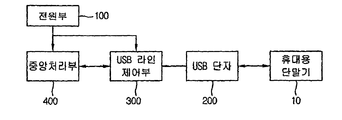
- FIG. 1 is a block diagram of a charging device of a portable terminal according to an embodiment of the present invention.
- FIG. 2 is a circuit diagram of a USB line controller according to an embodiment.
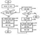
- FIG. 3 is a flowchart illustrating a charging method of a portable terminal according to an embodiment of the present invention.
- FIG. 4 is a flowchart illustrating a charging method of a portable terminal according to a variation of an embodiment.
- 1 is a block diagram of a charging device of a portable terminal according to an embodiment of the present invention.
- 2 is a circuit diagram of a USB line controller according to an embodiment.
- the apparatus for fast charging a portable terminal includes a power supply unit 100 for supplying power for charging, a USB terminal 200 connected to an external portable terminal 10, and According to the portable terminal 10 connected to the USB terminal 200, the USB line controller 300 for varying its charging voltage and the portable terminal 10 connected to the USB terminal 200 are determined to determine the USB line controller ( A central processing unit 400 for controlling the operation of 300 is provided.
- the portable terminal 10 when the portable terminal 10 is connected to the USB terminal 200, the voltages of the first and second terminals D + and D- are checked through a monitoring terminal, and the portable terminal 10 Determine the type. Thereafter, the internal switch is adjusted to set the fast charging condition for the portable terminal 10. Through this, the rapid charging of the portable terminal 10 can be performed.
- the power supply unit 100 may use various power supply devices to which the USB terminal 10 is connected.
- the power supply unit 100 of the present embodiment preferably generates a power supply voltage VCC.
- the present invention is not limited thereto, and the power supply unit 100 may generate power in various forms.
- the USB terminal 200 includes a first terminal D + and a second terminal D ⁇ connected to an external terminal.
- the USB line controller 300 is connected between the central processing unit 400 and the USB terminal 200 to provide the power supply voltage VCC of the power supply unit 100 to the USB terminal 200.
- the USB line controller 300 varies the voltage provided from the power supply unit 100 to the USB terminal 200 by using a plurality of resistors and switches.
- the USB line controller 300 may include a first resistor R1 connected between the power supply voltage VCC and the first terminal D +, and between the first terminal D + and ground. Connected between the connected second resistor R2, the first terminal D + and the third resistor R3 connected to the monitoring terminal Vs, and between the second terminal D- and the first switch SW1. First resistor R4 connected to the fourth resistor R4, the power supply voltage VCC and the second terminal D ⁇ , and a first switch connected between the fourth resistor R4 and the ground terminal. SW1, the sixth resistor R6 connected between the second terminal D- and the ground terminal, and the second switch SW2 connected between the first terminal D + and the second terminal D-. It includes.
- transistors that operate the first and second switches SW1 and SW2 according to the control signal of the central processing unit 400.
- the present invention is not limited thereto, and it is possible to use a switch that is turned on or off according to an external signal.
- transistors, FETs, switching ICs, and the like can be used.
- Ra is a parallel resistance value of the first resistor R1 and the fifth resistor R5, and Rb is a parallel resistance value of the second resistor R2, the fourth resistor R4, and the sixth resistor R6. .
- the central processing unit 400 determines the portable terminal 10 to be connected. To this end, the voltage change of the monitoring terminal Vs of the USB line controller 300 is sensed. For example, when the initial voltage is maintained without a voltage change of the monitoring terminal Vs, the first terminal is recognized as the first portable terminal, and when there is a voltage change, the second terminal is recognized as the second portable terminal.
- a recognition method is not limited to the above description and may vary.
- the central processing unit 400 controls the operation of the first and second switches SW1 and SW2 to vary the voltages of the first and second terminals D + and D ⁇ to set a fast charging condition for the second portable terminal. Set it.
- the portable terminal checks the voltages of the connected first and second terminals D + and D-, checks whether or not the fast charging is possible, and then proceeds with rapid charging.
- the central processing unit 400 and the USB line control unit 300 have been described as being separated, but the present invention is not limited thereto, and they may be manufactured in a single chip form.
- a separate switch and a resistor may be added to change the voltage values provided through the first and second terminals D + and D ⁇ , thereby charging the portable terminal having various fast charging voltage values.
- FIG. 3 is a flowchart illustrating a rapid charging method of a portable terminal according to an embodiment of the present invention.
- a mobile device which is a portable terminal, is connected to a USB terminal of a charging device of a portable terminal (S110).
- USB connection line is a line which can be connected to the first and second portable terminals whose charging voltages are different.
- the voltages of the first and second terminals D + and D ⁇ are set to voltages for rapid charging of the first portable terminal.
- the first and second switches SW1 and SW2 in the USB line control unit are turned off (ie, short circuited). Of course, this may be the voltage for rapid charging, but may also maintain the initial voltage.
- the initial voltage value is set to the monitoring terminal Vs, and the monitoring voltage when the first portable terminal is connected is correct, and if it is correct, the first portable terminal is recognized.
- the USB line controller 300 may provide the central processing unit 400 with the voltage of the first terminal D + as the monitoring terminal Vs by internal voltage distribution.
- the central processing unit 400 may determine whether the first portable terminal is connected by determining the voltage of the monitoring terminal VS.
- the determination may be based on comparing the voltage of the monitoring terminal Vs with a preset reference voltage.
- the present invention is not limited thereto, and the determination method may be various. That is, it may be based on the case where there is no change in the voltage of the monitoring terminal Vs, that is, the first terminal and when the change occurs.
- the first portable terminal is charged (S130). At this time, the first portable terminal determines that the setting of the first terminal D + and the second terminal D ⁇ of the charging device is in a state in which charging is possible (S131). After such confirmation, the first portable terminal is charged (S132).
- the voltages of the first and second terminals D + and D ⁇ may be adjusted to set conditions for rapid charging of the first portable terminal. That is, the voltage level of the first terminal (D +) and the second terminal (D ⁇ ) and the first terminal (D +) and the second terminal (D-) are the same as those of the dedicated charging device for the first portable terminal. If so, the terminal side recognizes it and proceeds with rapid charging.
- the voltages of the first and second terminals D + and D ⁇ are set to voltages for rapid charging of the second portable terminal.
- the first and second switches SW1 and SW2 in the USB line controller are turned on.
- voltages of the first and second terminals D + and D ⁇ may be changed by changing resistance values in the USB line controller.
- the voltage value of the monitoring terminal Vs is again checked to determine whether the mobile device is separated (S150).
- the predetermined time is effectively a time after the initial unstable voltage state is stabilized when the portable terminal is connected.
- it is effective to be in the range of 0.1 to 3 seconds.
- the charging is terminated without charging the mobile device. That is, when a voltage is detected in the no-load state in which the USB terminal is opened while the first and second switches SW1 and SW2 are turned on, the portable terminal is recognized as detached. Thereafter, after a predetermined time, the voltages of the first and second terminals D + and D ⁇ may be set back to voltages for rapid charging of the first portable terminal.
- the first and second switches SW1 and SW2 in the USB line controller are turned off (ie, shorted). Of course, this may be the voltage for rapid charging, but may also maintain the initial voltage.
- the connected device recognizes the second portable terminal (S160) and charges the second portable terminal (S170).
- the second portable terminal checks that the settings of the first terminal D + and the second terminal D ⁇ of the charging device are in a state capable of charging (S171). After such confirmation, the second mobile terminal is charged (S172).
- the portable terminal connected to the first terminal D + and the second terminal D- is determined through the voltage change of the monitoring terminal, and the fast charging condition for the determined portable terminal is set. Rapid charging of the portable terminal can be performed.
- the portable terminal may proceed with rapid charging after determining whether the voltage provided by the connected charging device is a voltage for rapid charging, and may perform an effective and safe charging through its internal circuit.
- this invention is not limited to this, Various charging methods can be used.
- FIG. 4 is a flowchart illustrating a charging method of a portable terminal according to a modified example of the embodiment.
- the voltage value of the monitoring terminal Vs is checked, and it is determined whether the voltage value corresponds to the voltage value when the first portable terminal is connected.
- the monitoring terminal (Vs) voltage is determined to determine whether the first portable terminal is connected (S220).
- the type of the portable terminal is determined by monitoring the voltages of the first and second terminals D + and D ⁇ . Then, the first terminal D + and the second terminal D ⁇ of the charging device are adjusted to the conditions for rapidly charging the portable terminal. For example, set the same voltage condition as the fast charger. In addition, the portable terminal may proceed with rapid charging after confirming whether rapid charging is possible through such a change.
- the voltages of the first and second terminals D + and D ⁇ are changed (S240). That is, the first and second switches SW1 and SW2 in the USB line controller are turned on. As a result, voltages of the first and second terminals D + and D ⁇ may be changed by changing resistance values in the USB line controller.
- the voltage value of the monitoring terminal Vs is again checked to determine whether the second portable terminal is connected (S250).
- the determination of whether the terminal is connected includes determining whether the defective portable terminal is connected, and determining whether the portable terminal is separated. The determination may be performed simultaneously or sequentially.
- the determination checks whether the short state or 0V, and if the short state determines that the battery is bad, the power is cut off.
- the charging for the second portable terminal is performed as described above (S260). However, if it is determined that the departure is returned to the initial condition.
Landscapes
- Engineering & Computer Science (AREA)
- Power Engineering (AREA)
- Computer Networks & Wireless Communication (AREA)
- Signal Processing (AREA)
- Charge And Discharge Circuits For Batteries Or The Like (AREA)
Abstract
본 발명은 휴대용 단말기의 급속 충전 장치 및 방법에 관한 것으로, 충전을 위한 전원을 제공하는 전원부; 외부 휴대용 단말기에 접속되는 USB 단자; USB 단자에 접속되는 휴대용 단말기에 따라 이의 충전 전압을 가변시키는 USB 라인 제어부; 및 USB 단자에 접속되는 휴대용 단말기를 판별하여 USB 라인 제어부의 동작을 제어하는 중앙 처리부를 포함하는 것을 특징으로 하는 휴대용 단말기의 급속 충전 장치를 제공한다.
Description
본 발명은 휴대용 단말기의 충전 장치 및 방법에 관한 것으로, USB 포트에 접속된 휴대용 단말기기의 판별을 통해 다양한 휴대용 단말기(즉, 휴대폰)에 대한 급속 충전을 할 수 있는 휴대용 단말기의 충전 장치 및 방법에 관한 것이다.
기존의 휴대용 단말기의 사용을 위해서는 배터리가 필수적이다. 이를 위해 일반적으로는 전원단자에 휴대용 단말기를 연결하여 충전을 진행하였다. 하지만, 차량을 운전하는 것과 같이 이동중일 때는 이를 충전하기 어려운 단점이 있다.
이러한 단점을 보안하기 위해 최근에는 전원단자가 아닌 USB 단자에 꼽아 휴대용 단말기를 충전하고 있다.
그러나, 아이폰 또는 갤럭시폰과 같은 스마트폰용 충전기는 이들 각각에 맞는 전용충전기를 사용하지만, 공용 충전기의 경우 USB 포트가 멀티 단자로 구성되어 있다. 즉, 현재 접속된 휴대용 장치가 아이폰인지 갤럭시폰인지 인식을 하지 못하여 아이폰 단자와 갤럭시폰용 단자가 각기 별도로 구성되어 있으며, 충전시에도 각기 기종에 맞추어 연결하여야 하는 단점이 있다.
본 발명의 목적은 USB 단자에 접속되는 핸드폰의 종류를 파악할 수 있고, 이를 통해 하나의 USB 단자로 여러 종류의 핸드폰을 급속 충전할 수 있는 휴대용 단말기의 충전 장치 및 방법을 제공한다.
본 발명은 휴대용 단말기를 충전하기 위한 충전 장치에 있어서, 충전을 위한 전원을 제공하는 전원부와, 외부 휴대용 단말기에 접속되는 USB 단자와, USB 단자에 접속되는 휴대용 단말기에 따라 이의 충전 전압을 가변시키는 USB 라인 제어부 및 USB 단자에 접속되는 휴대용 단말기를 판별하여 USB 라인 제어부의 동작을 제어하는 중앙 처리부를 포함하는 것을 특징으로 하는 휴대용 단말기의 충전 장치를 제공한다.
상기 USB 라인 제어부, 전원 전압(VCC)과 제 1 단자(D+) 사이에 접속된 제 1 저항(R1)과, 제 1 단자(D+)와 접지 사이에 접속된 제 2 저항(R2)과, 제 1 단자(D+)와 모니터링 단자(Vs)에 접속된 제 3 저항(R3)과, 제 2 단자(D-)와 제 1 스위치(SW1) 사이에 접속된 제 4 저항(R4)과, 전원 전압(VCC)과 제 2 단자(D-)에 접속된 제 5 저항(R5)과, 제 4 저항(R4)과 접지 단자 사이에 접속된 제 1 스위치(SW1)와, 제 2 단자(D-)와 접지 단자 사이에 접속된 제 6 저항(R6)과, 제 1 단자(D+)와 제 2 단자(D-) 사이에 접속된 제 2 스위치(SW2)를 포함하는 것을 특징으로 한다.
상기 제 1 및 제 2 스위치로 상기 중앙 처리부의 신호에 따라 동작하는 트랜지스터, FET 및 스위칭 IC 중 어느 하나를 사용하는 것을 특징으로 한다.
상기 중앙 처리부는 상기 모니터링 단자의 전압값을 이용하여 접속된 휴대용 단말기를 판별하는 것을 특징으로 한다.
또한, 본 발명에 따른 제 1 및 제 2 단자를 갖는 USB 단자에 접속된 휴대용 단말기에 대한 충전 방법에 있어서, 상기 제 1 및 제 2 단자의 전압 값을 모니터링 하여 휴대용 단말기의 종류를 판별하는 단계와, 상기 판별에 따라 제 1 휴대용 단말기가 접속하는 경우, 상기 제 1 및 제 2 단자의 전압을 상기 제 1 휴대용 단말기의 급속 충전을 위한 조건으로 변화시키고, 만일 제 2 휴대용 단말기가 접속하는 경우, 상기 제 1 및 제 2 단자의 전압을 제 2 휴대용 단말기의 급속 충전을 위한 조건으로 변화시키는 단계와, 상기 판별 결과 휴대용 단말기의 접속이 아닌 경우에는 단말기 이탈로 판단하는 단계를 포함하는 것을 특징으로 하는 휴대용 단말기의 충전 방법을 제공한다.
상기 제 1 및 제 2 휴대용 단말기는 상기 제 1 및 제 2 단자의 전압을 판단하여 급속 충전 가능 여부를 확인한 이후 급속 충전을 진행하는 것을 특징으로 한다.
상기 단말기의 종류의 판별과 급속 충전을 위한 조건을 변화사는 단계는, 상기 제 1 및 제 2 단자의 전압 값을 이용하여 모니터링 단자의 전압값을 설정하고, 상기 모니터링 단자의 전압값을 이용하여 제 1 휴대용 단말기의 접속 여부를 1차 판단하는 단계와, 1차 판단결과 제 1 휴대용 단말기가 접속된 경우에는 제 1 휴대용 단말기에 대한 충전을 진행하고, 제 1 휴대용 단말기의 접속이 아닌 경우에는 상기 제 1 및 제 2 단자의 전압 값을 변화시켜 모니터링 단자의 전압값을 변화시키는 단계와, 상기 변화된 모니터링 단자의 전압값을 다시 확인하여 제 2 휴대용 단말기의 접속 여부를 2차 판단하는 단계 및 2차 판단 결과 제 2 휴대용 단말기가 접속된 경우에는 제 2 휴대용 단말기에 대한 충전을 진행하고, 제 2 휴대용 단말기의 접속이 아닌 경우에는 단말기 이탈로 판단하는 것을 특징으로 한다.
상기 제 1 및 제 2 단자의 전압 값의 변화는 제 1 및 제 2 단자를 도통시키고, 추가 저항을 접속시키는 것을 특징으로 한다.
상기 단말기 이탈 판단 단계 전에, 상기 제 1 및 제 2 단자의 전압에 따라 불량 단말기 접속 여부를 판단하는 단계와, 상기 불량 판단 결과 USB 전원을 차단하는 단계를 더 포함하는 것을 특징으로 한다.
상기 불량 단말기 접속 여부의 판단은 쇼트 상태인지 또는 0V인지를 확인하고, 상기 단말기 이탈 판단은 무부하 상태를 판단하는 것을 특징으로 한다.
이와 같이 하여 본 발명은 단일의 USB 단자를 통해 다양한 종류의 휴대용 단말기 즉, 모바일 기기에 대한 판별이 가능하고, 이에 대한 급속 충전 전압을 제공하여 휴대용 단말기가 이를 확인후 급속 충전을 진행할 수 있다.
도 1은 본 발명의 일 실시예에 따른 휴대용 단말기의 충전 장치의 블록도.
도 2는 일 실시예에 따른 USB 라인 제어부의 회로도.
도 3은 본 발명의 실시예에 다른 휴대용 단말기의 충전 방법을 설명하기 위한 흐름도.
도 4는 일 실시예의 변혀예에 다른 휴대용 단말기의 충전 방법을 설명하기 위한 흐름도.
이하, 첨부된 도면을 참조하여 본 발명의 실시예를 더욱 상세히 설명하기로 한다. 그러나 본 발명은 이하에서 개시되는 실시예에 한정되는 것이 아니라 서로 다른 다양한 형태로 구현될 것이며, 단지 본 실시예들은 본 발명의 개시가 완전하도록 하며, 통상의 지식을 가진 자에게 발명의 범주를 완전하게 알려주기 위해 제공되는 것이다. 도면상에서 동일 부호는 동일한 요소를 지칭한다.
본 명세서에서의 구성부들에 대한 구분은 각 구성부가 담당하는 주기능별로 구분한 것에 불과함을 명확히 하고자 한다. 즉, 이하에서 설명할 2개 이상의 구성부가 하나의 구성부로 합쳐지거나 또는 하나의 구성부가 보다 세분화된 기능별로 2개 이상으로 분화되어 구비될 수도 있다. 그리고 이하에서 설명할 구성부 각각은 자신이 담당하는 주기능 이외에도 다른 구성부가 담당하는 기능 중 일부 또는 전부의 기능을 추가적으로 수행할 수도 있으며, 구성부 각각이 담당하는 주기능 중 일부 기능이 다른 구성부에 의해 전담되어 수행될 수도 있음은 물론이다. 따라서, 본 명세서를 통해 설명되는 각 구성부들의 존재 여부는 기능적으로 해석되어야 할 것이며, 이러한 이유로 본 발명의 휴대용 단말기의 급속 충전 장치 구성부들의 구성은 본 발명의 목적을 달성할 수 있는 한도 내에서 상이해질 수 있음을 명확히 밝혀둔다.
도 1은 본 발명의 일 실시예에 따른 휴대용 단말기의 충전 장치의 블록도이다. 도 2는 일 실시예에 따른 USB 라인 제어부의 회로도이다.
도 1 및 도 2에 도시된 바와 같이 본 실시예에 따른 휴대용 단말기의 급속 충전 장치는 충전을 위한 전원을 제공하는 전원부(100)와, 외부 휴대용 단말기(10)에 접속되는 USB 단자(200)와, USB 단자(200)에 접속되는 휴대용 단말기(10)에 따라 이의 충전 전압을 가변시키는 USB 라인 제어부(300)와, USB 단자(200)에 접속되는 휴대용 단말기(10)를 판별하여 USB 라인 제어부(300)의 동작을 제어하는 중앙 처리부(400)를 구비한다.
본 실시예에서는 휴대용 단말기(10)가 USB 단자(200)에 접속되는 경우, 상기 제 1 및 제 2 단자(D+, D-)의 전압을 모니터링 단자를 통해 확인하고, 해당 휴대용 단말기(10)의 종류를 판별한다. 이후, 내부 스위치를 조절하여, 휴대용 단말기(10)에 대한 급속 충전 조건을 설정한다. 이를 통해 휴대용 단말기(10)에 대한 급속 충전을 진행할 수 있게 된다.
상기 전원부(100)는 USB 단자(10)가 접속된 다양한 전원 장치가 사용될 수 있다. 본 실시예의 전원부(100)는 전원 전압(VCC)을 생성하는 것이 바람직하다. 물론 이에 한정되지 않고, 전원부(100)는 다양한 형태의 전원을 생성할 수도 있다.
USB 단자(200)는 외부 단말기와 접속되는 제 1 단자(D+)와 제 2 단자(D-)를 구비한다.
USB 라인 제어부(300)는 중앙 처리부(400)와 USB 단자(200) 사이에 접속되어, 전원부(100)의 전원 전압(VCC)을 USB 단자(200)에 제공한다. USB 라인 제어부(300)는 다수의 저항과 스위치를 이용하여 전원부(100)로부터 USB 단자(200)에 제공되는 전압을 가변시킨다.
이와 같은 USB 라인 제어부(300)는 도 2에 도시된 바와 같이 전원 전압(VCC)과 제 1 단자(D+) 사이에 접속된 제 1 저항(R1)과, 제 1 단자(D+)와 접지 사이에 접속된 제 2 저항(R2)과, 제 1 단자(D+)와 모니터링 단자(Vs)에 접속된 제 3 저항(R3)과, 제 2 단자(D-)와 제 1 스위치(SW1) 사이에 접속된 제 4 저항(R4)과, 전원 전압(VCC)과 제 2 단자(D-)에 접속된 제 5 저항(R5)과, 제 4 저항(R4)과 접지 단자 사이에 접속된 제 1 스위치(SW1)와, 제 2 단자(D-)와 접지 단자 사이에 접속된 제 6 저항(R6)과, 제 1 단자(D+)와 제 2 단자(D-) 사이에 접속된 제 2 스위치(SW2)를 포함한다.
본 실시예에서는 상기 제 1 및 제 2 스위치(SW1, SW2)를 상기 중앙 처리부(400)의 제어 신호에 따라 동작하는 트랜지스터를 사용하는 것이 효과적이다. 물론 이에 한정되지 않고, 외부 신호에 따라 온/오프되는 스위치를 사용하는 것이 가능하다. 예를 들어 트랜지스터, FET, 스위칭 IC 등의 사용이 가능하다.
여기서, 상기 제 1 및 제 2 스위치(SW1, SW2)가 모두 오프(OFF)된 경우, 제 1 단자(D+) 및 제 2 단자(D-)의 전압을 하기 식과 같다.
수학식 1 
수학식 2 
이어서, 만일 상기 제 1 및 제 2 스위치(SW1, SW2)가 모두 온(ON)된 경우, 제 1 및 제 2 단자(D+, D-)는 모두 동일 전압이 되고 이는 하기 식과 같다.
수학식 3 
여기서, Ra는 제 1 저항(R1)과 제 5 저항(R5)의 병렬 저항값이고, Rb는 제 2 저항(R2), 제 4 저항(R4) 및 제 6 저항(R6)의 병렬 저항값이다.
중앙 처리부(400)는 접속되는 휴대용 단말기(10)를 판별한다. 이를 위해 USB 라인 제어부(300)의 모니터링 단자(Vs)의 전압 변화를 감지한다. 예를 들어 모니터링 단자(Vs)의 전압 변화없이 초기 전압을 유지하는 경우, 제 1 휴대용 단말기로 인식하고, 전압 변화가 있는 경우, 제 2 휴대용 단말기로 인식한다. 이와 같은 인식 방법은 상술한 설명에 한정되지 않고, 다양할 수 있다.
중앙 처리부(400)는 상기 제 1 및 제 2 스위치(SW1, SW2)의 동작을 제어하여 제 1 및 제 2 단자(D+, D-)의 전압을 가변시켜 제 2 휴대용 단말기에 대한 급속 충전 조건을 설정한다. 휴대용 단말기는 접속된 제 1 및 제 2 단자(D+, D-)의 전압을 판단하여 급속 충전 가능 여부를 확인한 다음 급속충전을 진행한다.
상술한 실시예에서는 중앙 처리부(400)와 USB 라인 제어부(300)가 분리 구성됨을 설명하였지만, 이에 한정되지 않고, 이들이 단일의 칩 형태로 제작될 수 있다.
또한, 별도의 스위치와 저항을 추가하여 제 1 및 제 2 단자(D+, D-)를 통해 제공되는 전압 값을 변화시켜 다양한 급속 충전 전압 값을 갖는 휴대용 단말기에 대한 충전을 진행할 수 있다.
상술한 구조를 갖는 휴대용 단말기의 급속 충전 장치에 의한 급속 충전 방법에 관해 설명한다.
도 3은 본 발명의 실시예에 다른 휴대용 단말기의 급속 충전 방법을 설명하기 위한 흐름도이다.
도 3을 참조하면, 먼저, 휴대용 단말기의 충전 장치의 USB 단자에 휴대용 단말기인 모바일 기기를 접속한다(S110).
이를 위해서는 별도의 USB 연결 라인을 이용하여 휴대용 단말기인 모바일 기기와 연결된다. 이때, USB 연결 라인을 그 충전 전압이 상이한 제 1 및 제 2 휴대용 단말기에 접속될 수 있는 라인인 것이 효과적이다.
이어서, 접속되는 휴대용 단말기가 제 1 휴대용 단말기 인지 판별한다(S120).
이를 위해, 제 1 및 제 2 단자(D+, D-)의 전압을 제 1 휴대용 단말기의 급속 충전을 위한 전압으로 세팅한다. 바람직하게는 USB 라인 제어부 내의 제 1 및 제 2 스위치(SW1, SW2)를 오프(즉, 단락; OFF)시킨다. 물론, 이는 급속 충전을 위한 전압일 수 있지만, 초기 전압을 유지할 수도 있다.
이후, 모니터링 단자(Vs)의 전압값 확인을 통해 제 1 휴대용 단말기의 연결 여부를 인식하게 된다. 앞서와 같이 모니터링 단자(Vs)에는 초기 전압값이 셋팅되고, 제 1 휴대용 단말기가 연결되었을 때의 모니터링 되는 전압이 맞는지 확인하고, 맞다면 제 1 휴대용 단말기가 연결된 것으로 인식한다.
물론, 상기 전압값이 제 1 휴대용 단말기의 급속 충전 전압값에 해당하는지를 판단할 수 있다. USB 라인 제어부(300)는 내부 전압 분배에 의해 제 1 단자(D+)의 전압을 모니터링 단자(Vs)전압으로 하여 중앙 처리부(400)에 제공할 수 있다. 중앙 처리부(400)는 상기 모니터링 단자(VS) 전압을 판단하여 제 1 휴대용 단말기가 접속하였는지 여부를 판단할 수 있다.
바람직하게는 만일 상기 모니터링 단자(Vs)의 전압을 기 설정된 기준 전압과 비교하는 것을 판단 근거로 할 수 있다. 물론, 이에 한정되지 않고, 판단 방법은 다양할 수 있다. 즉, 모니터링 단자(Vs) 즉, 제 1 단자의 전압에 변화가 없는 경우와 변화가 발생한 경우를 기준으로 할 수 있다.
상기 판단 결과 제 1 휴대용 단말기가 접속된 경우에는 제 1 휴대용 단말기에 대한 충전을 진행한다(S130). 이때, 제 1 휴대용 단말기는 충전 장치의 제 1 단자(D+) 및 제 2 단자(D-)의 설정이 충전이 가능한 상태임을 확인한다(S131). 이와 같은 확인 이후 제 1 휴대용 단말기에 대한 충전을 진행한다(S132).
물론 필요에 따라 상기 제 1 및 제 2 단자(D+, D-)의 전압을 조절하여 제 1 휴대용 단말기의 급속 충전을 위한 조건으로 설정할 수도 있다. 즉, 충전 장치측에서 제 1 단자(D+)와 제 2 단자(D-) 전압레벨을 제 1 휴대용 단말기용 전용 충전 장치와 동일한 제 1 단자(D+)와 제 2 단자(D-)의 전압레벨이 되도록 맞추고, 단말기 측에서 이를 인식하여 급속 충전을 진행한다.
그러나, 판단 결과, 제 1 휴대용 단말기의 접속이 아닌 경우에는 제 1 및 제 2 단자(D+, D-)의 전압을 변화시킨다(S140).
즉, 제 1 및 제 2 단자(D+, D-)의 전압을 제 2 휴대용 단말기의 급속 충전을 위한 전압으로 세팅한다. 바람직하게는 USB 라인 제어부 내의 제 1 및 제 2 스위치(SW1, SW2)를 온시킨다. 이를 통해 USB 라인 제어부 내의 저항값을 변화시켜 제 1 및 제 2 단자(D+, D-)의 전압을 변경할 수 있다.
이어서, 모니터링 단자(Vs)의 전압값을 다시 확인하여, 모바일 기기의 이탈 여부를 확인한다(S150).
이때, 제 1 및 제 2 스위치(SW1, SW2)를 턴온시킨 이후에 소정 시간 후에 상기 모니터링 단자(Vs)의 전압을 확인하는 것이 효과적이다. 상기 소정 시간은 휴대용 단말기의 접속시 초기 불안전한 전압상태가 안정화된 이후의 시간인 것이 효과적이다. 바람직하게는 0.1 내지 3초 범위 내인 것이 효과적이다.
상기 확인 결과, 휴대용 단말기의 이탈인 경우에는 모바일 기기에 대한 충전을 진행하지 않고, 충전을 종료한다. 즉, 제 1 및 제 2 스위치(SW1, SW2)를 턴온 시킨 상태에서 USB 단자가 오픈된 무부하 상태에서의 전압이 감지되면 휴대용 단말기가 이탈된 것으로 인식한다. 이후, 소정 시간 후에 제 1 및 제 2 단자(D+, D-)의 전압을 제 1 휴대용 단말기의 급속 충전을 위한 전압으로 다시 세팅할 수 있다. 바람직하게는 USB 라인 제어부 내의 제 1 및 제 2 스위치(SW1, SW2)를 오프(즉, 단락)시킨다. 물론, 이는 급속 충전을 위한 전압일 수 있지만, 초기 전압을 유지할 수도 있다.
또한, 상기의 기기 이탈 확인 결과, 휴대용 단말기의 이탈이 아닌 경우에는 접속된 기기가 제 2 휴대용 단말기로 인식하고(S160), 제 2 휴대용 단말기에 대한 충전을 진행한다(S170). 이때, 제 2 휴대용 단말기는 충전 장치의 제 1 단자(D+) 및 제 2 단자(D-)의 설정이 충전이 가능한 상태임을 확인한다(S171). 이와 같은 확인 이후 제 2 휴대용 단말기에 대한 충전을 진행한다(S172).
상술한 방법을 통해 USB 단자에 접속되는 휴대용 단말기 즉, 모바일 기기를 확인할 수 있어, 단일의 USB 단자를 통해 다양한 급속 충전 전압 레벨을 갖는 휴대용 단말기들을 충전할 수 있다.
상술한 바와 같이 본 실시예에서는 제 1 단자(D+)와 제 2 단자(D-)에 접속된 휴대용 단말기를 모니터링 단자의 전압 변화를 통해 판단하고, 판단된 휴대용 단말기에 대한 급속 충전 조건을 설정하여 휴대용 단말기에 대한 급속 충전을 진행할 수 있다. 또한 휴대용 단말기도 접속된 충전 장치에서 제공된 전압이 급속 충전을 위한 전압인지 파악한 이후에 급속 충전을 진행할 수 있고, 그 내부 회로를 통해 효과적이고, 안전한 충전을 진행할 수 있다.
또한, 본 발명은 이에 한정되지 않고, 다양한 충전 방법을 사용할 수 있다.
도 4는 일 실시예의 변형예에 다른 휴대용 단말기의 충전 방법을 설명하기 위한 흐름도이다.
도 4에 도시된 바와 같이, 휴대용 단말기의 접속 여부를 확인한다(S210).
이어서, 모니터링 단자(Vs)의 전압값을 확인하고, 상기 전압값이 제 1 휴대용 단말기가 연결된 상태에서의 전압값에 해당하는지를 판단한다. 모니터링 단자(Vs)전압을 판별하여 제 1 휴대용 단말기가 접속하였는지 여부를 판단하게 된다(S220).
상기 판단 결과, 제 1 휴대용 단말기가 접속된 경우에는 제 1 휴대용 단말기에 대한 충전을 진행하도록 한다(S230).
즉, 제 1 및 제 2 단자(D+, D-)의 전압을 모니터링하여 휴대용 단말기의 종류를 판별한다. 그리고, 충전 장치의 제 1 단자(D+)와 제 2 단자(D-)를 해당 휴대용 단말기를 급속 충전할 수 있는 조건으로 조정한다. 예를 들어 급속전용 충전기와 동일한 전압 조건으로 설정한다. 그리고, 휴대용 단말기도 이러한 변화를 통해 급속충전 가능 여부를 확인한 다음 급속 충전을 진행할 수 있다.
만일 판단 결과 제 1 휴대용 단말기의 접속이 아닌 경우에는 제 1 및 제 2 단자(D+, D-)의 전압을 변화시킨다(S240). 즉, USB 라인 제어부 내의 제 1 및 제 2 스위치(SW1, SW2)를 온시킨다. 이를 통해 USB 라인 제어부 내의 저항값을 변화시켜 제 1 및 제 2 단자(D+, D-)의 전압을 변경할 수 있다.
이어서, 모니터링 단자(Vs)의 전압값을 다시 확인하여, 제 2 휴대용 단말기가 접속되었는지 여부를 판단한다(S250).
상기 단말기 접속 여부의 판단은 불량 휴대용 단말기의 접속 여부를 판단하는 것과, 휴대용 단말기의 이탈 여부를 판단을 포함한다. 상기 판단은 동시에 수행되거나, 순차로 수행될 수 있다.
먼저, 불량 휴대용 단말기의 접속 여부를 판단(S251)하여 불량 휴대용 단말기의 접속의 경우 USB 전원을 차단(S252)하고, 아닐 경우에는 휴대용 단말기의 이탈 여부를 판단한다(S253).
상기 판단은 쇼트 상태인지 0V인지를 확인하여 쇼트 상태면 배터리 불량으로 판단하고, 전원을 차단한다.
이어서, 휴대용 단말기 이탈 여부 판단으로 통해 이탈이 아닌 경우에는 앞서 언급한 바와 같이 제 2 휴대용 단말기에 대한 충전을 진행한다(S260). 하지만, 이탈로 판단된 경우에는 초기 조건으로 돌아간다.
상기 이탈 여부의 판단은 무부하 상태임을 판단하거나, 제 2 휴대용 단말기가 연결된 상태의 전압 범위를 판단하는 것이 가능하다.
상기에서 설명한 본 발명의 기술적 사상은 바람직한 실시예에서 구체적으로 기술되었으나, 상기한 실시예는 그 설명을 위한 것이며 그 제한을 위한 것이 아님을 주의하여야 한다. 또한, 본 발명은 본 발명의 기술 분야의 통상의 전문가라면 본 발명의 기술적 사상의 범위 내에서 다양한 실시예가 가능함을 이해할 수 있을 것이다.
Claims (10)
- 휴대용 단말기를 충전하기 위한 충전 장치에 있어서,충전을 위한 전원을 제공하는 전원부;외부 휴대용 단말기에 접속되는 USB 단자;USB 단자에 접속되는 휴대용 단말기에 따라 이의 충전 전압을 가변시키는 USB 라인 제어부; 및USB 단자에 접속되는 휴대용 단말기를 판별하여 USB 라인 제어부의 동작을 제어하는 중앙 처리부를 포함하는 것을 특징으로 하는 휴대용 단말기의 충전 장치.
- 제1항에 있어서,상기 USB 라인 제어부,전원 전압(VCC)과 제 1 단자(D+) 사이에 접속된 제 1 저항(R1)과,제 1 단자(D+)와 접지 사이에 접속된 제 2 저항(R2)과,제 1 단자(D+)와 모니터링 단자(Vs)에 접속된 제 3 저항(R3)과,제 2 단자(D-)와 제 1 스위치(SW1) 사이에 접속된 제 4 저항(R4)과,전원 전압(VCC)과 제 2 단자(D-)에 접속된 제 5 저항(R5)과,제 4 저항(R4)과 접지 단자 사이에 접속된 제 1 스위치(SW1)와,제 2 단자(D-)와 접지 단자 사이에 접속된 제 6 저항(R6)과,제 1 단자(D+)와 제 2 단자(D-) 사이에 접속된 제 2 스위치(SW2)를 포함하는 것을 특징으로 하는 휴대용 단말기의 충전 장치.
- 제2항에 있어서,상기 제 1 및 제 2 스위치로 상기 중앙 처리부의 신호에 따라 동작하는 트랜지스터, FET 및 스위칭 IC 중 어느 하나를 사용하는 것을 특징으로 하는 휴대용 단말기의 충전 장치.
- 제2항에 있어서,상기 중앙 처리부는 상기 모니터링 단자의 전압값을 이용하여 접속된 휴대용 단말기를 판별하는 것을 특징으로 하는 휴대용 단말기의 충전 장치.
- 제 1 및 제 2 단자를 갖는 USB 단자에 접속된 휴대용 단말기에 대한 충전 방법에 있어서,상기 제 1 및 제 2 단자의 전압 값을 모니터링 하여 휴대용 단말기의 종류를 판별하는 단계;상기 판별에 따라 제 1 휴대용 단말기가 접속하는 경우, 상기 제 1 및 제 2 단자의 전압을 상기 제 1 휴대용 단말기의 급속 충전을 위한 조건으로 변화시키고, 만일 제 2 휴대용 단말기가 접속하는 경우, 상기 제 1 및 제 2 단자의 전압을 제 2 휴대용 단말기의 급속 충전을 위한 조건으로 변화시키는 단계;상기 판별 결과 휴대용 단말기의 접속이 아닌 경우에는 단말기 이탈로 판단하는 단계를 포함하는 것을 특징으로 하는 휴대용 단말기의 충전 방법.
- 제5항에 있어서,상기 제 1 및 제 2 휴대용 단말기는 상기 제 1 및 제 2 단자의 전압을 판단하여 급속 충전 가능 여부를 확인한 이후 급속 충전을 진행하는 것을 특징으로 하는 휴대용 단말기의 충전 방법.
- 제5항에 있어서, 상기 단말기의 종류의 판별과 급속 충전을 위한 조건을 변화사는 단계는,상기 제 1 및 제 2 단자의 전압 값을 이용하여 모니터링 단자의 전압값을 설정하고, 상기 모니터링 단자의 전압값을 이용하여 제 1 휴대용 단말기의 접속 여부를 1차 판단하는 단계;1차 판단결과 제 1 휴대용 단말기가 접속된 경우에는 제 1 휴대용 단말기에 대한 충전을 진행하고, 제 1 휴대용 단말기의 접속이 아닌 경우에는 상기 제 1 및 제 2 단자의 전압 값을 변화시켜 모니터링 단자의 전압값을 변화시키는 단계;상기 변화된 모니터링 단자의 전압값을 다시 확인하여 제 2 휴대용 단말기의 접속 여부를 2차 판단하는 단계; 및2차 판단 결과 제 2 휴대용 단말기가 접속된 경우에는 제 2 휴대용 단말기에 대한 충전을 진행하고, 제 2 휴대용 단말기의 접속이 아닌 경우에는 단말기 이탈로 판단하는 것을 특징으로 하는 포함하는 것을 특징으로 하는 휴대용 단말기의 충전 방법.
- 제7항에 있어서,상기 제 1 및 제 2 단자의 전압 값의 변화는 제 1 및 제 2 단자를 도통시키고, 추가 저항을 접속시키는 것을 특징으로 하는 휴대용 단말기의 충전 방법.
- 제5항에 있어서,상기 단말기 이탈 판단 단계 전에,상기 제 1 및 제 2 단자의 전압에 따라 불량 단말기 접속 여부를 판단하는 단계;상기 불량 판단 결과 USB 전원을 차단하는 단계를 더 포함하는 것을 특징으로 하는 휴대용 단말기의 충전 방법.
- 제9항에 있어서,상기 불량 단말기 접속 여부의 판단은 쇼트 상태인지 또는 0V인지를 확인하고,상기 단말기 이탈 판단은 무부하 상태를 판단하는 것을 특징으로 하는 휴대용 단말기의 충전 방법.
Applications Claiming Priority (2)
| Application Number | Priority Date | Filing Date | Title |
|---|---|---|---|
| KR1020120020088A KR101389740B1 (ko) | 2012-02-28 | 2012-02-28 | 휴대용 단말기의 충전장치 및 방법 |
| KR10-2012-0020088 | 2012-02-28 |
Publications (1)
| Publication Number | Publication Date |
|---|---|
| WO2013129736A1 true WO2013129736A1 (ko) | 2013-09-06 |
Family
ID=49082904
Family Applications (1)
| Application Number | Title | Priority Date | Filing Date |
|---|---|---|---|
| PCT/KR2012/003779 Ceased WO2013129736A1 (ko) | 2012-02-28 | 2012-05-15 | 휴대용 단말기의 충전장치 및 방법 |
Country Status (2)
| Country | Link |
|---|---|
| KR (1) | KR101389740B1 (ko) |
| WO (1) | WO2013129736A1 (ko) |
Families Citing this family (5)
| Publication number | Priority date | Publication date | Assignee | Title |
|---|---|---|---|---|
| KR101658367B1 (ko) * | 2015-04-26 | 2016-09-22 | (주)이미지스테크놀로지 | 기울기 감지를 이용한 smps 퀵 차지 장치 |
| CN105515092A (zh) * | 2015-12-04 | 2016-04-20 | 小米科技有限责任公司 | 终端充电控制方法及装置 |
| KR102408409B1 (ko) * | 2016-02-22 | 2022-06-13 | 에스케이텔레콤 주식회사 | 휴대 단말을 이용한 외부 기기의 전원 공급 장치 |
| KR102416128B1 (ko) | 2017-09-13 | 2022-07-04 | 현대자동차주식회사 | 충전 장치 및 이를 포함하는 차량, 충전 장치의 제어 방법 |
| KR102406959B1 (ko) | 2017-11-28 | 2022-06-13 | 삼성전자주식회사 | 커넥터를 포함하는 전자 장치 및 전자 장치에서의 전력 송수신을 제어하는 방법 |
Citations (4)
| Publication number | Priority date | Publication date | Assignee | Title |
|---|---|---|---|---|
| KR19980031554A (ko) * | 1996-10-31 | 1998-07-25 | 구자홍 | 복합 배터리 충전 제어 방법 |
| KR200326739Y1 (ko) * | 2003-06-05 | 2003-09-19 | 금비전자(주) | 휴대폰 배터리 충전기능을 갖는 유에스비 데이터 케이블 |
| KR20090021518A (ko) * | 2007-08-27 | 2009-03-04 | 삼성전자주식회사 | 멀티 충전 장치 및 방법 |
| KR20120001280A (ko) * | 2010-06-29 | 2012-01-04 | 삼성전자주식회사 | 휴대용 충전 장치 및 그의 충전 방법 및 충전 시스템 |
-
2012
- 2012-02-28 KR KR1020120020088A patent/KR101389740B1/ko not_active Expired - Fee Related
- 2012-05-15 WO PCT/KR2012/003779 patent/WO2013129736A1/ko not_active Ceased
Patent Citations (4)
| Publication number | Priority date | Publication date | Assignee | Title |
|---|---|---|---|---|
| KR19980031554A (ko) * | 1996-10-31 | 1998-07-25 | 구자홍 | 복합 배터리 충전 제어 방법 |
| KR200326739Y1 (ko) * | 2003-06-05 | 2003-09-19 | 금비전자(주) | 휴대폰 배터리 충전기능을 갖는 유에스비 데이터 케이블 |
| KR20090021518A (ko) * | 2007-08-27 | 2009-03-04 | 삼성전자주식회사 | 멀티 충전 장치 및 방법 |
| KR20120001280A (ko) * | 2010-06-29 | 2012-01-04 | 삼성전자주식회사 | 휴대용 충전 장치 및 그의 충전 방법 및 충전 시스템 |
Also Published As
| Publication number | Publication date |
|---|---|
| KR101389740B1 (ko) | 2014-04-28 |
| KR20130098515A (ko) | 2013-09-05 |
Similar Documents
| Publication | Publication Date | Title |
|---|---|---|
| US8242742B2 (en) | Chargers, systems and methods for detecting a power source | |
| WO2020076127A1 (ko) | 배터리 관리 장치 및 방법 | |
| WO2018225921A1 (ko) | 배터리 팩 및 배터리 팩의 제어 방법 | |
| WO2014182097A1 (ko) | 배터리 예열 시스템 및 이를 이용한 배터리 예열방법 | |
| US20110037428A1 (en) | Connection apparatus | |
| EP2991156A1 (en) | Method and device for performing large-current charging on intelligent terminal | |
| WO2022092612A1 (ko) | 충전 관리 장치, 충전 관리 방법, 및 전기 차량 | |
| WO2018139742A1 (ko) | 배터리 팩, 배터리 팩의 충전 제어 방법, 및 배터리 팩을 포함하는 차량 | |
| WO2010018959A2 (ko) | 배터리 누설전류 감지 장치 및 방법, 및 상기 장치를 포함하는 배터리 구동 장치 및 배터리 팩 | |
| WO2010024654A2 (ko) | 배터리 누설전류 감지 장치 및 방법, 및 상기 장치를 포함하는 배터리 구동 장치 및 배터리 팩 | |
| KR20090032695A (ko) | 적응형 배터리 거치대와 이를 포함하는 배터리 충전 시스템및 이를 이용한 배터리 충전 방법 | |
| US20130049680A1 (en) | Electronic device | |
| WO2022035131A1 (ko) | 배터리 관리 시스템, 배터리 관리 방법, 배터리 팩 및 전기 차량 | |
| WO2020080790A1 (en) | Electronic device and method for wired and wireless charging in electronic device | |
| WO2013129736A1 (ko) | 휴대용 단말기의 충전장치 및 방법 | |
| WO2018105874A1 (ko) | 배터리 팩 충전 시스템 | |
| WO2016137248A2 (ko) | 이차 전지 관리 장치의 기능 검증 시스템 | |
| WO2013147395A1 (ko) | 배터리 특성 자동 인식 시스템, 이에 적용되는 배터리 정보 저장 장치 및 이를 이용한 배터리 관리 장치의 최적화 방법 | |
| WO2021201567A1 (ko) | 배터리 및 이를 포함하는 전자 장치 | |
| WO2019182350A1 (ko) | 전자 장치의 외부에서 공급되는 전력의 속성 및 전자 장치의 상태에 적어도 기반하여 전력 전송 경로를 결정하는 전자 장치 및 제어 방법 | |
| WO2019088430A1 (ko) | 체결 인식 기능을 갖춘 배터리 팩 | |
| WO2022186502A1 (ko) | 전자 장치 및 전자 장치의 전원 공급 제어 방법 | |
| WO2018088685A1 (ko) | 배터리 팩 | |
| WO2021091093A1 (ko) | 전력 패스 제어 방법 및 이를 지원하는 전자 장치 | |
| WO2016064224A1 (ko) | 전류 제어 장치 및 방법 |
Legal Events
| Date | Code | Title | Description |
|---|---|---|---|
| 121 | Ep: the epo has been informed by wipo that ep was designated in this application |
Ref document number: 12869603 Country of ref document: EP Kind code of ref document: A1 |
|
| NENP | Non-entry into the national phase |
Ref country code: DE |
|
| 122 | Ep: pct application non-entry in european phase |
Ref document number: 12869603 Country of ref document: EP Kind code of ref document: A1 |