WO2013132601A1 - Dispositif et programme d'affichage d'image en 3d - Google Patents
Dispositif et programme d'affichage d'image en 3d Download PDFInfo
- Publication number
- WO2013132601A1 WO2013132601A1 PCT/JP2012/055750 JP2012055750W WO2013132601A1 WO 2013132601 A1 WO2013132601 A1 WO 2013132601A1 JP 2012055750 W JP2012055750 W JP 2012055750W WO 2013132601 A1 WO2013132601 A1 WO 2013132601A1
- Authority
- WO
- WIPO (PCT)
- Prior art keywords
- image
- display
- viewer
- distance
- parallax
- Prior art date
- Legal status (The legal status is an assumption and is not a legal conclusion. Google has not performed a legal analysis and makes no representation as to the accuracy of the status listed.)
- Ceased
Links
Images







Classifications
-
- G—PHYSICS
- G06—COMPUTING OR CALCULATING; COUNTING
- G06F—ELECTRIC DIGITAL DATA PROCESSING
- G06F3/00—Input arrangements for transferring data to be processed into a form capable of being handled by the computer; Output arrangements for transferring data from processing unit to output unit, e.g. interface arrangements
- G06F3/01—Input arrangements or combined input and output arrangements for interaction between user and computer
- G06F3/011—Arrangements for interaction with the human body, e.g. for user immersion in virtual reality
- G06F3/013—Eye tracking input arrangements
-
- G—PHYSICS
- G02—OPTICS
- G02B—OPTICAL ELEMENTS, SYSTEMS OR APPARATUS
- G02B30/00—Optical systems or apparatus for producing three-dimensional [3D] effects, e.g. stereoscopic images
- G02B30/20—Optical systems or apparatus for producing three-dimensional [3D] effects, e.g. stereoscopic images by providing first and second parallax images to an observer's left and right eyes
- G02B30/26—Optical systems or apparatus for producing three-dimensional [3D] effects, e.g. stereoscopic images by providing first and second parallax images to an observer's left and right eyes of the autostereoscopic type
- G02B30/27—Optical systems or apparatus for producing three-dimensional [3D] effects, e.g. stereoscopic images by providing first and second parallax images to an observer's left and right eyes of the autostereoscopic type involving lenticular arrays
-
- H—ELECTRICITY
- H04—ELECTRIC COMMUNICATION TECHNIQUE
- H04N—PICTORIAL COMMUNICATION, e.g. TELEVISION
- H04N13/00—Stereoscopic video systems; Multi-view video systems; Details thereof
- H04N13/10—Processing, recording or transmission of stereoscopic or multi-view image signals
- H04N13/106—Processing image signals
- H04N13/128—Adjusting depth or disparity
-
- H—ELECTRICITY
- H04—ELECTRIC COMMUNICATION TECHNIQUE
- H04N—PICTORIAL COMMUNICATION, e.g. TELEVISION
- H04N13/00—Stereoscopic video systems; Multi-view video systems; Details thereof
- H04N13/30—Image reproducers
- H04N13/302—Image reproducers for viewing without the aid of special glasses, i.e. using autostereoscopic displays
- H04N13/305—Image reproducers for viewing without the aid of special glasses, i.e. using autostereoscopic displays using lenticular lenses, e.g. arrangements of cylindrical lenses
-
- H—ELECTRICITY
- H04—ELECTRIC COMMUNICATION TECHNIQUE
- H04N—PICTORIAL COMMUNICATION, e.g. TELEVISION
- H04N13/00—Stereoscopic video systems; Multi-view video systems; Details thereof
- H04N13/30—Image reproducers
- H04N13/366—Image reproducers using viewer tracking
- H04N13/383—Image reproducers using viewer tracking for tracking with gaze detection, i.e. detecting the lines of sight of the viewer's eyes
Definitions
- the present invention relates to a stereoscopic image display device and a program.
- the stereoscopic image generation device that generates an image that can be stereoscopically viewed using the parallax of images captured by two adjacent cameras.
- the stereoscopic image generation device generates and displays, for example, an image taken by one of two adjacent cameras as an image for the left eye and an image taken by the other camera as an image for the right eye.
- the difference between the position in the left-eye image and the position in the right-eye image with respect to the same object is referred to as parallax or binocular parallax. Since two objects existing in the image have different parallax amounts, it appears that one object exists in front of or behind the other object.
- the amount of parallax is the magnitude of binocular parallax.
- some stereoscopic image generating apparatuses have a lenticular lens installed in a display device such as a liquid crystal display so that different images are recognized by the left eye and the right eye without using dedicated glasses.
- a sheet-like lenticular lens configured by continuously arranging kamaboko-like convex lenses is arranged between the display device and the viewer. That is, the left-eye image and the right-eye image are alternately displayed on the display device and viewed through the lenticular lens so that only the left-eye image is displayed on the left eye and the right-eye image is displayed on the right eye. Only the image of the image becomes visible, and can be recognized as a stereoscopic image.
- Japanese Patent Laid-Open No. 04-035192 Japanese Patent Laid-Open No. 04-035192
- the present invention has been made in view of such a problem, and an object of the present invention is to enable a viewer to visually recognize a stereoscopic image more efficiently.
- the present invention is not limited to the above-described object, and is an operational effect derived from each configuration shown in the best mode for carrying out the invention described later, and has an operational effect that cannot be obtained by conventional techniques. It can be positioned as one of the purposes.
- the stereoscopic image display apparatus includes a distance measuring unit that measures a distance to a viewer, and the distance from a parallax image related to a display target based on the measured distance to the viewer.
- a selection unit that selects a parallax image having a binocular parallax amount corresponding to the stereoscopic display image pair, and a display control unit that displays the selected stereoscopic display image pair on the display unit.
- this program is a program for causing a computer to execute an image display control function for displaying an image on a display screen of a display device. The program measures a distance to a viewer and based on the measured distance to the viewer.
- a parallax image having a binocular parallax amount corresponding to the distance is selected as a stereoscopic display image pair from the parallax images related to the display target, and the selected stereoscopic display image pair is displayed on a display unit. Processing is executed by the computer.
- FIG. 1 It is a figure which illustrates arrangement
- FIG. 1 It is a figure which shows typically the hardware constitutions of the display control apparatus of the stereo image display apparatus as an example of 1st Embodiment. It is a figure explaining the positional relationship of the camera pair and imaging target object in the stereo image display apparatus as an example of 1st Embodiment.
- (A), (b), (c) is a figure which illustrates the relationship between the position of a target object, and the image of the target object image
- (A), (b), (c) is a figure which illustrates the relationship between the position of a target object, and the image of the target object image
- (A), (b), (c) is also a figure which illustrates the relationship between the position of a target object, and the image of the target object image
- (A), (b), (c) is a figure for demonstrating the image for stereoscopic display used in the stereoscopic image display apparatus as an example of 1st Embodiment.
- (A), (b) is a figure which shows the example of a display state of the display surface of the stereo image display apparatus as an example of embodiment, respectively.
- (A), (b) is a figure which shows the example of a display state of the display surface of the stereo image display apparatus as an example of embodiment, respectively.
- (A), (b) is a figure explaining 2D display in the stereo image display apparatus as an example of 1st Embodiment.
- It is a block diagram which shows typically the function structure in the three-dimensional image display apparatus as an example of 1st Embodiment.
- It is a figure explaining the outline of the stereo image display method in the stereo image display apparatus as an example of 1st Embodiment.
- It is a flowchart explaining the display method of the image for stereoscopic display in the stereoscopic image display apparatus of 1st Embodiment.
- FIG. 1 is a diagram schematically illustrating a configuration of a stereoscopic image display device 1 as an example of a first embodiment
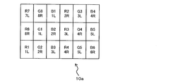
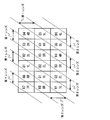
- FIG. 2 is a diagram illustrating an example of an array of display elements of the display device 10. is there.
- the viewer is positioned so as to face the display device 10 having the lens sheet 11 attached to the display surface 10a (see FIG. 10) (see FIG. 23).
- a stereoscopic display image is displayed on the surface 10a.
- the stereoscopic display image is formed on the left and right eyes of the viewer via the lens sheet 11, and the stereoscopic image of the display object is visually recognized.
- the stereoscopic image display device 1 as an example of the first embodiment is a lens-type stereoscopic image display device that realizes a viewer's stereoscopic vision with the lens sheet 11.
- the stereoscopic display image (3D image) is, for example, an image taken by two adjacent cameras. Of these two cameras, an image from one camera is used as an image for the left eye, and an image from the other camera is used. Used as an image for the right eye.
- the stereoscopic display image includes a left-eye image and a right-eye image. Stereoscopic viewing is possible with these two images having binocular parallax. Note that the stereoscopic display image can be created using various known methods, and detailed description thereof is omitted.
- the stereoscopic display image displayed on the stereoscopic image display device 1 may be a moving image or a still image.
- the stereoscopic image display device 1 as an example of the embodiment includes a display device 10, a lens sheet 11, a camera pair 12, and a display control device 13.
- the display device 10 is, for example, a liquid crystal display, and displays an image on the display surface 10 a according to control from the display control unit 12. That is, in the stereoscopic image display device 1, a stereoscopic display image is displayed on the display device 10.
- the display device 10 is a liquid crystal display will be described.
- the display surface 10a of the display device 10 is formed as a flat surface, and a plurality of color pixel elements (display elements) are arranged on the display surface 10a in the horizontal direction (horizontal direction in FIG. 2; arrangement direction) of the display surface 10a. They are arranged in a vertical direction (vertical direction in FIG. 2) perpendicular to the direction. That is, on the display surface 10a of the display device 10, the display elements are arranged in a matrix by arranging the display elements in an arrangement direction and a direction orthogonal to the arrangement direction.
- a plurality of pixels constituting an image (stereoscopic image) displayed on the display surface 10a is represented by a display element (display element).
- each pixel includes a plurality of color pixels.
- An example of the color pixel is a color pixel that forms the three primary colors of light of red (R; Red), green (G; Green), and blue (B; Blue).
- the display elements of these color pixels are repeatedly arranged in a predetermined order in the arrangement direction.
- display elements of the same type are continuously arranged in a direction orthogonal to the arrangement direction.
- a black matrix may be arranged at the boundary between the display elements.
- one pixel is represented by display elements of three consecutive color pixels of R, G, and B.
- the display element of each color pixel is a rectangular display element in which the light emitting portion has a rectangular shape.
- R, G, B arranged (continuous) in an oblique direction (non-parallel direction) with respect to the vertical direction of the array of display elements on the display surface 10 a as illustrated in FIG. 2.
- Each pixel is represented by a display element of three color pixels. That is, one pixel is arranged in an oblique direction.
- R1, G1, and B1 that are display elements of color pixels form one pixel (pixel L1).
- the color pixel of one pixel is arranged non-parallel to the pixel arrangement direction (horizontal direction in the present embodiment), but the present invention is not limited to this. However, various modifications can be made.
- the color pixel of one pixel may be arranged in parallel to the pixel arrangement direction.
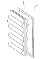
- FIG. 3 is a diagram illustrating a configuration example of the lens sheet 11 of the stereoscopic image display device 1 as an example of the first embodiment.
- the lens sheet 11 includes a plurality of (two in the example shown in FIG. 3) optical units 104 and 106 and is disposed facing the display surface 10 a of the display device 10.
- the optical unit 104 may be referred to as a first optical unit 104
- the optical unit 106 may be referred to as a second optical unit 106.
- the display surface 10 a and the optical units 104 and 106 are arranged so as to be substantially parallel, and the display unit 10 a, the first optical unit 104, and the second optical unit 106 are arranged in this order.
- the first optical unit 104 is a lenticular lens (lenticular lens) including a plurality of kamaboko-shaped first lenses (lens array) and a flat surface on the surface facing the display device 10.
- the outer surface of the first optical unit 104 (the surface opposite to the surface facing the display device 10) is a flat surface.
- the outer surface of the first optical unit 104 may be in contact with the second optical unit 106.
- the first lens and the plane portion are disposed so as to be oblique to the pixel array (display element array) on the display surface 10 a of the display device 10.
- the first lens has a diagonal line parallel to three display elements (diagonal display element group) positioned in an oblique direction forming one pixel in the display device 10 described above. It arrange
- the second optical unit 106 is a lenticular lens including a plurality of second lenses (lens array) having a semi-cylindrical shape on a surface opposite to the side facing the display device 10 and a plane portion.
- the outer surface of the second optical unit 106 (the surface facing the display device 10) is a flat surface.
- the second lens and the plane portion are also arranged so as to be inclined with respect to the pixel array of the display surface 10a of the display device 10.
- the second lens is arranged so that its generatrix is parallel to the oblique display element group in the display device 10 described above and overlaps with these oblique display element groups.
- the entire surface of the first optical unit 104 and the second optical unit 106 may be protected by a transparent flat plate.
- the lenses used in the first optical unit 104 and the second optical unit 106 are kamaboko-shaped curved lenses.
- the lenses used in the first optical unit 104 and the second optical unit 106 are convex portions in the first optical unit 104 and the second optical unit 106.
- the shape of the kamaboko-shaped curved lens is, for example, one of the portions surrounded by the closed curve and the straight line when a closed curve (for example, an ellipse) on the plane is cut by the plane straight line, It is a three-dimensional shape that can be formed when scanning in the line direction.
- the shape of the kamaboko-shaped curved lens may be, for example, one three-dimensional shape obtained by cutting a cylinder (or elliptical cylinder) along a plane parallel to a straight line in the height direction of the cylinder (elliptical cylinder). Further, the first optical unit 104 and the second optical unit 106 may be integrated or separated.
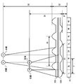
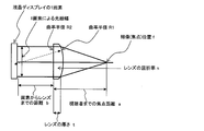
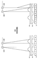
- FIG. 4 is a diagram illustrating a cross section of the lens sheet 11 in the stereoscopic image display device 1 as an example of the first embodiment. As shown in FIG. 4, the distance between the display device 10 and the principal point of the first lens of the first optical unit 104 is G1, and the distance between the display device 10 and the output point of the second lens of the second optical unit 106 is G2.
- the distance between the principal point of the first lens and the position where the image of the display device 10 is imaged through the first lens is D1
- the position of the principal point of the second lens and the image of the display device 10 is imaged through the second lens.
- the focal length of the first lens is a distance f1
- the focal length of the second lens is a distance f2.
- the focal length of the lens is obtained from the lens material and the radius of curvature.
- the first lens of the first optical unit 104 and the planar part of the second optical unit 106 are disposed so as to substantially overlap.
- the light emitted from the display device 10 passes through the first lens of the first optical unit 104, passes through the flat part of the second optical unit 106, and reaches the viewer's eyes.
- the planar portion of the first optical unit 104 and the second lens of the second optical unit 106 are disposed so as to substantially overlap.
- the light emitted from the display device 10 passes through the flat portion of the first optical unit 104, passes through the second lens of the second optical unit 106, and reaches the viewer's eyes.
- the light passing through the first lens of the first optical unit 104 is not affected by the second lens of the second optical unit 106 by passing through the plane part of the second optical unit 106.
- the light passing through the second lens of the second optical unit 106 is not affected by the first lens of the first optical unit 104 by passing through the flat portion of the first optical unit 104.
- 1L and 3L images (pixels) of the display device 10 are incident on the left eye of the viewer at the position where the image of the display device 10 is imaged through the first lens.
- the 1R and 3R images of the display device 10 are incident on the right eye of the viewer at the position where the image of the display device 10 is imaged through the first lens.
- the 2L and 4L images of the display device 10 are incident on the left eye of the user existing at a position where the image of the display device 10 is imaged through the second lens.
- the 2R and 4R images of the display device 10 are incident on the right eye of the viewer at the position where the image of the display device 10 is imaged through the second lens. The same applies to the depth direction and the left-right direction in FIG.
- the pixels of 1L and 2L, 1R and 2R, 3L and 3L, 3R and 4R may be common, respectively. That is, for example, 1L and 2L pixels may be common.
- the same formula is established between the distance D2, the distance G2, and the distance f2. Therefore, by adjusting the distances G1, G2, f1, and f2, the viewer position D1 and the distance D2 can be determined.
- the sum of the distance D1 and the distance G1 is set to be different from the sum of the distance D2 and the distance G2. By setting in this way, the viewer can visually recognize the stereoscopic image displayed on the display device 10 from a plurality of positions.
- the sum of the distance D1 and the distance G1 is the distance between the display surface 10a of the display device 10 and the viewer who views the stereoscopic image through the first lens.
- the sum of the distance D2 and the distance G2 is the distance between the display surface 10a of the display device 10 and the viewer who views the stereoscopic image through the second lens.
- the interval between the first lenses in the first optical unit is determined by the following equation.
- the distance between the first lens that receives light from the 1L pixel and the first lens that receives light from the 3L pixel is defined as a distance Q1.
- the distance between the first lens that receives light from the 1L pixel and the first lens that receives light from the 1R pixel is half of the distance Q1.
- the distance between the first lens that receives light from the 2L pixel and the second lens that receives light from the 4L pixel is defined as a distance Q2.
- the distance between the second lens that receives light from the 2L pixel and the second lens that receives light from the 2R pixel is half of the distance Q2.
- the distance between the 1L pixel and the 1R pixel in the display device 10 is a distance P.
- the distance between the 1L pixel and the 2L pixel in the display device 10 is half of the distance P.
- n is a fixed value depending on the material constituting the lens. Therefore, f is determined depending on r1.
- FIG. 6 is a diagram illustrating the arrangement of the first lens and the second lens and the pixels on the display surface 10 a of the display device 10.
- the pixels shown in FIG. 6 are some of the pixels on the display surface 10 a of the display device 10.
- Each pixel (1L, 2L, etc.) has R, G, and B color pixels, respectively.
- one pixel (1L) is formed by R1, G1, and B1 in FIG.
- a left-eye pixel is displayed by pixels such as 1L and 2L. 1L, 2L, etc. are pixels for the left eye.
- pixels for the right eye are displayed by pixels such as 1R and 2R. 1R, 2R, etc. are pixels for the right eye.
- pixels of the left-eye image are displayed on the display element used for displaying the left-eye image. Further, the pixels of the right eye image are displayed on the display element used for displaying the right eye image.
- the first lens and the second lens are arranged in an oblique direction (non-parallel direction) with respect to the vertical direction of the array of display elements of the display device 10.
- the first lens and the second lens are arranged in parallel to the direction of the other lens.
- each pixel displayed on the display device 10 arranges color pixels in an oblique direction. That is, one pixel is arranged in an oblique direction. For example, color pixels R1, G1, and B1 form one pixel. Similarly, the same applies to other color pixels.
- the direction of the first lens and the second lens is parallel to the three display elements (diagonal display element group) positioned in the oblique direction forming one pixel, whereby the direction of the color pixel in each pixel and each direction It is parallel to the direction of the lens.
- light emitted from 1L and 1R pixels is incident on the first lens.
- the light emitted from the 2L and 2R pixels is incident on the second lens.
- Each pixel is formed by a display element on the display surface 10 a of the display device 10.
- a display control device 13 to be described later performs light emission control of each display element provided on the display surface 10 a of the display device 10.
- FIG. 7 is a diagram illustrating an example when the viewpoint moves.
- the viewer On the left side of FIG. 7, the viewer is in a position where the images from 2L and 2R are imaged by the left and right eyes, watching the 2L image with the left eye and watching the 2R image with the right eye. Accordingly, the viewer can visually recognize the stereoscopic image by viewing the left-eye image with the left eye and the right-eye image with the right eye.
- the position of the viewer's left eye is at the position where the image from 2R, which is the image for the right eye, forms an image.
- the right image is visually recognized by the viewer's left eye.
- the position of the right eye of the viewer is not at a position where any image from the display device 10 is formed.
- the image from 3L since the image from 3L is formed in front of the viewer, it cannot be viewed with the viewer's right eye.
- the viewer's right eye can only see a blurred image. Accordingly, the viewer can view a stereoscopic image with both eyes by moving to the left or right. Therefore, the viewer does not visually recognize the stereoscopic image in the reverse viewing state.
- the reverse viewing state is a state in which the left eye sees the image for the right eye and the right eye sees the image for the left eye.
- the stereoscopic image display apparatus 1 includes a plurality (two in the example shown in FIG. 2) of optical units 104 and 106 as described above. By laminating the plurality of optical units 104 and 106, a plurality of images displayed on the display device 10 from the display surface 10a of the display device 10 (two in the example shown in FIG. 2). Image at a distance of. Thereby, the viewer of this stereoscopic image display device 1 can visually recognize the stereoscopic image displayed on the display device 10 from a plurality of positions (two in the example shown in FIG. 2).
- the stereoscopic image display device 1 has a front imaging point and a rear imaging point with respect to the display device 10 so that a user who views a stereoscopic image at either imaging point moves to the left or right. Even so, it is possible to prevent reverse viewing.
- the stereoscopic image display device 1 includes a first optical unit 104 having a first lens on the inner side (display device 10 side) and a second optical having a second lens on the outer side (the side opposite to the side facing the display device 10).
- the distances (distances G1, G2) between the lenses and the display device 10 can be greatly varied. That is, the difference between the distance G1 and the distance G2 can be increased.
- the stereoscopic image display apparatus 1 can greatly vary the position (image formation point; the sum of the distance G1 and the distance D1, the sum of the distance G2 and the distance D2) at which the image is formed through each lens.
- FIG. 8 is a diagram illustrating a modification of the first optical unit and the second optical unit.
- the first optical unit 104 and the second optical unit 106 are separated.
- the first optical unit 104 and the second optical unit 106 are combined to form one optical unit. Form. By forming the optical part in this way, the number of parts can be reduced.
- FIG. 9 is a diagram illustrating a modification of the optical unit and the display device.
- the lens sheet 11 includes a first optical unit 204, a second optical unit 206, and a third optical unit 208. That is, the lens sheet 11 includes three optical parts.
- the first optical unit 204, the second optical unit 206, and the third optical unit 208 have the same configuration as the first optical unit 104 and the second optical unit 106.
- the lens sheet 11 has three optical parts.
- the present invention is not limited to this, and the lens sheet 11 may have four or more optical parts.
- the apparatus having this configuration includes a plurality (n) of optical units, so that an image from the display surface 10a can be obtained at a plurality (n types) of distances (imaging positions) from the display surface 10a of the display device. Can be imaged.
- the number of optical parts may be referred to as the number of images.
- Each optical part in this modification has a flat part so that light passing through the lenses of other optical parts does not pass through its own lens.
- the distance between the lenses that is, the width of the flat part is substantially equal to a value obtained by multiplying the lens width by (n ⁇ 1). Therefore, each optical part in this modification has a larger planar part than the planar part in the optical part of the above embodiment.
- the surface on which the lens in each optical unit exists may be on the display device 10 side, or on the opposite side of the surface facing the display device 10.
- the focal length of the lens array varies depending on the distance between the light emitting pixel and the curved surface of the lens array due to its optical structure. For this reason, even if the lens curved surface is on the display device 10 side or the viewer side, there is no effect on the image formation.
- the stereoscopic image display device 1 it is possible to form a stereoscopic image on the viewer's eyes at each of a plurality of positions at different distances from the display surface 10a of the display device 10.
- each display pixel on the display surface 10a forms an image at a focal length corresponding to the configuration of the optical unit of the lens sheet 11 arranged facing the display pixel. That is, each display pixel on the display surface 10a is specified to display either a right-eye image or a left-eye image, and any one of a plurality of focal lengths of the lens sheet 11 is included. It is specified in the image formation.
- each display pixel on the display surface 10a is associated with either the right-eye image or the left-eye image in advance, and any one of the focal lengths of the lens sheet 11 is included. Is associated with.
- a display element used for displaying a right eye image is referred to as a right eye display element
- a display element used for displaying a left eye image is referred to as a left eye display element.
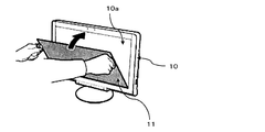
- FIG. 10 is a diagram illustrating an example of attachment of the lens sheet to the display device in the stereoscopic image display device as an example of the first embodiment.
- the lens sheet 11 is fixedly attached to a predetermined position in front of the display surface 10 a of the display device 10 (viewer side).
- the lens sheet 11 is attached to the display device 10 by, for example, fixing it to a hook or the like (not shown).
- the display device 10 is provided with a sensor (not shown) that detects attachment of the lens sheet 11, and notifies the display control device 13 of information on whether or not the lens sheet 11 is attached.
- the lens sheet 11 is provided with a 3D panel ID (identification information) for identifying the type of the lens sheet 11 and the like.
- the lens sheet 11 may be referred to as a 3D panel.
- the lens sheet 11 is provided with a non-contact ID tag storing a 3D panel ID
- the display device 10 is provided with an ID tag reader, whereby the display device 10 can acquire the 3D panel ID. Further, the display device 10 transmits the acquired 3D panel ID to the display control device 13.
- one lens array (one lens) is made to correspond to one pixel of the display surface 10a, so that the light beam of one pixel does not decrease the light intensity (light quantity) and is accurate.
- An image can be formed with a focal length a.
- the camera pair 12 is an imaging device (imaging unit) that captures the viewer's face.
- the camera pair 12 is attached so as to face the viewer's front position, such as the upper part of the display device 10, and the viewer's face (particularly both Eye).
- the camera pair 12 for example, a web camera provided in a PC (Personal Computer) can be used.
- the camera pair 12 may be embedded in, for example, a frame (not shown) of the display device 10 and the arrangement thereof can be changed as appropriate.
- the camera pair 12 includes two imaging devices, a first camera 12a and a second camera 12b.
- the first camera 12a and the second camera 12b are arranged side by side in the horizontal direction at the same height and at the same distance from the viewer.
- the first camera 12a and the second camera 12b are desirably arranged in a frame or the like of the display device 10 or attached externally.
- the first camera 12a may be referred to as a left camera
- the second camera 12b may be referred to as a right camera.
- An image captured by the camera pair 12 is transmitted to the display control device 13.
- the camera pair 12 preferably continuously transmits the captured image to the display control device 13 when displaying a stereoscopic image.
- the viewer is imaged using the camera pair 12, and a distance measurement processing unit 31 described later measures the distance between the display surface 10 a of the display device 10 and the viewer.
- FIG. 11 is a diagram schematically illustrating a hardware configuration of the display control device 13 of the stereoscopic image display device 1 as an example of the first embodiment.
- the display control device 13 includes, for example, a CPU (Central Processing Unit) 131, a LAN (Local Area Network) card 132, a tuner 133, a graphic accelerator 134, a chip set 135, a memory 136, and an audio controller 137.
- a keyboard controller 140 including a keyboard controller 140.
- the graphic accelerator 134 is an image display control interface that is connected to the display device 10 and causes the display device 10 to display an image. Note that the chip set 135 may have a function as the graphic accelerator 134.
- the LAN card 132 is an interface card for connecting to a network such as the Internet, and the tuner 133 is connected to the external antenna 142, receives a TV program, performs processing such as decoding, and causes the display device 10 to display it as image data.
- the memory 136 is a storage device such as a RAM (Random Access Memory) and a ROM (Read Only Memory), and stores various programs and data that are executed or used by the CPU 131.
- the audio controller 137 is connected to a speaker 143 and controls output of audio data to the speaker 143.
- the HDD 138 is a storage device, and stores an OS (Operating System) executed by or used by the CPU 131, various programs, data, and the like.
- the HDD 138 and the memory 136 also store various image (two-dimensional image, three-dimensional (three-dimensional) image) data displayed on the display device 10.
- the HDD 138 stores stereoscopic image data created in advance for a stereoscopic display target (display target), as will be described later. That is, the HDD 138 functions as a storage unit that stores parallax images having different parallax amounts with respect to a display target.
- the HDD 138 stores a distance measurement table (range measurement correspondence information; see FIG. 16) 41 described later.
- the Blu-ray disc drive 139 plays a Blu-ray disc.
- Various image data displayed on the display device 10 may be stored on the Blu-ray disc.
- a reproducing apparatus capable of reproducing a recording medium other than the Blu-ray disc (for example, a DVD) may be provided, and various image data stored in the recording medium may be reproduced.
- the keyboard controller 140 is connected to input devices such as a keyboard 144 and a mouse 145, and controls data exchange between the keyboard 144 and mouse 145 and the CPU 131. These units are connected to the chip set 135 via a bus or the like, and control communication between the CPU 131 and these units.
- a camera pair 12 is also connected to the display control device 13, and receives an image of the viewer's face captured by the camera pair 12.
- the CPU 131 is a processing device that implements various functions by executing programs stored in the HDD 138 and the memory 136.
- the CPU 131 displays content such as a moving image or a still image on the display surface 10a of the display device 10 by executing an image reproduction application, for example.
- the CPU 131 functions as a distance measurement processing unit 31, a selection unit 32, and a display control unit 33 as illustrated in FIG. 1.
- the above-described image reproduction application includes functions as the distance measurement processing unit 31, the selection unit 32, and the display control unit 33.
- a program (image reproduction application) for realizing the functions as the distance measurement processing unit 31, the selection unit 32, and the display control unit 33 is, for example, a flexible disk, a CD (CD-ROM, CD-R, CD-). RW, etc.), DVD (DVD-ROM, DVD-RAM, DVD-R, DVD + R, DVD-RW, DVD + RW, etc.), Blu-ray disc, magnetic disc, optical disc, magneto-optical disc, etc. Provided in the form. Then, the computer reads the program from the recording medium, transfers it to the internal storage device or the external storage device, and uses it.
- the program may be recorded in a storage device (recording medium) such as a magnetic disk, an optical disk, or a magneto-optical disk, and provided from the storage device to the computer via a communication path.
- a program stored in an internal storage device (memory 136 in the present embodiment) is stored in a microprocessor of the computer (in this embodiment).
- CPU 1331 the computer may read and execute the program recorded on the recording medium.
- the computer is a concept including hardware and an operating system, and means hardware that operates under the control of the operating system. Further, when an operating system is unnecessary and hardware is operated by an application program alone, the hardware itself corresponds to a computer.
- the hardware includes at least a microprocessor such as a CPU and means for reading a computer program recorded on a recording medium.
- the stereoscopic image display apparatus 1 has a function as a computer. It is doing.
- the distance measurement processing unit 31 measures the distance from the display surface 10 a of the display device 10 to the viewer based on the image captured by the camera pair 12.
- the distance measurement processing unit 31 acquires viewer images captured by the two imaging units of the first camera 12a and the second camera 12b, and views them based on the shift amounts (dots, parallax amounts) of these images. The distance to the person is calculated.
- FIG. 12 is a diagram illustrating the positional relationship between the camera pair 12 and the imaging target in the stereoscopic image display device 1 as an example of the first embodiment.
- the first camera 12 a and the second camera 12 b are frames of the display device 10, and are built in a position facing the viewer at a substantially central position of the display device 10.
- the distance between the first camera 12a and the second camera 12b with respect to the viewer is constant. That is, the first camera 12a and the second camera 12b are arranged at different positions in the horizontal direction at a position equidistant from the object.
- the two cameras, the first camera 12a and the second camera 12b capture images with a focus on an object (reference object) at a reference position that is a predetermined distance away from the display surface 10a of the display device 10, respectively.
- An image (video frame) of a reference object captured by the first camera 12a and the second camera 12b is referred to as a reference image.
- the imaging object is, for example, a viewer.
- the distance measurement processing unit 31 superimposes the reference images captured from the first camera 12a and the second camera 12b, respectively, and matches the reference objects in these reference images.
- the distance measurement processing unit 31 stores the distance from the display surface 10a of the display device 10 to the reference position in the HDD 138 as reference viewpoint position information.
- the distance between the display surface 10a of the display device 10 and the object that is, the first camera 12a and the second camera 12b and the object.
- the amount of parallax in the horizontal direction varies depending on the distance.
- the distance measurement processing unit 31 measures the amount of parallax in the horizontal direction of the object between these video frames based on the video frames of the viewers captured by the first camera 12a and the second camera 12b, respectively.
- the distance measurement processing unit 31 determines the distance from the display surface 10a to the viewer by referring to the distance measurement table 41 (see FIG. 16) registered in advance based on the measured amount of parallax.
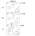
- FIGS. 13A, 13B, and 13C are diagrams illustrating the relationship between the position of the object and the image of the object photographed by the camera pair 12.
- FIG. 13A illustrates an image frame L00 in which three objects are photographed by the first camera 12a (left camera). Images of the photographed objects are indicated by alternate long and short dash lines and denoted by reference numerals L1 to L3.
- FIG. 13B illustrates an image frame R00 in which three objects are photographed by the second camera 12b (right camera). Images of the photographed objects are indicated by broken lines and denoted by reference numerals R1 to R3.
- Show. 13C shows an image frame P00 obtained by synthesizing the image of FIG. 13A and the image of FIG.
- symbol A represents the viewer at the reference viewpoint position.
- symbol B indicates an object located at a position farther than the reference viewpoint position with respect to the display device 10.
- Reference symbol C indicates an object located closer to the display device 10 than the reference viewpoint position.
- the object is indicated by a rectangle or a circle for convenience.
- the image R1 of the object A photographed by the right camera matches the image L1 of the object A photographed by the left camera, and the amount of horizontal parallax is zero ( Hereinafter, the parallax amount is zero).
- the image L3 captured by the left camera is shifted to the right in the horizontal direction due to reverse parallax with respect to the image R3 captured by the right camera.
- the image L2 captured by the left camera is shifted to the left in the horizontal direction with respect to the image R2 captured by the right camera.
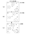
- FIGS. 14A, 14 ⁇ / b> B, and 14 ⁇ / b> C are diagrams illustrating the relationship between the position of the object and the image of the object captured by the camera pair 12, and FIGS. 13A, 13 ⁇ / b> B, and 13 ⁇ / b> C are illustrated.
- the image frames L01, R01, and P01 in a state where the object A in the state of c) approaches the display device 10 side are illustrated.
- FIGS. 15A, 15B, and 15C are also diagrams illustrating the relationship between the position of the object and the image of the object photographed by the camera pair 12, and FIGS. , (C) illustrates image frames L02, R02, and P02 in a state in which the object A is away from the display device 10 side.
- the amount of deviation in the horizontal direction of the images R1 and L1 of the object A depends on the distance between the display surface 10a of the display device 10 and the object A. Therefore, the distance between the display surface 10a of the display device 10 and the object A can be detected by measuring the amount of deviation.
- the amount of deviation is measured by comparing the image L1 of the object A in the image frames L01 and L02 with the image R1 of the object A in the image frames R01 and R02. That is, the distance measurement processing unit 31 compares the image R1 of the object A measured by the second camera 12b with the image L1 of the object A measured by the first camera 12a, and between these images R1 and L1. Detects the horizontal dot difference (deviation amount).
- the distance measurement processing unit 31 detects the dot difference using, for example, the image of the viewer's eyes or one eye as the image of the object A. For example, when an image of the viewer's eyes is used, a line segment connecting both sides can be used.
- the amount of deviation measured by the distance measurement processing unit 31 is stored in a predetermined storage area such as the memory 136.
- FIG. 16 is a diagram illustrating a distance measurement table 41 of the stereoscopic image display device 1 as an example of the first embodiment.
- the distance measurement table 41 is distance measurement information that associates a dot difference between an image from the right camera and an image from the left camera with respect to an object and a distance to the object (viewer).
- the distance measurement table 41 is shown as a table in which the viewer distance and the parallax amount range are associated with each other.
- the viewer distance is the distance between the display surface 10a of the display device 10 and the viewer.
- the parallax amount range indicates a dot difference corresponding to the viewer distance as a range between an upper limit value and a lower limit value. For example, when the dot difference is a value in the range of 17 to 23, the viewer distance is 1.8 m. That is, the distance measurement table 41 is reference data for determining the distance from the display device 10 to the viewer based on the detected dot difference.
- the distance measurement processing unit 31 obtains a dot difference between an image captured by the right camera and an image captured by the left camera for the viewer, and which parallax amount range in the distance measurement table 41 corresponds to the dot difference. Judgment is made, and the viewer distance corresponding to the corresponding parallax amount range is determined.
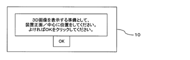
- FIG. 17 is a diagram illustrating a dialog box in the stereoscopic image display device 1 as an example of the first embodiment.
- the viewer faces the display device 10 (camera pair 12) at a position where the distance from the display device 10 is defined in advance, and operates the keyboard 144 and mouse 145 to “OK”. Select.
- the distance measurement processing unit 31 detects the dot difference between the images of the viewer's eyes taken by the first camera 12a and the second camera 12b, and refers to the distance measurement table 41 based on the dot difference. Determine the distance to the viewer.
- the distance measurement processing unit 31 may use the position of the viewer when “OK” is selected according to the dialog box shown in FIG. 17 as the reference position. That is, the distance measurement processing unit 31 matches the viewer images captured by the first camera 12a and the second camera 12b at the reference position as reference images. As described above, the first camera 12a and the second camera 12 incorporated in the display device 10 with a certain distance from the viewer each image the viewer as an object. Then, the distance measurement processing unit 31 recognizes the viewer as an object in the video frames input simultaneously by the first camera 12a and the second camera 12b, and displays them according to the parallax amount of the object in these left and right images. The distance from the surface 10a to the viewer is detected. This makes it possible to detect the viewer's viewpoint position easily and at low cost. Thus, in the stereoscopic image display device 1, the distance between the display surface 10 a of the display device 10 and the viewer is detected as sensor information by the camera pair 12.
- the distance measurement processing unit 31 cannot detect the viewer in the video frame received from the camera pair 12 or detects that the dot difference is out of the range of the distance measurement table 41, the normal viewer viewing range.
- the selection unit 32 is notified of this (notification of viewer outside normal viewing range). This is because, outside the viewer distance range of the distance measuring table 41, the lens sheet 11 cannot focus on the viewer's eyes, and stereoscopic viewing cannot be realized.
- the selection unit 32 sets the level value from the HDD 138 according to the distance measured by the distance measurement processing unit 31.
- the corresponding stereoscopic display image (left eye stereoscopic display image and right eye stereoscopic display image) is selected.
- the selection unit 32 selects an image corresponding to the distance from the display surface 10 a to the viewer from a plurality of images stored in the HDD 138 and having different 3D effects on the display target, and causes the display device 10 to display the selected image. .
- FIGS. 18A, 18 ⁇ / b> B, and 18 ⁇ / b> C are diagrams for explaining an image (stereoscopic image) used in the stereoscopic image display device 1 as an example of the first embodiment.
- FIG. 18A is a diagram exemplifying display target image data for performing stereoscopic display, and is image data having a triangular display target Ob1 on the front side of the rectangular display target Ob2.
- 18B is a diagram illustrating stereoscopic image data related to the image data shown in FIG. 18A, and FIG. 18C illustrates two-dimensional image data of the image data shown in FIG. FIG.
- the stereoscopic image display apparatus 1 has a plurality of images with different 3D effects for one display target (see FIG. 18A). Specifically, a combination of a right-eye stereoscopic display image (right-eye image) and a left-eye stereoscopic display image (left-eye image) with respect to one display target as stereoscopic image data in the HDD 138 ( As a stereoscopic display image pair), a combination of a plurality of parallax images having different binocular parallax amounts is provided.
- the left-eye stereoscopic display image and the right-eye stereoscopic display image are provided with a predetermined binocular parallax.
- the left-eye stereoscopic display image is formed on the left eye and the right-eye stereoscopic display image is formed on the right eye, and the stereoscopic display image is stereoscopically displayed. It can be visually recognized.
- a plurality of viewpoints with parallax are referred to as parallax points, respectively.
- the stereoscopic image display apparatus 1 realizes binocular parallax stereoscopic vision using binocular parallax, and the viewer's right eye and left eye are parallax points, respectively.
- the HDD 138 stores a parallax image for the left eye and a parallax image for the right eye that are created with parallax with respect to each of the left eye and the right eye as parallax points. Then, by combining the left-eye parallax image and the right-eye parallax image, a stereoscopic display image pair (3D image) is generated.
- a stereoscopic display image pair (3D image) is generated.
- 3D display makes a viewer visually recognize a stereoscopic image by forming a parallax image having binocular parallax with the right eye and the left eye.
- the parallax image N1 is a parallax image that forms an image on one of the left eye and the right eye, and the parallax images N2 to N4 are displayed. Is a parallax image formed on the other eye.
- the parallax image N1 is a parallax image for the left eye and the parallax images N2 to N4 are parallax images for the right eye will be described.
- the parallax image N1 may be used as a parallax image for the right eye
- the parallax images N2 to N4 may be used as parallax images for the left eye.
- the parallax images N2, N3, and N4 are multi-view stereoscopic image data having different binocular parallax amounts with respect to the parallax image N1.
- the binocular parallax amount with respect to the parallax image N1 is the largest in the parallax image N4 and decreases in the order of the parallax image N3 and the parallax image N2.
- the parallax images N1, N3, and N4 are selected and combined as a stereoscopic display image pair for stereoscopic viewing, the stereoscopic effect is obtained by combining these parallax images. (Stereoscopic effect) is different.
- stereoscopic display image pairs (3D images) 1, 2, and 3 are generated by selectively combining the parallax images N2, N3, and N4 with respect to the parallax image N1.
- the 3D image 3 in which the parallax image N4 having the largest binocular parallax amount is combined with the parallax image N1 is the most targeted for the viewer when displayed on the display device 10. Things appear to pop out.
- the selection unit 32 selects a stereoscopic display image pair having a larger binocular parallax amount as the viewer distance detected by the distance measurement processing unit 31 is shorter, and a stereoscopic image having a smaller binocular parallax amount as the viewer distance is longer. Select a display image pair. As a result, the viewer can visually recognize the stereoscopic display image that has jumped out greatly as the viewer distance is short, and can view the stereoscopic display image with a small pop-out amount as the viewer distance increases.
- the triangle Ob1 is the closest data as the 3D image format data. Therefore, in the stereoscopic display image pair, the binocular parallax of the triangle Ob1 is larger than the binocular parallax of the quadrangle Ob2.
- the parallax image N1 is displayed as a group of pixels that form an image on the left eye and the parallax image N4 is displayed as a group of pixels that forms an image on the right eye, the triangle Ob1 pops out most to the viewer. Visible.
- the number of parallax images is not limited to four of N1 to N4 shown in FIG. 18B, and five or more parallax images may be provided.
- the parallax image is converted into 3D image information by adding information in the Z direction (depth direction) to the 2D image after demultiplexing the 3D image format data, and further rendering is performed. Created by doing. At this time, various parallax images can be generated by arbitrarily changing the Z direction information added to the 2D image.
- the selection unit 32 selects a parallax image to be combined with the parallax image N1 as a stereoscopic display image pair from among a plurality of (three in the example illustrated in FIG. 18B) parallax images N2 to N4 with respect to the display target.
- a plurality of types of 3D images 1, 2, and 3 are generated.
- the viewer distance (see FIG. 16) is associated with each of the parallax images N2 to N4 combined with the parallax image N1.
- the selection unit 32 generates a 3D image corresponding to the viewer distance by selecting a parallax image corresponding to the determined viewer distance.
- the selection unit 32 reduces the amount of parallax when the viewer is far from the display surface 10a by selecting and displaying different 3D images according to the distance between the display surface 10a of the display device 10 and the viewer. When approaching, increase the amount of parallax.
- the selection unit 32 appropriately selects a parallax image to be combined with the parallax image N1, and displays these selected parallax images on the left eye and the right eye, so that the 3D feeling and It becomes possible to control the 3D effect. That is, a pixel array (image) for 3D imaging having an optimal parallax according to the viewer's viewpoint position (distance) is selected from multi-view stereoscopic image data composed of images synchronized with a display target. To do.
- the viewer distance may be associated with the combination of the parallax image N1 and the parallax images N2 to N4.
- the parallax images N1 to N4 can be created using various methods. For example, a plurality of parallax images N1 to N4 having binocular parallax may be created by shooting the display object from different positions in the horizontal direction.
- the number of parallax images having different 3D effects that are synchronized with the image data is recorded as the number of synchronized images.
- the number of synchronized images is four.
- the selection unit 32 selects two parallax images corresponding to the viewer distance from these four parallax images as a left-eye image and a right-eye image.
- the selection unit 32 selects the same parallax image (for example, the parallax image N1) for the left-eye image and the right-eye image. .
- the same parallax image for the left-eye image and the right-eye image By displaying the same parallax image for the left-eye image and the right-eye image on the display device 10, the viewer recognizes that a two-dimensional image without parallax is displayed.
- displaying the same parallax image on the display device 10 for the left-eye image and the right-eye image may be expressed as 2D display.
- the selection unit 32 detects that the stereoscopic image display device 1 does not satisfy the environment for reproducing the 3D image, such as when the sensor described above does not detect the attachment of the lens sheet 11 to the display device 10. Also, 2D display is performed. Furthermore, the selection unit 32 may detect that the stereoscopic image display device 1 does not satisfy the environment for reproducing the 3D image by using a model ID or the like registered in advance in the display control device 13, for example. Can be implemented.
- the display control unit 33 performs control to display the stereoscopic display image selected by the selection unit 32 on the display device 10.
- the display control unit 33 displays two parallax images selected as the left-eye image and the right-eye image by the selection unit 32 on the display surface 10 a of the display device 10 at the same time.
- the display control unit 33 causes the left eye image to be displayed on the display element for the left eye used for displaying the image for the left eye on the display surface 10a, and the right eye used for displaying the image for the right eye.
- the image for the right eye is displayed on the display device.
- the display control unit 33 displays a left-eye image and a right-eye image using a display element corresponding to a focal length corresponding to the viewer distance among the display pixels on the display surface 10a of the display device 10. .
- the pixels constituting the stereoscopic display image are displayed in correspondence with the display elements on the display surface 10a.
- the method of displaying an image on the display device 10 can be realized by using various known methods, and detailed description thereof is omitted.
- the pixel group arrangement of the display unit 10a of the display device 10 in the stereoscopic image display device 1 will be described.
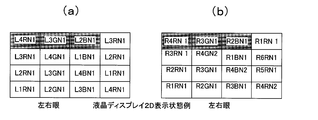
- FIGS. 19A and 19B and FIGS. 20A and 20B are diagrams illustrating examples of display states of the display surface 10a of the stereoscopic image display device 1 as an example of the embodiment.
- FIG. 19A is a diagram illustrating the left-eye display element in the 2D display state
- FIG. 19B is a diagram illustrating the right-eye display element in the 2D display state.
- FIG. 20A is a diagram illustrating the left eye display element in the 3D display state
- FIG. 20B is a diagram illustrating the right eye display element in the 3D display state.
- the lens sheet 11 is provided with four types of lens arrays (four optical units) having viewer distances of 1.0 m, 1.4 m, 1.8 m, and 2.2 m.
- the example which is a lens sheet of a view (view) is shown. That is, it has a lens array that has images in different horizontal ranges of four views on the left and right.
- FIGS. 19A and 19B When the display device 10 of the stereoscopic image display device 1 performs 2D display, as shown in FIGS. 19A and 19B, three display elements (R, G, B) that are continuous in the horizontal direction are used. Is used to display one pixel.
- FIG. 19B one pixel of the right-eye image is represented by the display elements (R4RN1, R3GN1, R2BN1).
- one pixel is displayed using three display elements (R, G, B) that are continuous in an oblique direction.
- the display element constituting one pixel has a slope that is lowered to the right.
- the present invention is not limited to this, and may be changed as appropriate.
- An example in which the parallax image N1 shown in FIG. 18B is imaged on the left eye and the parallax image N2 on the right eye is shown.
- the pixels L1 to L4 are pixels of the left eye image
- the pixels R1 to R4 are pixels of the right eye image.
- the light emitted from the pixels L4 and R4 passes through a lens array (1.0 m lens array) that forms an image at a distance of 1.00 m from the display surface 10a.
- a lens array 1.4m lens array
- light emitted from the pixels L2 and R2 is displayed on the display surface. It passes through a lens array (1.8m lens array) that forms an image at a distance of 10m to 1.8m.
- the light emitted from the pixels L1 and R1 passes through a lens array (2.2m lens array) that forms an image at a distance of 2.2m from the display surface 10a.
- the display control unit 33 displays the pixel group of the parallax image by performing control to cause only the display element of the lens array corresponding to the viewer distance detected by the distance measurement processing unit 31 to emit light.
- the display control unit 33 causes only the display elements corresponding to the 1.0 m lens array in FIGS. 20A and 20B to emit light to display the pixel group of the parallax image.
- the display control unit 33 displays a display corresponding to a lens array (for example, a 1.4 m lens array, a 1.8 m lens array, or a 2.2 m lens array) that does not correspond to the viewer distance detected by the distance measurement processing unit 31.
- the light emission of the element is suppressed. Thereby, unnecessary light does not enter the viewer's eyes, and the viewer can visually recognize a high-quality image.
- the display control unit 33 changes the arrangement of the image data in units of pixels between 2D display and 3D display.
- two-dimensional image display (2D display) is realized by causing the display device 10 to display the same parallax image for the left-eye image and the right-eye image.
- the parallax image common to the left and right eyes used for 2D display is not limited to the parallax image N1, and can be implemented with appropriate changes.
- FIG. 21A and 21B are diagrams illustrating 2D display in the stereoscopic image display device 1 as an example of the first embodiment.
- FIG. 21A is a diagram schematically illustrating a 2D display state in the stereoscopic image display apparatus 1
- FIG. 21B is a diagram schematically illustrating a display state by a conventional display control method.
- the conventional display control method is used in the display device 10 having the lens sheet 11 of the stereoscopic image display device 1
- the conventional display control method is used. think about.
- image display is performed using all display pixels in the display device.
- FIG. 21B when a conventional display control method is used, a multiple image (4 in the example shown in FIG. (Heavy image). At this time, the overlapping images cannot be formed in the eyes of the viewer and are visually recognized in a blurred state by the viewer.
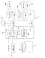
- FIG. 22 is a block diagram schematically illustrating a functional configuration of the stereoscopic image display device 1 as an example of the first embodiment.
- the viewer's face image is captured and output by the camera pair 12 (see reference A10), and then the distance measurement processing unit 31 includes each of the viewers.
- a dot difference (amount of parallax) is detected from the image (see reference A20).
- the distance measurement processing unit 31 refers to the distance measurement table 41 based on the detected dot difference and determines the viewer distance.
- the determined viewer distance is notified to the selection unit 32 as a level notification, and the selection unit 32 selects a stereoscopic display image pair that matches the viewer distance from the HDD 138.
- the display control unit 33 shifts to the reproduction process of the selected stereoscopic display image pair (see reference A30). Further, the level notification may be performed in response to a data request by the selection unit 32.
- the display control unit 33 displays the pixel group of one parallax image forming the stereoscopic display image pair on the display pixel for the right eye in the display device 10 and the other forming the stereoscopic display image pair. Are displayed on the display pixel for the left eye in the display device 10 (see reference A40).
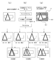
- An outline of a stereoscopic image display method in the stereoscopic image display apparatus 1 as an example of the first embodiment configured as described above will be described with reference to FIG.
- the stereoscopic image display device 1 first, a viewer (particularly eyes) is photographed by the camera pair 12. Images captured by the first camera 12a and the second camera 12b of the camera pair 12 are output and input to the distance measurement processing unit 31 (see reference numeral B10).
- the distance measurement processing unit 31 detects the viewer's eyes from the captured image (see reference B20), and measures the amount of deviation between the images of both eyes.
- the distance measurement processing unit 31 determines the distance between the viewer and the display surface 10a of the display device 10 with reference to the distance measurement table 41 based on the shift amount, and notifies the selection unit 32 (see reference numeral B30). .
- the selection unit 32 selects an image (stereoscopic display image pair, pixel group) displayed on the display device 10 in accordance with the notified distance to the viewer.
- the display control unit 33 displays the stereoscopic display image pair selected by the selection unit 32 using display pixels that form an image at the detected viewer position on the display surface 10a of the display device 10 (reference B40). reference).
- a method for displaying a stereoscopic display image in the stereoscopic image display apparatus 1 according to the first embodiment will be described with reference to the flowchart (steps S10 to S120) shown in FIG.
- FIG. 25 is a diagram illustrating a dialog box in the stereoscopic image display apparatus 1 as an example of the first embodiment.
- the image reproduction application When the image reproduction application is activated in the stereoscopic image display device 1 (step S10), the image reproduction application first confirms whether or not the stereoscopic image display device 1 is a lens-type stereoscopic image display device 1. (Step S20). This confirmation is performed, for example, by confirming a model ID or the like stored in the memory 136 or the HDD 138 of the display control device 13 of the stereoscopic image display device 1.
- step S30 it is confirmed whether or not the lens sheet 11 (3D panel) is attached to the display device 10 (step S30).
- the image reproduction application determines whether or not the lens sheet 11 is attached based on a detection result of a sensor that detects attachment of the lens sheet 11 in the display device 10. As a result of this determination, if the lens sheet 11 is not attached to the display device 10 (see the NO route in step S30), the display device 10 cannot display a stereoscopic image as shown in FIG. A 2D display is performed (step S120).
- Step S40 the arrangement of pixel groups differs depending on the structure of the lens sheet 11 (for example, the number of images formed and the inclination direction of the lens array).
- the display control unit 33 controls the display elements of the display unit 10 according to the confirmed type of the lens sheet 11.
- the distance measurement processing unit 31 detects the amount of parallax between the positions of both pupils based on the face images of the viewers captured by the first camera 12a and the second camera 12b of the camera pair 12 (step S50). The distance measurement processing unit 31 confirms whether the amount of parallax has changed by comparing the amount of parallax of the viewer detected in step S50 with the previous amount of parallax recorded in the memory 136 or the like (step S60). .
- step S60 If no change in the amount of parallax has occurred (see the NO route in step S60), the process returns to step S50. Note that, at the time of initial processing when the stereoscopic image display device 1 is activated, the value stored as the previous amount of parallax is initialized, so it is determined that the amount of parallax has changed. A predetermined design value is appropriately used as the value at the time of initialization.
- the distance measurement processing unit 31 refers to the distance measurement table 41 (reference data) from the display surface 10a of the display device 10 to the viewer.
- Distance viewer distance
- the distance measurement processing unit 31 confirms whether or not the determined distance to the viewer is within the 3D viewing distance range that is previously stored as reference data in the image reproduction application (step S80).
- the selection unit 32 selects the same parallax image for the left-eye image and the right-eye image.
- the display control unit 33 realizes two-dimensional image display (2D display) by causing the display device 10 to display the same selected parallax image (step S110). Thereafter, the process returns to step S50.
- the selection unit 32 selects a stereoscopic display image pair having binocular parallax according to the viewer distance.
- the display control unit 33 switches the selected stereoscopic display image pair to a setting using only the display element (pixel group arrangement) corresponding to the viewer distance in the display device (step S90). That is, the display control unit 33 displays the selected parallax image for the right eye and parallax image for the left eye (3D image content) using only the display elements corresponding to the viewer distance in the display device 10. Thus, 3D display is performed (step S100). Thereafter, the process returns to step S50.
- the distance measurement processing unit 31 measures the amount of deviation of the viewer's image from each video frame taken by the camera pair 12. The distance between the viewer and the display surface 10a of the display device 10 is determined with reference to the distance measuring table 41 based on the deviation amount. Then, the selection unit 32 selects a stereoscopic display image pair having binocular parallax that matches the distance to the viewer. The display control unit 33 displays the stereoscopic display image pair using display pixels that form an image at the detected viewer distance on the display surface 10 a of the display device 10.
- the selection unit 32 selects a stereoscopic display image pair having a larger binocular parallax amount as the viewer distance detected by the distance measurement processing unit 31 is closer, and as the viewer distance is longer, the binocular A stereoscopic display image pair with a small amount of parallax is selected.
- the viewer can see the stereoscopic display image that protrudes larger as the viewer distance is shorter, and can also see the stereoscopic display image that protrudes smaller as the viewer distance is longer. An image effect can be given to the viewer.
- a stereoscopic display image composed of a pair of stereoscopic display images having binocular parallax suitable for the viewer distance can be formed on the viewer's eyes, and a stereoscopic image corresponding to the viewer's viewpoint position is formed.
- I can image.
- the binocular parallax amount decreases in proportion to the distance to the object, and the person is recognized.
- the stereoscopic image display device 1 by changing the image display so that the stereoscopic effect is changed according to the distance from the viewer to the display device 10, it is possible to perform more realistic image expression for the viewer. it can.
- the camera pair 12 always captures an image of the viewer, and the distance measurement processing unit 31 measures the viewer distance and the selection unit 32 selects the stereoscopic display image pair as needed. Thereby, according to the movement of the viewer in front of the display device 10, it is possible to form a stereoscopic display image including a stereoscopic display image pair having binocular parallax according to the position of the viewer.
- the viewer distance based on the viewer's image taken by the camera pair 12. Thereby, it is not necessary to provide a dedicated device for measuring the viewer distance, the viewer distance can be measured at a low cost, and the manufacturing cost can be reduced. At this time, no great load is applied to the CPU 131 or the like.
- the measurement of the viewer distance is not limited to being performed based on an image photographed by the camera pair 12. That is, for example, the viewer distance may be measured using various known sensors.
- the display control unit 33 displays the stereoscopic image pair on the display device 10
- the display control unit 33 displays only the display element corresponding to the viewer distance and suppresses light emission other than the display element corresponding to the viewer distance. To do. Thereby, the image processing load of the CPU 131 and the like in the display control device 13 can be reduced. In addition, the viewer can visually recognize a high-quality stereoscopic image.
- the lens sheet 11 includes a plurality of optical units having a plurality of lenticular lenses, and by laminating these optical units, a plurality of images displayed on the display device 10 are displayed from the display surface 10 a of the display device 10. Image at a distance of. Thereby, the viewer can visually recognize the stereoscopic image displayed on the display device 10 at a plurality of positions away from the display device 10.
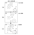
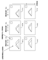
- FIG. 26 is a diagram illustrating a display example of a stereoscopic image when the viewer distance is different in the stereoscopic image display device 1 as an example of the first embodiment.
- the images 41a ′, 41b ′, and 41c ′ shown in the lower stage are respectively obtained after a predetermined time has elapsed from the states of the images 41a, 41b, and 41c shown in the upper stage.
- Each image 41a, 41b, 41c has an object A with reverse parallax information and an object B without parallax information.
- the object A has moved to the left in the figure after a predetermined time.
- the parallax images N1 to N4 shown in FIG. 18B will be described as an example for displaying the same image at different viewing positions.
- a combination (N1 + N2) of the parallax image N1 and the parallax image N2 with the smallest binocular parallax amount is displayed with respect to a focal distance (viewer distance) of 1.8 m.
- N1 + N3 a combination of the parallax image N1 and the parallax image N3 with respect to the viewer distance of 1.4 m
- N1 + N4 a combination of the parallax image N1 and the parallax image N4 with respect to the viewer distance of 1.0 m.
- the distance measurement processing unit 31 detects the position of the viewer, and the selection unit 32 switches the image 41a in the order of the images 41b and 41c.
- the binocular parallax of the object A displayed on the display device 10 increases. Accordingly, the viewer can feel the pop-up of the 3D image of the object A, which is a virtual space displayed on the display device 10, as the viewer moves, and can obtain a more realistic visual effect.
- the disparity amount decreases as the object is farther away, and the sense of perspective of the distant object disappears.
- an object photographed as a distant position has an increased forward parallax, and the viewer feels a sense of depth that is different from reality.
- the binocular parallax of the object A displayed on the display device 10 increases, and the pop-out feeling or depth is increased. A feeling increases. Thereby, it is possible to obtain a 3D effect closer to reality for the viewer.
- the stereoscopic image display device 1 according to the first embodiment described above is a so-called lens-type naked eye system that realizes stereoscopic vision with the naked eye using the lens sheet 11, but is not limited thereto. It is not something.
- a method for realizing stereoscopic viewing using glasses such as the polarizing filter method and the frame shutter method is referred to as a glasses method.
- a polarization filter layer is formed on the display surface 10 a of the display device 10.
- FIG. 27 is a diagram schematically showing a side-by-side 3D display image format.
- a left eye image hereinafter referred to as an L side image
- a right eye image hereinafter referred to as an R side image
- the viewer views the L-side image and the R-side image as different video frames.
- the side-by-side method, the polarization filter method, and the frame shutter method are known methods, and detailed descriptions thereof are omitted.
- the stereoscopic image display device 1 as an example of the second embodiment includes stereoscopic glasses (not shown) instead of the lens sheet 11 of the first embodiment. Other parts are configured in the same manner as the stereoscopic image display device 1 of the first embodiment.
- the distance measurement processing unit 31 since the viewer wears stereoscopic glasses, the distance measurement processing unit 31 is not the viewer's eyes (pupil) photographed by the camera pair 12 but other parts (the pupil). For example, a dot difference is detected based on an image of a viewer's face or the like). In addition, the distance measurement processing unit 31 may detect a dot difference based on an image of stereoscopic glasses worn by a viewer and photographed by the camera pair 12, and can be implemented with appropriate modifications. .
- Stereoscopic glasses are display devices that display a stereoscopic image to the viewer's eyes, and input a left-eye image and a right-eye image having binocular parallax to the viewer's eyes via the glasses. That is, in the stereoscopic image display device 1 of the second embodiment, the stereoscopic glasses function as a display unit that displays the selected stereoscopic display image pair. Note that the configuration and the like of the stereoscopic glasses are known, and detailed description thereof is also omitted.
- the display control unit 33 has three display elements (R) that are continuous in an oblique direction as illustrated in FIG. , G, B) is not used to display one pixel. Accordingly, there is no need to perform processing for preventing crosstalk on the naked eye system.
- the display method of the stereoscopic display image in the stereoscopic image display apparatus 1 as an example of the second embodiment is according to the flowchart shown in FIG. 28 (steps S10, S21 to S41, S50 to S70, S91, s100, S120). explain. In the figure, steps denoted by the same reference numerals as those in the flowchart shown in FIG. 24 indicate the same processing, and thus detailed description thereof is omitted.
- the image reproduction application when an image reproduction application is started (step S10), the image reproduction application first confirms that the stereoscopic image display apparatus 1 is a glasses-type stereoscopic image display apparatus 1 ( Step S21). This confirmation is performed, for example, by confirming a model ID or the like stored in the memory 136 or the HDD 138 of the display control device 13 of the stereoscopic image display device 1.
- step S31 it is determined whether or not the device has a 3D display function. If the device does not have a 3D display function (see NO route in step S31), the display device 10 A dialog box indicating that stereoscopic image display cannot be performed is displayed as shown in FIG. 24, and 2D display is performed (step S120). If the 3D display function is provided (see YES route in step S31), the type of 3D display method is confirmed based on, for example, the device ID (step S41).
- the 3D display method in the apparatus is a polarization method or a frame sequential method. This is because the image display method differs between the polarization method in which the left and right images are displayed on the display device 10 line by line and the frame sequential method in which the left and right images are switched at regular intervals.
- the display control unit 33 controls the display elements of the display unit 10 according to the confirmed type of 3D display method.
- the distance measurement processing unit 31 detects the amount of parallax between the positions of both eyes based on the face images of the viewers captured by the first camera 12a and the second camera 12b of the camera pair 12 (step S50).
- the distance measurement processing unit 31 confirms whether the amount of parallax has changed by comparing the amount of parallax of the viewer detected in step S50 with the previous amount of parallax recorded in the memory 136 or the like (step S60). . If no change in the amount of parallax has occurred (see the NO route in step S60), the process returns to step S50. Note that, at the time of initial processing when the stereoscopic image display device 1 is activated, the value stored as the previous amount of parallax is initialized, so it is determined that the amount of parallax has changed.
- the distance measurement processing unit 31 refers to the distance measurement table 41 (reference data) from the display surface 10a of the display device 10 to the viewer.
- Distance viewer distance
- the distance measurement processing unit 31 refers to the distance measurement table 41 (reference data) from the display surface 10a of the display device 10 to the viewer.
- Distance viewer distance
- the selection unit 32 selects a stereoscopic display image pair having binocular parallax according to the viewer distance (step S91).
- the display control unit 33 performs 3D display by causing the display device to display the selected stereoscopic display image pair (step S100). Thereafter, the process returns to step S50.
- the stereoscopic image display device 1 as an example of the second embodiment can achieve the same effects as those of the first embodiment.
- the distance measurement processing unit 31 measures the amount of deviation of the viewer's image from each video frame taken by the camera pair 12, and refers to the distance measurement table 41 based on this amount of deviation, The distance from the display surface 10a of the display device 10 is determined. Then, the selection unit 32 selects a stereoscopic display image pair having binocular parallax that matches the distance to the viewer. The display control unit 33 displays the stereoscopic display image pair using display pixels that form an image at the detected viewer distance on the display surface 10 a of the display device 10.
- the selection unit 32 selects a stereoscopic display image pair having a larger binocular parallax amount as the viewer distance detected by the distance measurement processing unit 31 is closer, and as the viewer distance is longer, the binocular A stereoscopic display image pair with a small amount of parallax is selected.
- the viewer can see the stereoscopic display image that protrudes larger as the viewer distance is shorter, and can also see the stereoscopic display image that protrudes smaller as the viewer distance is longer.
- a visual effect can be given to the viewer. That is, a stereoscopic display image including a stereoscopic display image pair having binocular parallax suitable for the viewer distance can be formed on the viewer's eyes.
- the camera pair 12 always captures an image of the viewer, and the distance measurement processing unit 31 measures the viewer distance and the selection unit 32 selects the stereoscopic display image pair as needed.
- the distance measurement processing unit 31 measures the viewer distance and the selection unit 32 selects the stereoscopic display image pair as needed.
- the distance measurement processing unit 31 measures the viewer distance and the selection unit 32 selects the stereoscopic display image pair as needed.
- FIG. 29 is a diagram for explaining an image (stereoscopic display image) used in the stereoscopic image display device 1 as an example of the third embodiment, and is an image shown in FIG. It is a figure which illustrates the stereo image data concerning data.
- the HDD 138 has a plurality of parallax images having different binocular parallax amounts as shown in FIG. 18B. . That is, the selection unit 32 selects a combination of a right-eye image and a left-eye image having binocular parallax stored in the HDD 138 as a stereoscopic display image pair.
- the object When a viewer views an object that is an object directly with the naked eye, the object appears larger when the viewer approaches the object, and conversely, the object appears smaller when the viewer moves away from the object. . That is, due to perspective, nearby objects appear larger and far objects appear smaller.
- the stereoscopic image display device 1 it is possible to reproduce such a sense of perspective in a 3D image.
- FIG. 18A a stereoscopic display image pair having a different binocular parallax amount and a different display size of the display object Ob2 is provided.
- FIG. 29 a stereoscopic display image pair having a different binocular parallax amount and a different display size of the display object Ob2 is provided.
- the parallax image N1 is a parallax image that forms an image on one of the left eye and the right eye
- the parallax image N2 is on the other eye.
- a parallax image is formed.
- the parallax image N3 is a parallax image formed on one of the left eye and the right eye
- the parallax image N4 is a parallax image formed on the other eye.
- the parallax images N1 and N3 are parallax images for the left eye and the parallax images N2 and N4 are parallax images for the right eye will be described.
- the parallax images N1 and N3 may be used as parallax images for the right eye
- the parallax images N2 and N4 may be used as parallax images for the left eye.
- the parallax image N2 is multi-view stereoscopic image data having different binocular parallax amounts with respect to the parallax image N1
- the parallax image N4 is multi-view stereoscopic image data having different binocular parallax amounts with respect to the parallax image N3. is there.
- the binocular parallax amount between the parallax image N3 and the parallax image N4 is larger than the binocular parallax amount between the parallax image N1 and the parallax image N2.
- the parallax images N3 and N4 are larger in size of the display object Ob1 than the parallax images N1 and N2.
- the stereoscopic display image pair (3D image 1) in which the parallax image N3 is combined with the parallax image N3 is stereoscopically viewed
- the effect of stereoscopic viewing is different from that in the case of stereoscopic viewing of image 2).
- the 3D image 2 that combines the parallax image N4 with the parallax image N3, when displayed on the display device 10, is more than the 3D image 1 that combines the parallax image N2 with the parallax image N1.
- the display object Ob1 appears close to the viewer, and the display object Ob1 appears to pop out.
- the selection unit 32 preferentially selects a stereoscopic display image pair having a larger binocular parallax as the viewer distance detected by the distance measurement processing unit 31 is closer, and also displays a stereoscopic display image having a larger display target size. Select a pair with priority. Thereby, the viewer can visually recognize the stereoscopic display image that has been greatly projected as the viewer distance is shorter, and can visually recognize the display object that is displayed greatly. On the other hand, as the viewer distance increases, a stereoscopic display image with a small pop-out amount can be seen, and a display object displayed in a small size can be visually recognized. Thereby, the viewer can obtain the same visual effect as when the object that is the object is directly viewed with the naked eye.
- the present invention is not limited to this, and three or more stereoscopic display image pairs having different binocular parallax amounts or three or more types of stereoscopic display image pairs having different object sizes may be provided. Can be implemented.
- the display device 10 is an example of a liquid crystal display, but is not limited thereto.
- other display devices such as a plasma display and a CRT (Cathode Ray Tube) display may be used.
- the present invention is not limited to this.
- a Barrax barrier method in which a light blocking barrier is provided on the display surface 10 a side of the display device 10 may be used.
- the side-by-side image is exemplified as the stereoscopic image format, but the present invention is not limited to this.
- a stereoscopic image format may be configured by adding depth information (z direction information) to normal 2D image data, and various modifications can be made.
Landscapes
- Engineering & Computer Science (AREA)
- Physics & Mathematics (AREA)
- Multimedia (AREA)
- Signal Processing (AREA)
- General Physics & Mathematics (AREA)
- General Engineering & Computer Science (AREA)
- Theoretical Computer Science (AREA)
- Optics & Photonics (AREA)
- Human Computer Interaction (AREA)
- Testing, Inspecting, Measuring Of Stereoscopic Televisions And Televisions (AREA)
- Stereoscopic And Panoramic Photography (AREA)
Abstract
La présente invention concerne un système composé : de télémètres (31, 12) qui mesurent la distance à un spectateur, d'une unité de sélection (32) qui sélectionne, en tant que paire d'images pour un affichage en 3D, des images de parallaxe ayant une parallaxe binoculaire selon la distance mentionnée ci-dessus, à partir d'images de parallaxe (N1 à N4) appartenant à l'objet à afficher et sur la base de la distance mesurée au spectateur, et d'une unité de commande d'affichage (33) qui affiche la paire d'images sélectionnée pour un affichage en 3D sur l'unité d'affichage (10), le système étant conçu pour améliorer la perception d'une image 3D par un spectateur.
Priority Applications (4)
| Application Number | Priority Date | Filing Date | Title |
|---|---|---|---|
| PCT/JP2012/055750 WO2013132601A1 (fr) | 2012-03-07 | 2012-03-07 | Dispositif et programme d'affichage d'image en 3d |
| CN201280071219.XA CN104160699B (zh) | 2012-03-07 | 2012-03-07 | 立体图像显示装置以及立体图像显示方法 |
| JP2014503329A JP6115561B2 (ja) | 2012-03-07 | 2012-03-07 | 立体画像表示装置及びプログラム |
| US14/341,258 US9477305B2 (en) | 2012-03-07 | 2014-07-25 | Stereoscopic image display apparatus and computer-readable recording medium storing program thereon |
Applications Claiming Priority (1)
| Application Number | Priority Date | Filing Date | Title |
|---|---|---|---|
| PCT/JP2012/055750 WO2013132601A1 (fr) | 2012-03-07 | 2012-03-07 | Dispositif et programme d'affichage d'image en 3d |
Related Child Applications (1)
| Application Number | Title | Priority Date | Filing Date |
|---|---|---|---|
| US14/341,258 Continuation US9477305B2 (en) | 2012-03-07 | 2014-07-25 | Stereoscopic image display apparatus and computer-readable recording medium storing program thereon |
Publications (1)
| Publication Number | Publication Date |
|---|---|
| WO2013132601A1 true WO2013132601A1 (fr) | 2013-09-12 |
Family
ID=49116117
Family Applications (1)
| Application Number | Title | Priority Date | Filing Date |
|---|---|---|---|
| PCT/JP2012/055750 Ceased WO2013132601A1 (fr) | 2012-03-07 | 2012-03-07 | Dispositif et programme d'affichage d'image en 3d |
Country Status (4)
| Country | Link |
|---|---|
| US (1) | US9477305B2 (fr) |
| JP (1) | JP6115561B2 (fr) |
| CN (1) | CN104160699B (fr) |
| WO (1) | WO2013132601A1 (fr) |
Families Citing this family (9)
| Publication number | Priority date | Publication date | Assignee | Title |
|---|---|---|---|---|
| US9966043B2 (en) * | 2012-10-26 | 2018-05-08 | Nec Display Solutions, Ltd. | Identifier control device, identifier control system, multi-screen display system, identifier controlmethod, and program |
| TWI536206B (zh) * | 2013-11-05 | 2016-06-01 | 緯創資通股份有限公司 | 操作體的定位方法及裝置以及深度判定方法及裝置 |
| CN104539924A (zh) * | 2014-12-03 | 2015-04-22 | 深圳市亿思达科技集团有限公司 | 基于人眼追踪的全息显示方法及全息显示装置 |
| KR102269137B1 (ko) * | 2015-01-13 | 2021-06-25 | 삼성디스플레이 주식회사 | 표시 제어 방법 및 장치 |
| JP2017211694A (ja) * | 2016-05-23 | 2017-11-30 | ソニー株式会社 | 情報処理装置、情報処理方法、及びプログラム |
| KR101963392B1 (ko) * | 2017-08-16 | 2019-03-28 | 한국과학기술연구원 | 무안경식 3차원 영상표시장치의 동적 최대 시역 형성 방법 |
| US11514655B1 (en) * | 2019-10-17 | 2022-11-29 | Robert Edwin Douglas | Method and apparatus of presenting 2D images on a double curved, non-planar display |
| CN111552093B (zh) * | 2020-06-05 | 2022-07-12 | 京东方科技集团股份有限公司 | 一种显示面板及其显示方法和显示装置 |
| JP2023123197A (ja) * | 2022-02-24 | 2023-09-05 | キヤノン株式会社 | 電子機器 |
Citations (2)
| Publication number | Priority date | Publication date | Assignee | Title |
|---|---|---|---|---|
| JP2008185629A (ja) * | 2007-01-26 | 2008-08-14 | Seiko Epson Corp | 画像表示装置 |
| JP2012010136A (ja) * | 2010-06-25 | 2012-01-12 | Kddi Corp | 映像調整装置、テレビ受信装置及びプログラム |
Family Cites Families (18)
| Publication number | Priority date | Publication date | Assignee | Title |
|---|---|---|---|---|
| JP2955327B2 (ja) | 1990-05-25 | 1999-10-04 | 日本放送協会 | 三次元画像表示装置 |
| JPH08314034A (ja) | 1995-05-18 | 1996-11-29 | Canon Inc | 立体画像表示方法及び装置 |
| JP2004282217A (ja) | 2003-03-13 | 2004-10-07 | Sanyo Electric Co Ltd | 多眼式立体映像表示装置 |
| JP4148811B2 (ja) * | 2003-03-24 | 2008-09-10 | 三洋電機株式会社 | 立体画像表示装置 |
| JP2006229725A (ja) | 2005-02-18 | 2006-08-31 | Konica Minolta Photo Imaging Inc | 画像生成システム及び画像生成方法 |
| JP2006349921A (ja) | 2005-06-15 | 2006-12-28 | Mitsubishi Electric Corp | 画像表示装置 |
| JP4979136B2 (ja) | 2008-06-03 | 2012-07-18 | Necカシオモバイルコミュニケーションズ株式会社 | 放送受信端末装置及びプログラム |
| JP2010054559A (ja) * | 2008-08-26 | 2010-03-11 | Kyocera Mita Corp | 表示制御装置及び画像形成装置 |
| JP2010200253A (ja) * | 2009-02-27 | 2010-09-09 | Nikon Corp | 撮像装置 |
| GB2471137B (en) * | 2009-06-19 | 2011-11-30 | Sony Comp Entertainment Europe | 3D image processing method and apparatus |
| JP5276536B2 (ja) * | 2009-07-16 | 2013-08-28 | 富士フイルム株式会社 | 3次元画像表示装置及び3次元画像表示方法 |
| JP5356952B2 (ja) * | 2009-08-31 | 2013-12-04 | レムセン イノベーション、リミティッド ライアビリティー カンパニー | 表示装置 |
| JP5299214B2 (ja) * | 2009-10-20 | 2013-09-25 | ソニー株式会社 | 画像処理装置、および画像処理方法、並びにプログラム |
| JP2011141381A (ja) | 2010-01-06 | 2011-07-21 | Ricoh Co Ltd | 立体画像表示装置及び立体画像表示方法 |
| JP2011223482A (ja) * | 2010-04-14 | 2011-11-04 | Sony Corp | 画像処理装置、画像処理方法、およびプログラム |
| JP5817091B2 (ja) * | 2010-07-14 | 2015-11-18 | 株式会社ニコン | 表示装置、画像処理装置およびプログラム |
| JP5625979B2 (ja) * | 2011-02-10 | 2014-11-19 | ソニー株式会社 | 表示装置および表示方法ならびに表示制御装置 |
| JP5664466B2 (ja) * | 2011-06-10 | 2015-02-04 | 富士通株式会社 | 立体画像表示装置 |
-
2012
- 2012-03-07 WO PCT/JP2012/055750 patent/WO2013132601A1/fr not_active Ceased
- 2012-03-07 JP JP2014503329A patent/JP6115561B2/ja active Active
- 2012-03-07 CN CN201280071219.XA patent/CN104160699B/zh not_active Expired - Fee Related
-
2014
- 2014-07-25 US US14/341,258 patent/US9477305B2/en not_active Expired - Fee Related
Patent Citations (2)
| Publication number | Priority date | Publication date | Assignee | Title |
|---|---|---|---|---|
| JP2008185629A (ja) * | 2007-01-26 | 2008-08-14 | Seiko Epson Corp | 画像表示装置 |
| JP2012010136A (ja) * | 2010-06-25 | 2012-01-12 | Kddi Corp | 映像調整装置、テレビ受信装置及びプログラム |
Also Published As
| Publication number | Publication date |
|---|---|
| US9477305B2 (en) | 2016-10-25 |
| CN104160699A (zh) | 2014-11-19 |
| CN104160699B (zh) | 2016-12-21 |
| JP6115561B2 (ja) | 2017-04-19 |
| JPWO2013132601A1 (ja) | 2015-07-30 |
| US20140333532A1 (en) | 2014-11-13 |
Similar Documents
| Publication | Publication Date | Title |
|---|---|---|
| JP6115561B2 (ja) | 立体画像表示装置及びプログラム | |
| KR102415502B1 (ko) | 복수의 사용자를 위한 라이트 필드 렌더링 방법 및 장치 | |
| JP5364666B2 (ja) | 立体画像表示装置、方法およびプログラム | |
| US8681174B2 (en) | High density multi-view image display system and method with active sub-pixel rendering | |
| JP3966830B2 (ja) | 立体表示装置 | |
| US20100033479A1 (en) | Apparatus, method, and computer program product for displaying stereoscopic images | |
| CN103733118B (zh) | 立体图像显示装置 | |
| JP4404146B2 (ja) | 投影型三次元画像再生装置 | |
| CN105866963B (zh) | 一种增加视点呈现数目的空间复用模组和方法 | |
| JP2016140056A (ja) | 立体表示装置及び視差画像補正方法 | |
| TW201236441A (en) | Apparatus and method for displaying stereoscopic images | |
| US20170070728A1 (en) | Multiview image display apparatus and control method thereof | |
| JP2008146221A (ja) | 画像表示システム | |
| JP6020552B2 (ja) | 画像表示装置及び光学装置 | |
| CN102819114B (zh) | 立体图像显示装置 | |
| JP2001218231A (ja) | 立体画像を表示する装置および方法 | |
| KR101192121B1 (ko) | 양안시차 및 깊이 정보를 이용한 애너그리프 영상 생성 방법 및 장치 | |
| KR20120109490A (ko) | 이미지 정보를 표시하는 방법 및 자동입체이미지 스크린 | |
| KR20050076946A (ko) | 입체영상 표시장치 및 방법 | |
| US20150234196A1 (en) | Image display apparatus, lenticular lens, and image display method | |
| JP2008541165A (ja) | フラットパネルディスプレイを利用した3次元映像表示装置 | |
| JP2006267767A (ja) | 画像表示装置 | |
| KR101093929B1 (ko) | 깊이 지도를 이용하여 3차원 영상을 표시하는 방법 및 시스템 | |
| JP3454793B2 (ja) | 三次元映像表示装置への供給映像生成方法 | |
| TWI826033B (zh) | 影像顯示方法與3d顯示系統 |
Legal Events
| Date | Code | Title | Description |
|---|---|---|---|
| 121 | Ep: the epo has been informed by wipo that ep was designated in this application |
Ref document number: 12870648 Country of ref document: EP Kind code of ref document: A1 |
|
| ENP | Entry into the national phase |
Ref document number: 2014503329 Country of ref document: JP Kind code of ref document: A |
|
| NENP | Non-entry into the national phase |
Ref country code: DE |
|
| 122 | Ep: pct application non-entry in european phase |
Ref document number: 12870648 Country of ref document: EP Kind code of ref document: A1 |