WO2013132665A1 - スパイラルタップ - Google Patents
スパイラルタップ Download PDFInfo
- Publication number
- WO2013132665A1 WO2013132665A1 PCT/JP2012/056200 JP2012056200W WO2013132665A1 WO 2013132665 A1 WO2013132665 A1 WO 2013132665A1 JP 2012056200 W JP2012056200 W JP 2012056200W WO 2013132665 A1 WO2013132665 A1 WO 2013132665A1
- Authority
- WO
- WIPO (PCT)
- Prior art keywords
- groove
- tap
- secondary groove
- primary
- cutting
- Prior art date
- Legal status (The legal status is an assumption and is not a legal conclusion. Google has not performed a legal analysis and makes no representation as to the accuracy of the status listed.)
- Ceased
Links
Images




Classifications
-
- B—PERFORMING OPERATIONS; TRANSPORTING
- B23—MACHINE TOOLS; METAL-WORKING NOT OTHERWISE PROVIDED FOR
- B23G—THREAD CUTTING; WORKING OF SCREWS, BOLT HEADS, OR NUTS, IN CONJUNCTION THEREWITH
- B23G5/00—Thread-cutting tools; Die-heads
- B23G5/02—Thread-cutting tools; Die-heads without means for adjustment
- B23G5/06—Taps
-
- B—PERFORMING OPERATIONS; TRANSPORTING
- B23—MACHINE TOOLS; METAL-WORKING NOT OTHERWISE PROVIDED FOR
- B23G—THREAD CUTTING; WORKING OF SCREWS, BOLT HEADS, OR NUTS, IN CONJUNCTION THEREWITH
- B23G2200/00—Details of threading tools
- B23G2200/40—Tools with variable or different helix angles
-
- B—PERFORMING OPERATIONS; TRANSPORTING
- B23—MACHINE TOOLS; METAL-WORKING NOT OTHERWISE PROVIDED FOR
- B23G—THREAD CUTTING; WORKING OF SCREWS, BOLT HEADS, OR NUTS, IN CONJUNCTION THEREWITH
- B23G2200/00—Details of threading tools
- B23G2200/48—Spiral grooves, i.e. spiral flutes
-
- Y—GENERAL TAGGING OF NEW TECHNOLOGICAL DEVELOPMENTS; GENERAL TAGGING OF CROSS-SECTIONAL TECHNOLOGIES SPANNING OVER SEVERAL SECTIONS OF THE IPC; TECHNICAL SUBJECTS COVERED BY FORMER USPC CROSS-REFERENCE ART COLLECTIONS [XRACs] AND DIGESTS
- Y10—TECHNICAL SUBJECTS COVERED BY FORMER USPC
- Y10T—TECHNICAL SUBJECTS COVERED BY FORMER US CLASSIFICATION
- Y10T408/00—Cutting by use of rotating axially moving tool
- Y10T408/89—Tool or Tool with support
- Y10T408/904—Tool or Tool with support with pitch-stabilizing ridge
- Y10T408/9048—Extending outwardly from tool-axis
Definitions
- the present invention relates to a spiral tap that is a rotary cutting tool that forms a female screw by cutting on the inner peripheral surface of a pilot hole, and in particular, a highly durable tap that can process a female screw on a difficult-to-cut material even using a water-soluble cutting fluid. It is about.
- a spiral tap is known in which a female screw is formed by cutting an inner peripheral surface of a pilot hole formed in a metal.
- Such a spiral tap is composed of a screw portion on the distal end side and a shank portion on the proximal end side, and the screw portion is provided with a male screw corresponding to the female screw to be formed.
- the threaded portion includes a biting portion where the thread of the male screw gradually decreases toward the tip, and a complete thread having a substantially uniform shape.
- a thread groove is formed in the threaded portion so as to intersect the thread, and a cutting edge is formed on one end surface of the thread divided by the thread groove.
- a spiral point groove having a small twist angle for discharging chips toward the front is the tip in the twist groove.
- the twist angle of the cutting edge formed on the ridge line between the opposing side wall surface and the outer peripheral surface of the threaded portion is inclined in the opposite direction.
- heat-resistant alloys such as nickel-base heat-resistant alloys and precipitation-hardening stainless steel are known as difficult-to-cut materials that are difficult to cut in the work materials cut by the tap.
- a nickel-base heat-resistant alloy having a hardness of 40 HRC or more after aging treatment the cutting edge becomes extremely worn during high-temperature and high-heat conditions during the internal thread machining using the conventional tap. For this reason, the life of the spiral tap is short, and it is necessary to frequently replace the tap. In particular, such a problem has become prominent in tapping using a water-soluble cutting fluid.
- the present invention has been made against the background of the above circumstances, and its object is to achieve durability in internal thread cutting of difficult-to-cut materials such as heat-resistant alloys such as nickel-base heat-resistant alloys and precipitation hardened stainless steels. It is to provide a spiral tap.
- the present inventor has made various studies on the background of the above situation, and as a result, in the spiral tap, the twist angle of the secondary groove formed at the tip of the primary groove corresponding to the spiral groove is formed by this secondary groove. While the cutting test is repeated by changing the rake angle of the cutting edge and the groove bottom slope of this secondary groove, the secondary groove twist angle is 0 to 3 ° regardless of the primary groove twist direction. The fact that when the rake angle of the cutting edge formed by -10 to 0 ° and the groove bottom slope of the secondary groove is within the range of 5 to 15 °, the life of the tap is significantly improved by 1.5 times or more. I found. The present invention has been made based on this finding.
- the present invention includes (a) a threaded portion in which a male screw is formed, a spiral primary groove formed so as to intersect the thread of the male screw, and a twist angle smaller than the twist angle of the primary groove.
- a spiral tap comprising a secondary groove formed at a tip of the primary groove, wherein (b) the secondary groove has a positive or negative twist angle of 0 to 3 °, and (c) the The cutting edge formed on the ridge line between the side wall surface facing the tap rotation direction and the outer peripheral surface of the threaded portion of the pair of side wall surfaces of the secondary groove has a rake angle of ⁇ 10 to 0 °, d)
- the secondary groove has a groove bottom slope of 5 to 15 °.
- the secondary groove formed at the tip of the primary groove has a positive or negative twist angle of 0 to 3 °, and a side wall surface facing the tap rotation direction of the secondary groove;
- the cutting edge formed on the ridge line between the outer peripheral surface of the threaded portion has a rake angle of ⁇ 10 to 0 °, and the secondary groove has a groove bottom slope of 5 to 15 °.
- the tap life is greatly improved, and a highly durable tap can be obtained.
- twist angle of the secondary groove is inclined to the same side as the twist direction of the primary groove, if the twist angle of the secondary groove exceeds 3 °, clogging of chips occurs. Further, when the groove bottom gradient of the secondary groove falls below 5 °, clogging occurs. When the groove bottom gradient of the secondary groove exceeds 15 °, the tip strength decreases. Further, when the rake angle of the cutting edge formed on the ridge line between the side wall surface in the rotating direction of the pair of side walls of the secondary groove and the outer peripheral surface of the screw portion is lower than ⁇ 10 °, the tap life is reduced. When the rake angle exceeds 0 °, the tap life is similarly reduced.
- the secondary groove formed at the tip of the primary groove has a side edge on the twist direction side of the primary groove of the pair of side edges, and a side edge on the twist direction side of the primary groove. Is located on the opposite side of the twisting direction, and the side edge opposite to the twisting direction is located on the opposite side of the side edge opposite to the twisting direction of the primary groove.
- the side wall surface on the side facing the rotation direction of the plate functions as a rake face. For this reason, since the groove bottom is formed in the secondary groove with a curve having a smaller radius of curvature than the primary groove, chips moving along the rake face are scraped with a small diameter and shortened.
- FIG. 1 It is a front view which shows the tap which is one Example of this invention. It is sectional drawing which expands and shows the primary groove and secondary groove currently formed in the front-end
- (a) is a photograph showing chips obtained when cutting is performed using a tap similar to the tap of the embodiment of FIG. 1 except that the secondary groove is not formed.
- (b) is the photograph which shows the chip
- FIG. 1 is a front view of a spiral tap with a secondary groove (hereinafter simply referred to as a tap) 10 according to an embodiment of the present invention, as viewed from a direction perpendicular to the axis C thereof.
- the tap 10 is made of high-speed steel or cemented carbide, and is made of a heat-resistant alloy such as a nickel-base heat-resistant alloy or precipitation hardened stainless steel, particularly a nickel-base heat-resistant alloy having a hardness of 40 HRC or more. It is highly durable and can be practically threaded on difficult to cut materials.
- the tap 10 is for a right-hand thread and is composed of a distal-end-side thread portion 12 and a proximal-end-side shank portion 14, and a right-hand side corresponding to a female screw to be formed is formed on the outer peripheral surface of the thread portion 12.
- a male thread 16 of the screw is formed.
- the screw portion 12 includes a conical chamfered portion 18 in which the thread of the male screw 16 is gradually lowered, and a cylindrical complete crest 20 having a uniform thread height.
- the threaded portion 12 is formed with, for example, three right-twisted spiral grooves, that is, primary grooves 22 so as to intersect with the male screw 16, and the distance from the axis C to the groove bottom is uniform, that is, the groove depth is uniform.
- the male screw 16 is divided into a plurality of parts.
- the twist angle, that is, the lead angle ⁇ of the primary groove 22 is, for example, 8 to 15 °, preferably 10 to 12 °, and more preferably 10 °.
- the cutting edge 24 is formed by the intersection of the side wall surface (rake surface) 23 (to be described later) of the pair of side wall surfaces in the primary groove 22 in the tap rotation direction T and the outer peripheral surface of the screw portion 12.
- the side wall surface facing the tap rotation direction T functions as a rake face of the cutting edge 24.
- the tap rotation direction T is a direction in which the tap 10 is rotationally driven when the internal thread is cut, and is the same right rotation as the twist direction of the primary groove 22 as indicated by an arrow in FIG.
- a secondary groove 26 formed at the distal end portion in the primary groove 22 at a twist angle (lead angle) ⁇ smaller than the twist angle ⁇ of the primary groove 22 is provided at the distal end portion in the primary groove 22.
- the groove bottom diameter is formed so as to be inclined so that the tip end portion becomes smaller.
- the twist angle ⁇ of the secondary groove 26 is set in a range of 0 to 3 ° in the right twist direction, and is formed by a side wall surface 23 (described later) facing the tap rotation direction T in the secondary groove 26.
- the rake angle S of the cutting edge 24 is set within a range of ⁇ 10 to 0 °.
- the groove bottom gradient K of the secondary groove 26 is set to be in the range of 5 to 15 °.
- the twist angle ⁇ is an inclination (intersection) angle of the groove width center line with respect to the axis C, similarly to the twist angle ⁇ .
- the rake angle S is an angle with respect to a line passing through the cutting edge 24 parallel to the axis C.
- the groove bottom gradient K is an angle with respect to the axis C of the groove bottom of the secondary groove 26 without a lead.
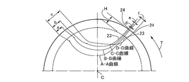
- FIG. 2 illustrates the shape of the secondary groove 26 with the tip surface of the tap 10 taken along the AA cross-sectional line, the BB cross-sectional line indicating the cross-sectional shapes of the primary groove 22 and the secondary groove 26, C- It is shown enlarged along with the C section line and the DD section line.
- the arc-shaped secondary groove follows the line indicating the linear primary groove 22. 26 is connected, and the side wall surface 23 directed in the tap rotation direction T is configured only by a curve indicating the secondary groove 26.
- connection point between the line indicating the primary groove 22 and the curve indicating the arcuate secondary groove 26 is indicated by a black dot. Since the secondary groove 26 is formed slightly longer than the length of the tip 10 of the tap 10, that is, the bite 18 in the direction of the axis C, and does not reach the DD section of FIG. It is comprised only by the line which shows the primary groove
- the tap 10 cuts an internal thread of M10 ⁇ 1.5, that is, a 10 mm diameter and a 1.5 mm pitch
- the AA cross-sectional line in FIG. , BB cross-section line, CC cross-section line, DD cross-section line, the mutual distances a, b, c in the circumferential direction are 0.7 mm, 1.0 mm, 1.6 mm, and the primary groove 22 are sequentially shifted in accordance with the lead angle ⁇ .
- the AA cross-section line, the BB cross-section line, and the CC cross-section line in FIG. 2 on the side wall surface 23 side toward the tap rotation direction T indicate the rake face of the cross section for cutting.
- the mutual distances d and e in the circumferential direction are 0.07 mm and 0.15 mm, and are substantially the same because the lead angle ⁇ of the secondary groove 26 is small.
- the DD cross section line in FIG. 2 on the side wall surface 23 side in the tap rotation direction T shows a curve of a cross section without cutting, and the AA cross section line and the DD cross section line
- the mutual interval f is 0.4 mm.
- the thread height of the complete thread portion 20 indicated by H in FIG. 2 is 0.8 mm.
- FIG. 3 is a diagram for explaining the groove bottom gradient K of the secondary groove 26.
- a predetermined section E of, for example, 1.5 mm set in the longitudinal direction of the secondary groove 26, that is, the axial center C direction of the tap 10 is set (FIG. 3A).
- the groove bottom diameter Bmm ⁇ in the cross section E1-E1 and the groove bottom diameter Amm ⁇ in the cross section E2-E2 (FIG. 3 (b)) are measured, and the groove bottom gradient K of the secondary groove 26 is calculated from the following equation (1). It is the value. Since the secondary groove 26 is formed linearly, the predetermined section E can be any value as long as it is shorter than the longitudinal dimension of the secondary groove 26, but if it is too short, the accuracy is high. Is not obtained, the above value is used.
- K tan ⁇ 1 (AB) / (2 ⁇ E) (1)
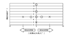
- FIG. 4 shows the result of the cutting test 1 described above, and includes a horizontal axis representing the twist angle ⁇ of the secondary groove 26 in the right and left twist directions, and a vertical axis representing the groove bottom gradient K of the secondary groove 26.
- the ⁇ marks indicate highly durable taps that can be processed with a number of tapped holes of about 20 holes or more.
- the number of processed holes is 1 or less, and the durability is not sufficiently obtained.
- the twist angle ⁇ of the secondary groove 26 is within the range of 0 to 3 ° in the right twist direction and the left twist direction, and the groove bottom gradient K of the secondary groove 26 is within the range of 5 to 15 °. was gotten.
- the cutting test when the groove bottom gradient K is 16 ° or more has not been performed, the strength is lowered and the possibility of breakage is considered.
- FIG. 5 is a two-dimensional coordinate indicating the rake angle S and the vertical axis representing the tap life (number of holes processed), showing the result of the cutting test 2 described above.
- FIG. 5 shows that the tap is highly durable and capable of processing a number of tap holes of about 80 holes or more when the rake angle S is in the range of 0 ° to ⁇ 10 °.
- the 0 ° rake angle S exceeds 0 °, it is lower than the conventional product and is 50 holes or less, and the high durability as described above cannot be obtained. Therefore, the rake angle S was high in the range of 0 ° to -10 °.
- 43HRC nickel-base heat-resistant alloy is cut with a conventional tap in which the twist angle (lead angle) ⁇ of the spiral point groove corresponding to the secondary groove 26 exceeds 5 ° as shown in the cited documents 1, 2, and 3.
- Fig. 6 (a) shows the swarf when it is made.
- Such a conventional spiral point tap has a longer life and more stable performance than a spiral tap without the secondary groove 26, but since the chips are long, durability cannot be obtained due to clogging when used in a blind hole. .
- the twist angle ⁇ of the secondary groove 26 is set in the range of 0 to 3 ° in the right-hand or left-hand direction, and the rake angle S of the cutting edge 24 is in the range of ⁇ 10 to 0 °.
- the tap 10 of the present embodiment which is set so that the groove bottom gradient K of the secondary groove 26 is in the range of 5 to 15 °, as shown in FIG. Since it was shortened, even if the pilot hole was a blind hole, high durability similar to that of a through hole was obtained.
- FIG. 7 is a chart showing the results of the cutting test 3 described above.
- the conventional tap similar to that shown in FIG. 1 except that the secondary groove 26 is not provided is broken when one hole is cut even at a relatively low cutting speed of 0.5 m / min.
- the internal thread machining within tolerance can be performed up to 25 holes at a cutting speed of 1 m / min, but accuracy beyond that (GPOUT) is exceeded, and 0.75 m / min.
- GPOUT accuracy beyond that
- female threads within tolerance can be machined up to 72 holes.
- the tap 10 of this embodiment includes the screw portion 12 in which the male screw 16 is formed, the spiral primary groove 22 formed so as to intersect the thread of the male screw 16, and the twist of the primary groove 22.
- a spiral tap having a secondary groove 26 formed at the tip of the primary groove 22 with a twist angle smaller than the angle ⁇ , the secondary groove 26 having a positive or negative twist angle ⁇ of 0 to 3 °.
- the cutting edge 24 formed on the ridge line between the side wall surface 23 facing the tap rotation direction T of the secondary groove 26 and the outer peripheral surface of the screw portion 12 has a rake angle S of ⁇ 10 to 0 °
- the secondary groove 26 has a groove bottom gradient K of 5 to 15 °.
- the tap life is greatly improved when a difficult-to-cut material such as a 45HRC nickel-base heat-resistant alloy is machined, and a highly durable tap is obtained.
- a difficult-to-cut material such as a 45HRC nickel-base heat-resistant alloy
- a highly durable tap is obtained.
- the tip strength is estimated to decrease.
- the rake angle S of the cutting edge 24 formed on the ridge line between the side wall surface 23 facing the tap rotation direction T and the outer peripheral surface of the screw portion 12 is more than ⁇ 10 °. When it is lowered (negative value is increased), the tap life is reduced, and when the rake angle S exceeds 0 °, the tap life is similarly reduced.
- the secondary groove 26 formed at the distal end portion in the primary groove 22 has a side edge on the twist direction side of the primary groove 22 of the pair of side edges of the primary groove 22.
- the side edge opposite to the twisting direction of the primary groove 22 is located on the side opposite to the twisting direction (tap rotation direction T) from the side edge on the twisting direction side.
- the side wall surface 23 on the side facing the tap rotation direction T of the secondary groove 26 functions as a rake face 23. For this reason, since the groove groove bottom is formed in the secondary groove 26 with a curve having a smaller radius of curvature than the primary groove 22, chips moving along the side wall surface (rake surface) 23 are scratched with a small diameter. , Shortened.
- the twist angle ⁇ of the secondary groove 26 is set in the range of 0 to 3 ° in the right twist direction, but is set to ⁇ 3 to 0 °. Also good. In short, as shown in FIG. 4, it may be set within the range of ⁇ 3 to 3 ° regardless of the twist direction of the primary groove 22.
- the material, the diameter, the twist angle ⁇ of the primary groove 22 and the like can be changed as appropriate.
Landscapes
- Engineering & Computer Science (AREA)
- Mechanical Engineering (AREA)
- Transmission Devices (AREA)
- Processing And Handling Of Plastics And Other Materials For Molding In General (AREA)
- Drilling Tools (AREA)
- Milling Processes (AREA)
- Gear Processing (AREA)
Description
K=tan-1(A-B)/(2×E) ・・・(1)
( 切削試験1)
・タップ:3/8-16UNC用スパイラルタップ
・切削速度:2m/min
・被削材:45HRCのニッケル基耐熱合金
・下穴径:8.1mmφ
・ねじ立て長さ:14mm
・切削液:不水溶性切削油剤
・給油方法:外部給油
( 切削試験2)
・タップ:1/4-28UNC用スパイラルタップ
・切削速度:2m/min
・被削材:45HRCのニッケル基耐熱合金
・下穴径:5.52mmφ
・ねじ立て長さ:12.7mm
・切削液:不水溶性切削油剤
・給油方法:外部給油
( 切削試験3)
・タップ:M5×0.8用スパイラルタップ
・被削材:45HRCのニッケル基耐熱合金
・下穴径:4.3mmφ
・下穴長さ:18mm(止まり)
・ねじ長さ:10.0mm(止まり)
・切削速度:0.25m/min、0.5m/min、0.75m/min、1.0m/min
・切削液:水溶性切削油剤10倍希釈
・給油方法:外部給油
・加工機:立形M/C BT30
12:ねじ部
16:雄ねじ
22:一次溝
23:側壁面(すくい面)
24:切れ刃
26:二次溝
C:軸心(回転中心)
β:二次溝のねじれ角
K:二次溝の溝底勾配
S:切れ刃のすくい角
Claims (2)
- 雄ねじが形成されたねじ部と、該雄ねじのねじ山と交差するように形成された螺旋状の一次溝と、該一次溝のねじれ角よりも小さいねじれ角で該一次溝の先端部に形成された二次溝とを備えるスパイラルタップであって、
前記二次溝は、0~3°の正または負のねじれ角を有し、
前記二次溝の一対の側壁面のうちタップ回転方向に向かう側壁面と前記ねじ部の外周面との間の稜線に形成された切れ刃は、-10~0°のすくい角を有し、
前記二次溝は、5~15°の溝底勾配を有することを特徴とするスパイラルタップ。 - 前記一次溝の先端部に形成された前記二次溝は、その一対の側縁のうち一次溝のねじれ方向側の側縁がその一次溝のねじれ方向側の側縁よりもねじれ方向とは反対側に位置し、且つねじれ方向とは反対側の側縁は、その一次溝のねじれ方向とは反対側の側縁よりも反対側に位置して、その二次溝の回転方向に向かう側の側壁面がすくい面として機能していることを特徴とする請求項1のスパイラルタップ。
Priority Applications (5)
| Application Number | Priority Date | Filing Date | Title |
|---|---|---|---|
| PCT/JP2012/056200 WO2013132665A1 (ja) | 2012-03-09 | 2012-03-09 | スパイラルタップ |
| US14/382,161 US20150016911A1 (en) | 2012-03-09 | 2012-03-09 | Spiral tap |
| CN201280071267.9A CN104159692B (zh) | 2012-03-09 | 2012-03-09 | 螺旋丝锥 |
| EP12870601.7A EP2823925B1 (en) | 2012-03-09 | 2012-03-09 | Spiral tap |
| JP2014503405A JP5756562B2 (ja) | 2012-03-09 | 2012-03-09 | スパイラルタップ |
Applications Claiming Priority (1)
| Application Number | Priority Date | Filing Date | Title |
|---|---|---|---|
| PCT/JP2012/056200 WO2013132665A1 (ja) | 2012-03-09 | 2012-03-09 | スパイラルタップ |
Publications (1)
| Publication Number | Publication Date |
|---|---|
| WO2013132665A1 true WO2013132665A1 (ja) | 2013-09-12 |
Family
ID=49116176
Family Applications (1)
| Application Number | Title | Priority Date | Filing Date |
|---|---|---|---|
| PCT/JP2012/056200 Ceased WO2013132665A1 (ja) | 2012-03-09 | 2012-03-09 | スパイラルタップ |
Country Status (5)
| Country | Link |
|---|---|
| US (1) | US20150016911A1 (ja) |
| EP (1) | EP2823925B1 (ja) |
| JP (1) | JP5756562B2 (ja) |
| CN (1) | CN104159692B (ja) |
| WO (1) | WO2013132665A1 (ja) |
Cited By (2)
| Publication number | Priority date | Publication date | Assignee | Title |
|---|---|---|---|---|
| US9839984B2 (en) | 2014-08-14 | 2017-12-12 | Kennametal Inc. | Method of making a cutting tap with a correction grind |
| WO2025186919A1 (ja) * | 2024-03-06 | 2025-09-12 | オーエスジー株式会社 | ポイントタップ |
Families Citing this family (4)
| Publication number | Priority date | Publication date | Assignee | Title |
|---|---|---|---|---|
| CN104470665A (zh) * | 2012-07-17 | 2015-03-25 | Osg株式会社 | 螺旋丝锥及其制造方法 |
| US10766083B2 (en) * | 2017-05-31 | 2020-09-08 | Kennametal Inc. | Spiral flute tap with continuously increasing helix angle |
| CN108705159A (zh) * | 2018-07-09 | 2018-10-26 | 昆山田野井量刃具设备有限公司 | 一种防崩牙丝攻 |
| AT528234A1 (de) | 2024-05-02 | 2025-11-15 | Dc Swiss S A | Werkzeug zur Materialbearbeitung |
Citations (6)
| Publication number | Priority date | Publication date | Assignee | Title |
|---|---|---|---|---|
| JPS52153198U (ja) | 1976-05-18 | 1977-11-19 | ||
| JPH01171725A (ja) | 1987-12-23 | 1989-07-06 | O S G Kk | チップカーラ付ねじれ溝タップ |
| JPH0544417U (ja) | 1991-11-25 | 1993-06-15 | オーエスジー株式会社 | ねじ切削用タツプ |
| JP2005279832A (ja) * | 2004-03-29 | 2005-10-13 | Nissan Motor Co Ltd | 直溝タップ |
| US20080069653A1 (en) * | 2006-09-19 | 2008-03-20 | Emuge-Werk Richard Glimpel Gmbh & Co. Kg Fabrik Fur Praezisionswerkzeuge | Tool for Machining a Workpiece |
| US20080075550A1 (en) * | 2006-09-22 | 2008-03-27 | Reed Gary J | Double helix thread cutting tap |
Family Cites Families (32)
| Publication number | Priority date | Publication date | Assignee | Title |
|---|---|---|---|---|
| US623614A (en) * | 1899-04-25 | Drill for tapping pipes | ||
| FR546807A (fr) * | 1922-02-04 | 1922-11-24 | Delle Soc Ind De | Tarauds perfectionnés et procédés de fabrication d'outils de filetage |
| US2033557A (en) * | 1934-01-29 | 1936-03-10 | Jesse D Tucker | Tap |
| US2202236A (en) * | 1938-04-27 | 1940-05-28 | Greenfield Tap & Die Corp | Tap |
| US2330099A (en) * | 1942-06-10 | 1943-09-21 | Frank V Whyland | Tap |
| US2557733A (en) * | 1948-04-06 | 1951-06-19 | Walter S Forcier | Self-cutting tap |
| DE1118577B (de) * | 1954-02-27 | 1961-11-30 | Helmut Glimpel Dipl Ing | Sacklochgewindebohrer mit Vor- und Nachschneidzahnleisten oder Sacklochgewindebohrersatz |
| DE1189830B (de) * | 1960-01-09 | 1965-03-25 | Glimpel Emuge Werk | Kurzspiralig genuteter Gewindebohrer |
| GB1090875A (en) * | 1964-08-16 | 1967-11-15 | Firth Brown Tools Ltd | Improvements in screw-cutting taps |
| US3458882A (en) * | 1967-03-27 | 1969-08-05 | Gerald W Kelly | Thread-cutting device |
| US4708542A (en) * | 1985-04-19 | 1987-11-24 | Greenfield Industries, Inc. | Threading tap |
| SE456408B (sv) * | 1987-02-10 | 1988-10-03 | Sandvik Ab | Borr- och gengverktyg |
| DE8803565U1 (de) * | 1988-03-16 | 1988-09-01 | Prototyp-Werke GmbH, Fabrik für Präzisionswerkzeuge, 7615 Zell | Gewindefraeser |
| DE3828780A1 (de) * | 1988-08-25 | 1990-03-01 | Schmitt M Norbert Dipl Kaufm D | Bohrgewindefraeser |
| JPH0777693B2 (ja) * | 1990-08-30 | 1995-08-23 | 出雲産業株式会社 | タップ |
| FR2701226B1 (fr) * | 1993-02-08 | 1996-11-22 | Rineau Freres Outillage Armor | Taraud a goujures helicouidales evolutives. |
| DE4319789C2 (de) * | 1993-06-15 | 1995-04-27 | Fette Wilhelm Gmbh | Gewindebohrer |
| SE505742C2 (sv) * | 1993-09-07 | 1997-10-06 | Sandvik Ab | Gängtapp |
| SE9600927D0 (sv) * | 1996-03-08 | 1996-03-08 | Sandvik Ab | Gewindeerzeugendes werkzeug |
| US5733078A (en) * | 1996-06-18 | 1998-03-31 | Osg Corporation | Drilling and threading tool |
| US5876158A (en) * | 1997-12-03 | 1999-03-02 | Beiter; Russell R. | Drive collet assembly for a tap with overdrive protection |
| SE522664C2 (sv) * | 2001-04-30 | 2004-02-24 | Sandvik Ab | Skärande gängtapp och förfarande för dess tillverkning |
| US7144208B2 (en) * | 2004-06-07 | 2006-12-05 | Kennametal Inc. | Low torque tap |
| DE102005022503B4 (de) * | 2004-09-13 | 2019-10-17 | EMUGE-Werk Richard Glimpel GmbH & Co. KG Fabrik für Präzisionswerkzeuge | Werkzeug und Verfahren zur Erzeugung eines Gewindes |
| DE102005014422B4 (de) * | 2005-03-24 | 2019-10-24 | EMUGE-Werk Richard Glimpel GmbH & Co. KG Fabrik für Präzisionswerkzeuge | Bohrgewindefräser |
| US7357606B1 (en) * | 2006-02-03 | 2008-04-15 | United States Of America As Represented By The Administrator Of The National Aeronautics And Space Administration | Self-advancing step-tap tool |
| KR100924976B1 (ko) * | 2006-11-30 | 2009-11-04 | 오에스지 가부시키가이샤 | 탭 |
| CN101400469B (zh) * | 2007-04-26 | 2014-10-22 | Osg株式会社 | 螺旋丝锥 |
| CN101549422B (zh) * | 2009-05-14 | 2011-06-15 | 沈阳飞机工业(集团)有限公司 | 加工钛合金用专用丝锥 |
| US20110076107A1 (en) * | 2009-09-25 | 2011-03-31 | Yg-1 Co., Ltd. | Tap with Dual Relief Technology |
| DE102010017163A1 (de) * | 2010-05-31 | 2011-12-01 | Gühring Ohg | Bohrwerkzeug |
| CN104470665A (zh) * | 2012-07-17 | 2015-03-25 | Osg株式会社 | 螺旋丝锥及其制造方法 |
-
2012
- 2012-03-09 JP JP2014503405A patent/JP5756562B2/ja active Active
- 2012-03-09 US US14/382,161 patent/US20150016911A1/en not_active Abandoned
- 2012-03-09 EP EP12870601.7A patent/EP2823925B1/en active Active
- 2012-03-09 WO PCT/JP2012/056200 patent/WO2013132665A1/ja not_active Ceased
- 2012-03-09 CN CN201280071267.9A patent/CN104159692B/zh active Active
Patent Citations (6)
| Publication number | Priority date | Publication date | Assignee | Title |
|---|---|---|---|---|
| JPS52153198U (ja) | 1976-05-18 | 1977-11-19 | ||
| JPH01171725A (ja) | 1987-12-23 | 1989-07-06 | O S G Kk | チップカーラ付ねじれ溝タップ |
| JPH0544417U (ja) | 1991-11-25 | 1993-06-15 | オーエスジー株式会社 | ねじ切削用タツプ |
| JP2005279832A (ja) * | 2004-03-29 | 2005-10-13 | Nissan Motor Co Ltd | 直溝タップ |
| US20080069653A1 (en) * | 2006-09-19 | 2008-03-20 | Emuge-Werk Richard Glimpel Gmbh & Co. Kg Fabrik Fur Praezisionswerkzeuge | Tool for Machining a Workpiece |
| US20080075550A1 (en) * | 2006-09-22 | 2008-03-27 | Reed Gary J | Double helix thread cutting tap |
Cited By (2)
| Publication number | Priority date | Publication date | Assignee | Title |
|---|---|---|---|---|
| US9839984B2 (en) | 2014-08-14 | 2017-12-12 | Kennametal Inc. | Method of making a cutting tap with a correction grind |
| WO2025186919A1 (ja) * | 2024-03-06 | 2025-09-12 | オーエスジー株式会社 | ポイントタップ |
Also Published As
| Publication number | Publication date |
|---|---|
| JP5756562B2 (ja) | 2015-07-29 |
| US20150016911A1 (en) | 2015-01-15 |
| CN104159692A (zh) | 2014-11-19 |
| EP2823925B1 (en) | 2017-09-13 |
| CN104159692B (zh) | 2016-07-13 |
| EP2823925A1 (en) | 2015-01-14 |
| JPWO2013132665A1 (ja) | 2015-07-30 |
| EP2823925A4 (en) | 2015-12-30 |
Similar Documents
| Publication | Publication Date | Title |
|---|---|---|
| CN101400469B (zh) | 螺旋丝锥 | |
| JP5301647B2 (ja) | ドリル付きタップ、およびめねじ加工方法 | |
| JP3834544B2 (ja) | タップ、およびその製造方法 | |
| JP5756562B2 (ja) | スパイラルタップ | |
| CN100379514C (zh) | 螺纹切削工具 | |
| US10730124B2 (en) | Taper thread-cutting spiral pipe tap | |
| JP7018136B2 (ja) | 盛上げタップ | |
| JPWO2010049989A1 (ja) | スパイラルタップ | |
| JP5301452B2 (ja) | スパイラルタップおよびその製造方法 | |
| EP3385018B1 (en) | Tapered pipe thread-machining spiral tap | |
| WO2008075402A1 (ja) | スパイラルタップ | |
| WO2018134924A1 (ja) | ねじ切りフライス | |
| JP5237659B2 (ja) | 切削タップ | |
| JP6825400B2 (ja) | テーパボールエンドミル | |
| JP2005279832A (ja) | 直溝タップ | |
| JP2025067413A (ja) | 通り穴加工用タップ | |
| CN118139711A (zh) | 丝锥 | |
| TW201713437A (zh) | 具鑽孔攻牙裝置 | |
| JP2009101452A (ja) | ドリル | |
| JPH0711228U (ja) | ねじ切削用タップ |
Legal Events
| Date | Code | Title | Description |
|---|---|---|---|
| 121 | Ep: the epo has been informed by wipo that ep was designated in this application |
Ref document number: 12870601 Country of ref document: EP Kind code of ref document: A1 |
|
| ENP | Entry into the national phase |
Ref document number: 2014503405 Country of ref document: JP Kind code of ref document: A |
|
| WWE | Wipo information: entry into national phase |
Ref document number: 14382161 Country of ref document: US |
|
| NENP | Non-entry into the national phase |
Ref country code: DE |
|
| REEP | Request for entry into the european phase |
Ref document number: 2012870601 Country of ref document: EP |
|
| WWE | Wipo information: entry into national phase |
Ref document number: 2012870601 Country of ref document: EP |