WO2013132705A1 - Véhicule ferroviaire muni d'un dispositif d'évacuation, et procédé de montage dudit dispositif d'évacuation - Google Patents
Véhicule ferroviaire muni d'un dispositif d'évacuation, et procédé de montage dudit dispositif d'évacuation Download PDFInfo
- Publication number
- WO2013132705A1 WO2013132705A1 PCT/JP2012/080452 JP2012080452W WO2013132705A1 WO 2013132705 A1 WO2013132705 A1 WO 2013132705A1 JP 2012080452 W JP2012080452 W JP 2012080452W WO 2013132705 A1 WO2013132705 A1 WO 2013132705A1
- Authority
- WO
- WIPO (PCT)
- Prior art keywords
- evacuation device
- rail vehicle
- entrance
- evacuation
- frame
- Prior art date
- Legal status (The legal status is an assumption and is not a legal conclusion. Google has not performed a legal analysis and makes no representation as to the accuracy of the status listed.)
- Ceased
Links
Images




Classifications
-
- A—HUMAN NECESSITIES
- A62—LIFE-SAVING; FIRE-FIGHTING
- A62B—DEVICES, APPARATUS OR METHODS FOR LIFE-SAVING
- A62B1/00—Devices for lowering persons from buildings or the like
- A62B1/20—Devices for lowering persons from buildings or the like by making use of sliding-ropes, sliding-poles or chutes, e.g. hoses, pipes, sliding-grooves, sliding-sheets
-
- B—PERFORMING OPERATIONS; TRANSPORTING
- B61—RAILWAYS
- B61B—RAILWAY SYSTEMS; EQUIPMENT THEREFOR NOT OTHERWISE PROVIDED FOR
- B61B13/00—Other railway systems
- B61B13/04—Monorail systems
- B61B13/06—Saddle or like balanced type
-
- B—PERFORMING OPERATIONS; TRANSPORTING
- B61—RAILWAYS
- B61D—BODY DETAILS OR KINDS OF RAILWAY VEHICLES
- B61D19/00—Door arrangements specially adapted for rail vehicles
- B61D19/02—Door arrangements specially adapted for rail vehicles for carriages
- B61D19/023—Emergency exits
-
- B—PERFORMING OPERATIONS; TRANSPORTING
- B61—RAILWAYS
- B61K—AUXILIARY EQUIPMENT SPECIALLY ADAPTED FOR RAILWAYS, NOT OTHERWISE PROVIDED FOR
- B61K13/00—Other auxiliaries or accessories for railways
- B61K13/04—Passenger-warning devices attached to vehicles; Safety devices for preventing accidents to passengers when entering or leaving vehicles
Definitions
- the present invention relates to an evacuation device provided in a rail vehicle that travels along a track installed on an overpass, and a rail vehicle including the evacuation device, and particularly guides an evacuee near the evacuation device.
- the present invention relates to an evacuation device capable of enhancing safety during evacuation of an evacuation guide and an evacuee, a rail vehicle provided with the evacuation device, and a method of fixing the evacuation device to the rail vehicle.
- an evacuation guide When evacuating from the rail vehicle to the ground, first, a crew member or the like (hereinafter referred to as an evacuation guide) who rides on the rail vehicle pulls out the evacuation device from the storage location and installs it at the entrance / exit where the side sliding door is opened. Thereafter, the evacuation guide guides the passenger to the evacuation device and evacuates to the ground using the escape shooter built in the evacuation device.
- the evacuation guide guides the refugee to the entrance of the evacuation device (an escape shooter with a spiral slide inside the cylinder) near the evacuation device installed in the opened side sliding door and escapes. It must be monitored that the number of evacuees descending on the shooter does not exceed the escape shooter capacity. For this reason, it is desirable that the state of the refugee evacuating from the exit of the escape shooter to be seen from the rail vehicle, and there is a problem to be improved in terms of further improving the safety of the refugee and the evacuation guide.
- An object of the present invention is an evacuation device provided in a rail vehicle that is operated along a rail laid on an overpass, and the evacuation device can be selectively installed on a side sliding door, and the side sliding door of the rail vehicle It is another object of the present invention to provide an evacuation device that can be fixed with a simple configuration and procedure and that can be used more safely by refugees and evacuation guides.
- a rail vehicle includes an evacuation device installed at an entrance / exit, and the evacuation device is an escape shooter that forms an escape route, and the entrance / exit from above the evacuation device. It has the shielding object which covers the range which reaches the upper part of this.
- the evacuation device is provided at the entrance / exit of the rail vehicle, and is provided with a fall prevention plate provided so as to be rotatable around the vertical shafts disposed on the left and right frame portions of the main body frame, and the main body frame.
- a holding frame rotatably provided around a horizontal axis disposed at a lower end of the evacuation unit, and an escape shooter provided in the holding frame, and further from the upper part of the evacuation device to the upper part of the entrance / exit It is characterized by including a shield covering the entire range.
- the evacuation device can be selectively installed on the side sliding door, and the evacuation device can be fixed to the side sliding door of the rail vehicle with a simple configuration and procedure. Can be provided.
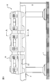
- FIG. 1 is a side view schematically showing a monorail vehicle (rail vehicle) that travels on an elevated track to which an evacuation device according to the present invention is applied.
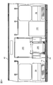
- 2 is a cross-sectional view taken along the line AA of the monorail vehicle shown in FIG. 3 is a BB cross-sectional view of the monorail vehicle shown in FIG.
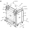
- FIG. 4 is a perspective view of the evacuation device according to the present invention as seen from the inside of the monorail vehicle to the outside of the vehicle.
- FIG. 5 is a perspective view of the evacuation device according to the present invention as seen from the outside of the monorail vehicle to the inside of the vehicle.
- FIG. 1 is a side view schematically showing a monorail vehicle (rail vehicle) that travels on an elevated track to which an evacuation device according to the present invention is applied.
- 2 is a cross-sectional view taken along the line AA of the monorail vehicle shown in FIG. 3 is a BB cross-sectional view of the monorail vehicle shown in FIG.
- FIG. 4 is a
- FIG. 6 is a diagram showing a use situation of the evacuation device according to the present invention, and is a perspective view of the evacuation device in the use situation as seen from the inside of the monorail vehicle to the outside of the vehicle.
- FIG. 7 is a perspective view illustrating a developed state of the holding frame including the tread included in the evacuation device illustrated in FIG. 6.
- FIG. 8 is a top view showing a state in which the evacuation device according to the present invention is fixed to the side sliding door of the monorail vehicle.
- FIG. 9 is a cross-sectional view taken along the line CC when the evacuation device shown in FIG. 8 is fixed to a monorail vehicle.
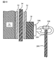
- FIG. 10 is an enlarged cross-sectional view taken along the line EE for showing the fixed position of the evacuation device shown in FIG.
- FIG. 11 is a view of the evacuation device fixed to the monorail vehicle as viewed from the inside of the vehicle.
- FIG. 1 is a side view of a straddle-type monorail vehicle 10 (hereinafter referred to as “monorail vehicle 10”) as an example of a rail vehicle.
- a rail vehicle is a vehicle that travels while being guided by a laid track, such as a railway vehicle, a straddle type (suspension type) monorail vehicle, a vehicle for a new transportation system, and the like.
- a straddle-type monorail vehicle is provided as an example of a rail vehicle, and is operated along a rail (track) laid on an overpass and provided with an evacuation device provided at an entrance / exit. 10, the evacuation device 200 provided in the straddle-type monorail vehicle 10 and a method of fixing the evacuation device 200 to the entrance / exit of the straddle-type monorail vehicle 10 will be described.
- a monorail vehicle 10 shown in FIG. 1 is composed of three vehicles connected to each other, and travels on a track girder 2 that is laid from the ground 1 to a height H.
- the monorail vehicle 10 is supported along a track girder 2 by being supported by a carriage (not shown) including a support wheel that rolls on the upper surface of the track girder 2 and guide wheels and stabilizer wheels that roll on both side surfaces of the track girder. Run.
- An air conditioner 45 is provided on the roof of the monorail vehicle 10 to adjust the temperature and humidity in the vehicle.
- the bogie that supports the monorail vehicle 10 and various devices provided under the floor of the monorail vehicle 10 are covered with a skirt 22 that is provided in a form continuous with the side structure 30 described later, and suppresses the propagation of noise generated from these devices. is doing.
- FIG. 2 is a cross-sectional view of the monorail vehicle 10 shown in FIG.
- the monorail vehicle 10 includes side structures 30 and 30 at both ends in the width direction of the underframe 20, and includes wife structures (not shown) at both ends in the longitudinal direction, and the upper ends of the side structures 30 and 30 and the wife structure. It is comprised by mounting the roof structure 40 in the.
- the underside of the underframe 20 is provided with an underfloor equipment room in which underfloor equipment (not shown) such as a main converter, a transformer, and an auxiliary power supply is mounted.
- a floor 14 is formed on the upper surface of the underframe 20.
- On the floor 14, a storage room 100 for storing an evacuation device 200 (to be described later), a chair 39, and a side sliding door that opens and closes an entrance for passengers to get on and off. 34, etc. are provided.
- FIG. 3 is a BB cross-sectional view of the monorail vehicle shown in FIG. Only one width direction 270 side where the evacuation device 200 is disposed from the center line 16 along the longitudinal direction of the monorail vehicle body 10 is shown.
- the side structure 30 constituting the monorail vehicle 10 is provided with door pockets 32 and 32 for storing side sliding doors 34 and 34 that are opened and closed when passengers get on and off, and corresponds to the lower end portion of the side sliding door 34.
- a step 24 is provided on the side surface of the underside of the underframe 20 along the opening and closing direction.
- a storage room 100 in which the evacuation device 200 is stored is provided on the side of the one side sliding door 34.
- the storage chamber 100 has a rectangular parallelepiped box shape, and includes a door 120 having a substantially L-shaped cross section in the vertical direction. The door 120 is rotated around the rotation shaft 110 provided at one vertical edge of the door 120, and the evacuation device 200 is taken in and out of the storage chamber 100.
- the other vertical edge of the door 120 is closed by a seal or the like that can be easily broken. In an emergency, after the seal is broken, the door 120 can be opened and the evacuation device 200 can be quickly taken out from the storage chamber 100. In addition, the generation of noise from the door 120 due to vibration during traveling of the monorail vehicle 10 is suppressed.
- a handrail 38 is provided on the side of the other side sliding door 34, and a chair 39 is provided on the floor 14 along the longitudinal direction of the monorail vehicle 10.
- FIG. 4 is a perspective view of the evacuation device according to the present invention as seen from the inside of the monorail vehicle to the outside of the vehicle.
- FIG. 5 is a perspective view of the evacuation device according to the present invention as seen from the outside of the monorail vehicle to the inside of the vehicle.
- the evacuation device 200 is a rectangular parallelepiped main body frame 210 composed of vertical members 212 and cross members 214, and both ends of the main body frame 210 in the longitudinal direction (vehicle body longitudinal direction indicated by an arrow 272).
- a holding frame 240 (see FIG. 5) having fall prevention plates 230, 230 provided along the edge and an escape shooter 260 having a spiral slide on which passengers slide down, and a tread 242 (see FIG. 7) forming an escape route.
- Reference a tread 222 (see FIG. 6) provided on the lower surface of the main body frame 210, and a shield 280 provided on the upper portion of the main body frame 210.
- the shield 280 closes the space from the upper end of the evacuation device 200 to the upper part of the entrance when the evacuation device 200 is fixed to the entrance / exit of the monorail vehicle 10 (open side sliding door 34). It is provided in the upper part of the main body frame 210 in the state where it was attached.
- the main body frame 210 has a rectangular parallelepiped shape in which a frame in which a vertical member 212 and a horizontal member 214 are combined and a frame are arranged to face each other and the frame and the frame are connected by the horizontal member 214.
- a folded escape shooter 260 is housed inside the main body frame 210.
- the fall prevention plates 230 and 230 are attached such that one of the vertical edges of the fall prevention plates 230 and 230 is rotatable around a rotation shaft 234 along the vertical member 212 forming the frame, and the evacuation device 200 is provided on the other vertical edge.
- abutting portion 236 that abuts on the door pocket pillar 36 when being provided on the door 34, and an engaging portion 232 that engages the evacuation device 200 on the door pocket pillar 36 in a manner connected to the abutting portion 236.
- a rubber plate is affixed to the abutting portion 236 for cushioning when the evacuation device 200 abuts against the door pocket pillar 36.
- the locking portion 232 has a function of suppressing movement of the evacuation device 200 in the direction of the arrow 272 (longitudinal direction of the monorail vehicle).
- the contact portion 236 does not necessarily have to be in contact with the door pocket column 36, and the vehicle width direction 270 of the evacuation device 200 is not necessarily required. What is necessary is just to contact
- the holding frame 240 that holds the escape shooter 260 is rotatably provided around a rotation shaft 244 provided at the lower end portion of the main body frame 210, and is stored in the main body frame 210 in an upright state when stored.
- a wheel 224 is provided below the cross member 214 constituting the lower surface of the main body frame 210, and the evacuation device 200 taken out from the storage 100 can be easily transported to an arbitrary side sliding door 34. Since the wheel 224 is fixed to the cross member 214 via a joint rotatable in a horizontal plane, the moving direction can be easily changed.
- FIG. 6 is a diagram showing a use situation of the evacuation device according to the present invention, and is a perspective view of the evacuation device in the use situation as seen from the inside of the monorail vehicle to the outside of the vehicle.
- illustration of the monorail vehicle 10 is abbreviate
- the evacuation device 200 taken out of the storage room 100 is transported to the vicinity of the side sliding doors 34 and 34 corresponding to the point where it is confirmed that the evacuation can be safely performed, and the side sliding doors 34 and 34 are manually opened, and then described later. Through this procedure, the door is fixed to the inside of the entrance / exit (open side doors 34, 34).
- the surfaces of the fall prevention plates 230 and 230 provided at both ends of the evacuation device 200 are deployed until they are substantially parallel to the side structure 30 (not shown) of the monorail vehicle 10.
- the fall prevention stoppers 231 and 231 provided therein are developed until they are substantially horizontal, and the deployment state of the fall prevention plates 230 and 230 is reached. Hold.
- the drop-preventing stopper 231 has a substantially right-angled triangle shape when viewed from above, and a member corresponding to one side forming a right angle of the right-angle triangle extends along the longitudinal direction of the cross member 214 forming the main body frame 210.
- the main body frame 210 is rotatably provided.
- the fall prevention stopper 231 provided so as to be rotatable is developed to a substantially horizontal height, and the inside surface of the fall prevention plate 230 is supported to support the fall prevention plate 230.
- the expanded state of is maintained.
- the holding frame 240 including the escape shooter 260 and the tread plate 242 is deployed to the outside of the vehicle, and the escape shooter 260 that has been folded and stored is deployed to the ground 1.
- the holding frame 240 has wire anchoring portions 248 and 248 (see FIG. 7) provided at the front end portion thereof and a wire anchoring portion provided at an upper portion of the main body frame 210 so that the deployed holding frame 240 can be maintained substantially horizontal. 218 and 218 are connected by wires 250 and 250.
- the shielding object 280 provided in a state of being folded on the upper part of the main body frame 210 is developed, and the upper fixing portions 284 and 284 of the shielding object 280 are provided on the upper part of the entrance / exit, and the locking part 286 (FIG. 9) and the operation of fixing the evacuation device 200 to a predetermined entrance is completed. Since the lower fixing part 282 (see FIG. 9) of the shield 280 is connected to the upper end of the main body frame 210, the shield 280 can shield the space from the upper part of the evacuation device 200 to the upper part of the entrance / exit. it can.
- the material of the shield 280 may be a window or a sheet partially provided with a transparent material, a net, a sheet folded in a bellows shape, etc. so that the evacuation guide can visually check the status of the refugee. good. Further, the shield 280 has such a strength that it will not break even when an evacuee leans on it.
- the fall prevention plates 230, 230 prevent the passenger from falling by closing the gap between the side sliding door 34 of the monorail vehicle 10 and the evacuation device 200, and the tread 222 provided at the lower part of the main body frame 210, and the deployed holding frame
- the tread 242 provided in 240 constitutes a continuous evacuation path that reaches the entrance of the escape shooter 260.
- the evacuees can easily reach the entrance of the extended escape shooter 260 from the inside of the monorail vehicle 10 via the treads 222 and 242, and thus can evacuate smoothly. Furthermore, since the shield 280 closes the open space between the upper part of the evacuation device 200 and the upper part of the entrance / exit, the safety of the evacuation guide and the refugee can be further improved. Furthermore, since the evacuation guide can see the state of the refugee through the shield 280 having the permeable part, the evacuation situation can be easily grasped. Therefore, since it is possible to suppress the escape shooter 260 from guiding more evacuees than the capacity at one time, safety can be improved.
- the fall prevention plate 230 may be formed of an extruded shape that is extruded along the vertical direction, or a structure in which a thin plate is attached as a skin member to a frame that is a bone member in order to reduce weight. There may be.
- the shielding object 280 does not necessarily need to be equipped with the evacuation apparatus 200, and it is separate from the evacuation apparatus 200 to the storage chamber 100.
- the space from the upper part of the evacuation device 200 to the upper part of the entrance / exit may be closed with a separate shield 280, or
- the shield 280 is provided in a folded state at the upper part (the upper part inside the vehicle of the side structure 30), and after the evacuation device 200 is fixed to the entrance / exit, the shield 280 is extended from the upper part of the entrance / exit.
- the space from the upper part of the entrance / exit to the upper part of the evacuation device 200 may be closed by connecting to the upper part of 200.
- FIG. 7 is a perspective view illustrating a developed state of the holding frame including the tread included in the evacuation device illustrated in FIG. 6.
- the holding frame 240 is formed of a rectangular frame, and a cylinder 243 on one side forming the frame is provided to be rotatable around a rotation shaft 234 at the bottom of the main body frame 210.
- Another cylindrical body 244 is provided on the holding frame 240 in a form along the axis of the cylindrical body 243 forming the holding frame 240.
- the cylindrical body 244 is provided with an abutting portion 246 that abuts on a step 24 (see FIG. 3) provided at a lower portion of the entrance when the holding frame 210 is expanded to the outside of the vehicle at the time of evacuation.
- the abutting portion 246 is a member made of a plate material, and has an L-shaped vertical cross-sectional shape so that it can abut on the step 24 on two sides.
- a tread 242 is provided in such a manner as to straddle the cylindrical body 243 and the cylindrical body 244, and constitutes a part of the route where the evacuees reach the entrance of the escape shooter 260.
- a canvas holding frame 292 that supports a canvas (not shown) that covers a range from the tread 242 provided in the holding frame 240 to the entrance of the escape shooter 260 from the inside, and serves as a handrail when the passenger slides into the entrance of the escape shooter 260. Is provided in such a manner that it can be rotated around the rotation axis 234 of the cylindrical body 243.
- the campus holding frame 292 includes a mechanism (not shown) that can maintain the angle ⁇ with respect to the holding frame 240.
- the cylinder 245 which is one side of the holding frame 240 and is most distant from the cylinder 243 that is rotatably connected to the main body frame 210 is tethered to the belts 250 and 250 supporting the canvas described above. Portions 249 and 249 are provided.
- FIG. 8 is a top view (corresponding to FIG. 3) showing a state where the evacuation device according to the present invention is fixed to the side sliding door of the monorail vehicle.
- the evacuation device 200 is pulled out from the hangar 100 to the vicinity of the selected side sliding doors 34 and 34.
- the side sliding doors 34, 34 are opened by handling a door cock or the like that can be manually opened and closed.
- the contact portions 236, 236 of the fall prevention plates 230, 230 are moved to the door pocket. It is made to contact
- the locking portions 232 and 232 continuously provided in the contact portions 236 and 236 lock the door column pillars 36 and 36 to suppress the movement of the evacuation device 200 in the longitudinal direction of the monorail vehicle 10.
- the abutting portion 236 can increase the shock when the fall prevention plate 230 is brought into contact with the door column 36 and the frictional force in the longitudinal direction of the monorail vehicle 10 between the fall prevention plate 230 and the surface of the door column 36. Rubber etc. are provided.
- the fall prevention plate 230 has a safety function for preventing the passenger from escaping from the gap between the evacuation device 200 and the opened side sliding door 36 and a function for fixing the evacuation device 200 to the monorail vehicle 10 when the passenger evacuates. Have both. Since the dimension along the monorail vehicle body 10 when the fall prevention plates 230, 230 of the evacuation device 200 are deployed is set slightly larger than the dimension of the opened side sliding doors 34, 34, the evacuation device 200 is separated from the monorail vehicle 10 on the ground. Can be prevented from falling to.
- the tread 242 is provided in such a manner that it projects outward from the side structure 30 in the width direction (direction of arrow 270) of the monorail vehicle 10, and the escape shooter 260 is located outside the tread 242 (in the direction away from the monorail vehicle 10).
- the escape shooter 260 deployed from the holding frame 240 toward the ground 1 is installed at a position away from the skirt 22 of the monorail vehicle 10, and the escape shooter 260 may contact the monorail vehicle 10. Since it is suppressed, the safety of evacuees can be increased.
- FIG. 9 is a cross-sectional view taken along the line CC when the evacuation device shown in FIG. 8 is fixed to a monorail vehicle.
- the holding frame 240 provided in the evacuation device 200 is expanded in the direction of pushing from the vehicle inner side to the vehicle outer side, the mooring portions 218 and 218 provided at the upper end portion of the main body frame 210 and the wire mooring portion 248 provided in the holding frame 240. 248 is connected by the wires 250 and 250, so that the holding frame 240 including the tread 242 is maintained substantially horizontal.
- the escape shooter 260 folded and stored in the main body frame 210 is extended in the process of descending, and an evacuation path from the tread board 222 through the tread board 242 to the escape shooter 260 is formed.
- the shielding object 280 provided in a state of being folded on the upper part of the main body frame 210 of the evacuation device 200 is developed, and the upper fixing portions 284 and 284 of the shielding object 280 are provided at the upper part of the entrance / exit. As a result, the operation of fixing the series of evacuation devices 200 to a predetermined entrance / exit is completed.
- the evacuation device 200 Since the lower fixing portion 282 (see FIG. 9) of the shield 280 is connected to the upper end portion of the main body frame 210, the evacuation device 200 is provided by the shield 280 made of a sheet or a net having a partially transparent portion. The space from the top of the door to the top of the entrance is blocked. In other words, since the height dimension h1 of the evacuation device 200 is smaller than the height dimension h2 of the entrance / exit, the open range from the upper part of the evacuation apparatus 200 to the upper part of the entrance / exit is covered with the shield 280 and closed. Yes.
- the belt anchoring portions 249 and 249 at the upper end portion of the main body frame 210 and the belt anchoring portions 249 and 249 provided in the cylindrical body 245 forming the holding frame 240 are connected by belts 254 and 254 via the canvas support frame 292.
- the belts 254 and 254 and the canvas support frame 292 support a canvas (not shown) that covers the escape path from the tread 242 to the entrance of the escape shooter 260 from the inside.
- the canvas prevents the evacuees from recognizing the height, they can reduce the fear of the evacuees and promote prompt evacuation. Further, since the holding frame 240 is maintained substantially horizontal, the evacuees go through the tread board 222 provided at the lower part of the main body frame 210 continuously arranged from the floor 14 and the tread board 242 provided in the holding frame 240. Since the evacuation route to the entrance of the escape shooter 260 can be easily advanced, the evacuation can be promptly performed. Moreover, since the shield 280 blocks the open space between the upper part of the evacuation device 200 and the upper part of the entrance / exit, the safety of the evacuation guide and the refugee can be further improved. Furthermore, since the shield 280 has a part where the state of the refugee can be seen, the evacuation guider can easily grasp the evacuation situation and can suppress guiding more refugees than the capacity of the escape shooter 260 at one time. .
- FIG. 10 is an enlarged cross-sectional view of EE for showing the fixing position of the evacuation device shown in FIG. 9, and shows the connection structure between the upper part of the entrance / exit of the monorail vehicle 10 and the upper fixing part 284 of the shield 280.
- a mooring portion 286 having a ring-shaped portion is provided on the upper portion of the door column pillar 36 in the vicinity of the entrance / exit, and the mooring portion 286 and the upper fixing portion 284 of the shield 280 are connected by a fastener 288.
- the mooring portion 286 may be provided not in the side structure 30 but in the interior material or the door pocket 32 or the door pocket pillar 36 provided in the side structure 30 and having an appropriate strength.
- FIG. 11 is a view of the evacuation device fixed to the monorail vehicle as viewed from the inside of the vehicle.
- a state in which the range from the upper part of the evacuation device 200 that is fixed to the entrance / exit by unfolding the fall prevention plates 230, 230 to the upper part of the entrance / exit that opens the side sliding doors 34, 34 is covered by the shielding object 280. Is shown.
- the safety of the evacuation guide and the refugee can be further increased.
- the evacuation guide can visually check the state of the refugee through the shield 280, the evacuation state can be easily grasped, and it is possible to suppress guiding more refugees than the capacity of the escape shooter 260 at one time.
Landscapes
- Engineering & Computer Science (AREA)
- Mechanical Engineering (AREA)
- Business, Economics & Management (AREA)
- Emergency Management (AREA)
- Health & Medical Sciences (AREA)
- General Health & Medical Sciences (AREA)
- Transportation (AREA)
- Emergency Lowering Means (AREA)
Priority Applications (1)
| Application Number | Priority Date | Filing Date | Title |
|---|---|---|---|
| IN7371DEN2014 IN2014DN07371A (fr) | 2012-03-09 | 2012-11-26 |
Applications Claiming Priority (2)
| Application Number | Priority Date | Filing Date | Title |
|---|---|---|---|
| JP2012-052751 | 2012-03-09 | ||
| JP2012052751A JP5793097B2 (ja) | 2012-03-09 | 2012-03-09 | 避難装置を備える軌条車両および避難装置の固定方法 |
Publications (1)
| Publication Number | Publication Date |
|---|---|
| WO2013132705A1 true WO2013132705A1 (fr) | 2013-09-12 |
Family
ID=49116204
Family Applications (1)
| Application Number | Title | Priority Date | Filing Date |
|---|---|---|---|
| PCT/JP2012/080452 Ceased WO2013132705A1 (fr) | 2012-03-09 | 2012-11-26 | Véhicule ferroviaire muni d'un dispositif d'évacuation, et procédé de montage dudit dispositif d'évacuation |
Country Status (3)
| Country | Link |
|---|---|
| JP (1) | JP5793097B2 (fr) |
| IN (1) | IN2014DN07371A (fr) |
| WO (1) | WO2013132705A1 (fr) |
Cited By (1)
| Publication number | Priority date | Publication date | Assignee | Title |
|---|---|---|---|---|
| FR3107687A1 (fr) * | 2020-03-02 | 2021-09-03 | Alstom Transport Technologies | Ensemble d’évacuation pour véhicule ferroviaire |
Citations (5)
| Publication number | Priority date | Publication date | Assignee | Title |
|---|---|---|---|---|
| JPS442958Y1 (fr) * | 1966-10-11 | 1969-02-03 | ||
| JPS5742844U (fr) * | 1980-08-22 | 1982-03-09 | ||
| JPH03755U (fr) * | 1989-05-24 | 1991-01-08 | ||
| JP2003523243A (ja) * | 2000-02-21 | 2003-08-05 | エーイーエス 2000 リミテッド | 多層階ビルディング用の救助システム |
| JP2011131795A (ja) * | 2009-12-25 | 2011-07-07 | Hitachi Ltd | 軌条車両に備えられる避難装置及びその避難装置の軌条車両への固定方法 |
-
2012
- 2012-03-09 JP JP2012052751A patent/JP5793097B2/ja active Active
- 2012-11-26 WO PCT/JP2012/080452 patent/WO2013132705A1/fr not_active Ceased
- 2012-11-26 IN IN7371DEN2014 patent/IN2014DN07371A/en unknown
Patent Citations (5)
| Publication number | Priority date | Publication date | Assignee | Title |
|---|---|---|---|---|
| JPS442958Y1 (fr) * | 1966-10-11 | 1969-02-03 | ||
| JPS5742844U (fr) * | 1980-08-22 | 1982-03-09 | ||
| JPH03755U (fr) * | 1989-05-24 | 1991-01-08 | ||
| JP2003523243A (ja) * | 2000-02-21 | 2003-08-05 | エーイーエス 2000 リミテッド | 多層階ビルディング用の救助システム |
| JP2011131795A (ja) * | 2009-12-25 | 2011-07-07 | Hitachi Ltd | 軌条車両に備えられる避難装置及びその避難装置の軌条車両への固定方法 |
Cited By (2)
| Publication number | Priority date | Publication date | Assignee | Title |
|---|---|---|---|---|
| FR3107687A1 (fr) * | 2020-03-02 | 2021-09-03 | Alstom Transport Technologies | Ensemble d’évacuation pour véhicule ferroviaire |
| EP3875336A1 (fr) * | 2020-03-02 | 2021-09-08 | ALSTOM Transport Technologies | Ensemble d'évacuation pour véhicule ferroviaire |
Also Published As
| Publication number | Publication date |
|---|---|
| IN2014DN07371A (fr) | 2015-04-24 |
| JP2013184629A (ja) | 2013-09-19 |
| JP5793097B2 (ja) | 2015-10-14 |
Similar Documents
| Publication | Publication Date | Title |
|---|---|---|
| JP5237930B2 (ja) | 軌条車両に備えられる避難装置及びその避難装置の軌条車両への固定方法 | |
| CN101954914B (zh) | 一种用于磁浮轨道交通的快速安全疏散系统及其实施方法 | |
| JP5680745B2 (ja) | ホームドア装置 | |
| KR101829867B1 (ko) | 고층 건물용 화재 대피 장치 | |
| WO2021028096A1 (fr) | Appareil de sécurité pour cabine d'ascenseur se déplaçant dans une direction horizontale | |
| KR101702624B1 (ko) | 복합수송객차 | |
| JP5793097B2 (ja) | 避難装置を備える軌条車両および避難装置の固定方法 | |
| KR101374540B1 (ko) | 고가 사다리차 | |
| KR101309769B1 (ko) | 철도 차량용 가동 발판 장치 | |
| JP5793124B2 (ja) | 軌条車両に備えられる避難装置 | |
| JP5150438B2 (ja) | 鉄道車両用避難梯子装置 | |
| JP2015182522A (ja) | 避難用梯子 | |
| JP2567285B2 (ja) | 車両輸送用貨車 | |
| KR200357539Y1 (ko) | 지하철 비상대피용 통로 | |
| RU2709290C1 (ru) | Способ эвакуации пассажиров с ограниченными возможностями в ходьбе из тоннеля метрополитена и устройство для его осуществления | |
| KR20170133052A (ko) | 침상 환자 화재 대피용 이송낭 피난장치 | |
| JP6340050B2 (ja) | マシンルームレスエレベータ用制御盤システム | |
| JP2018086992A (ja) | 昇降装置付き乗物 | |
| JP2005161972A (ja) | 車両用ステップ装置 | |
| JP6975825B2 (ja) | 乗降装置およびそれを備える鉄道車両 | |
| JP6630795B1 (ja) | 非常梯子の載置台および鉄道車両 | |
| EP2784017B1 (fr) | Ascenseur pour une tour de turbine éolienne | |
| JP2018094957A (ja) | 乗降システム | |
| JP2012210896A (ja) | プラットホームゲート装置 | |
| JP6817672B2 (ja) | プラットホーム用ゲート装置 |
Legal Events
| Date | Code | Title | Description |
|---|---|---|---|
| 121 | Ep: the epo has been informed by wipo that ep was designated in this application |
Ref document number: 12870864 Country of ref document: EP Kind code of ref document: A1 |
|
| NENP | Non-entry into the national phase |
Ref country code: DE |
|
| 122 | Ep: pct application non-entry in european phase |
Ref document number: 12870864 Country of ref document: EP Kind code of ref document: A1 |