WO2013133140A1 - ソリッドワイヤおよびこれを用いたガスシールドアーク溶接方法 - Google Patents
ソリッドワイヤおよびこれを用いたガスシールドアーク溶接方法 Download PDFInfo
- Publication number
- WO2013133140A1 WO2013133140A1 PCT/JP2013/055567 JP2013055567W WO2013133140A1 WO 2013133140 A1 WO2013133140 A1 WO 2013133140A1 JP 2013055567 W JP2013055567 W JP 2013055567W WO 2013133140 A1 WO2013133140 A1 WO 2013133140A1
- Authority
- WO
- WIPO (PCT)
- Prior art keywords
- gas
- period
- mass
- solid wire
- welding
- Prior art date
- Legal status (The legal status is an assumption and is not a legal conclusion. Google has not performed a legal analysis and makes no representation as to the accuracy of the status listed.)
- Ceased
Links
Images


Classifications
-
- B—PERFORMING OPERATIONS; TRANSPORTING
- B23—MACHINE TOOLS; METAL-WORKING NOT OTHERWISE PROVIDED FOR
- B23K—SOLDERING OR UNSOLDERING; WELDING; CLADDING OR PLATING BY SOLDERING OR WELDING; CUTTING BY APPLYING HEAT LOCALLY, e.g. FLAME CUTTING; WORKING BY LASER BEAM
- B23K35/00—Rods, electrodes, materials, or media, for use in soldering, welding, or cutting
- B23K35/02—Rods, electrodes, materials, or media, for use in soldering, welding, or cutting characterised by mechanical features, e.g. shape
- B23K35/0255—Rods, electrodes, materials, or media, for use in soldering, welding, or cutting characterised by mechanical features, e.g. shape for use in welding
- B23K35/0261—Rods, electrodes or wires
-
- B—PERFORMING OPERATIONS; TRANSPORTING
- B23—MACHINE TOOLS; METAL-WORKING NOT OTHERWISE PROVIDED FOR
- B23K—SOLDERING OR UNSOLDERING; WELDING; CLADDING OR PLATING BY SOLDERING OR WELDING; CUTTING BY APPLYING HEAT LOCALLY, e.g. FLAME CUTTING; WORKING BY LASER BEAM
- B23K35/00—Rods, electrodes, materials, or media, for use in soldering, welding, or cutting
- B23K35/22—Rods, electrodes, materials, or media, for use in soldering, welding, or cutting characterised by the composition or nature of the material
- B23K35/24—Selection of soldering or welding materials proper
- B23K35/30—Selection of soldering or welding materials proper with the principal constituent melting at less than 1550°C
- B23K35/3053—Fe as the principal constituent
-
- B—PERFORMING OPERATIONS; TRANSPORTING
- B23—MACHINE TOOLS; METAL-WORKING NOT OTHERWISE PROVIDED FOR
- B23K—SOLDERING OR UNSOLDERING; WELDING; CLADDING OR PLATING BY SOLDERING OR WELDING; CUTTING BY APPLYING HEAT LOCALLY, e.g. FLAME CUTTING; WORKING BY LASER BEAM
- B23K9/00—Arc welding or cutting
- B23K9/02—Seam welding; Backing means; Inserts
- B23K9/025—Seam welding; Backing means; Inserts for rectilinear seams
-
- B—PERFORMING OPERATIONS; TRANSPORTING
- B23—MACHINE TOOLS; METAL-WORKING NOT OTHERWISE PROVIDED FOR
- B23K—SOLDERING OR UNSOLDERING; WELDING; CLADDING OR PLATING BY SOLDERING OR WELDING; CUTTING BY APPLYING HEAT LOCALLY, e.g. FLAME CUTTING; WORKING BY LASER BEAM
- B23K9/00—Arc welding or cutting
- B23K9/09—Arrangements or circuits for arc welding with pulsed current or voltage
- B23K9/091—Arrangements or circuits for arc welding with pulsed current or voltage characterised by the circuits
- B23K9/093—Arrangements or circuits for arc welding with pulsed current or voltage characterised by the circuits the frequency of the pulses produced being modulable
-
- B—PERFORMING OPERATIONS; TRANSPORTING
- B23—MACHINE TOOLS; METAL-WORKING NOT OTHERWISE PROVIDED FOR
- B23K—SOLDERING OR UNSOLDERING; WELDING; CLADDING OR PLATING BY SOLDERING OR WELDING; CUTTING BY APPLYING HEAT LOCALLY, e.g. FLAME CUTTING; WORKING BY LASER BEAM
- B23K9/00—Arc welding or cutting
- B23K9/16—Arc welding or cutting making use of shielding gas
- B23K9/173—Arc welding or cutting making use of shielding gas and of a consumable electrode
-
- B—PERFORMING OPERATIONS; TRANSPORTING
- B23—MACHINE TOOLS; METAL-WORKING NOT OTHERWISE PROVIDED FOR
- B23K—SOLDERING OR UNSOLDERING; WELDING; CLADDING OR PLATING BY SOLDERING OR WELDING; CUTTING BY APPLYING HEAT LOCALLY, e.g. FLAME CUTTING; WORKING BY LASER BEAM
- B23K9/00—Arc welding or cutting
- B23K9/23—Arc welding or cutting taking account of the properties of the materials to be welded
-
- B—PERFORMING OPERATIONS; TRANSPORTING
- B23—MACHINE TOOLS; METAL-WORKING NOT OTHERWISE PROVIDED FOR
- B23K—SOLDERING OR UNSOLDERING; WELDING; CLADDING OR PLATING BY SOLDERING OR WELDING; CUTTING BY APPLYING HEAT LOCALLY, e.g. FLAME CUTTING; WORKING BY LASER BEAM
- B23K2101/00—Articles made by soldering, welding or cutting
- B23K2101/006—Vehicles
-
- B—PERFORMING OPERATIONS; TRANSPORTING
- B23—MACHINE TOOLS; METAL-WORKING NOT OTHERWISE PROVIDED FOR
- B23K—SOLDERING OR UNSOLDERING; WELDING; CLADDING OR PLATING BY SOLDERING OR WELDING; CUTTING BY APPLYING HEAT LOCALLY, e.g. FLAME CUTTING; WORKING BY LASER BEAM
- B23K2101/00—Articles made by soldering, welding or cutting
- B23K2101/34—Coated articles ; Surface treated articles
-
- B—PERFORMING OPERATIONS; TRANSPORTING
- B23—MACHINE TOOLS; METAL-WORKING NOT OTHERWISE PROVIDED FOR
- B23K—SOLDERING OR UNSOLDERING; WELDING; CLADDING OR PLATING BY SOLDERING OR WELDING; CUTTING BY APPLYING HEAT LOCALLY, e.g. FLAME CUTTING; WORKING BY LASER BEAM
- B23K2103/00—Materials to be soldered, welded or cut
- B23K2103/02—Iron or ferrous alloys
- B23K2103/04—Steel or steel alloys
Definitions
- the present invention relates to gas shielded arc welding, a solid wire for galvanized steel sheet welding, and a gas shielded arc welding method using the same.
- Galvanized steel sheets are used in many fields such as automobiles, construction / building materials, and electric products because they are relatively inexpensive and have excellent rust resistance.
- galvanized steel sheets vary in the amount of galvanized basis weight (adhesion amount) depending on the field in which they are used.
- the used gas metal arc welding (GMAW) is used, and in particular, the welding is frequently used in the automobile field.
- the galvanized steel sheet has the above merits (inexpensive and rust resistance), it cannot be said that the weldability at the time of gas metal arc welding using a solid wire is excellent, such as pits and blowholes. It is known that a lot of pore defects and spatter are generated.
- the reason why the weldability of the galvanized steel sheet is not excellent is that the boiling point of zinc is significantly lower than that of iron. That is, in a state where iron is melted during welding of the galvanized steel sheet, zinc is already in a vaporized state and exists as steam (zinc gas). As a result, the zinc gas generated from the molten pool remains in the molten pool, thereby causing pore defects such as pits and blowholes. Moreover, the zinc gas ejected from the molten pool disturbs the droplet transfer during welding and generates a large amount of spatter.
- Patent Document 1 proposes a welding method that uses a wire in which the contents of Si and Mn are kept within a predetermined value and uses Ar gas containing a predetermined amount of CO 2 or O 2 as a shielding gas. ing.
- Patent Document 2 and Patent Document 3 propose a wire in which the contents of Si and Mn are suppressed within a predetermined value.
- Patent Document 4 proposes a wire in which the content of Si and Mn is kept within a predetermined value and a predetermined amount of Al and Ti are contained.
- Patent Document 5 proposes a wire in which the contents of Si, Mn, and Cr are suppressed within a predetermined value.
- Patent Documents 2 to 5 all limit the composition of the wire. However, if only the composition is limited, severe welding conditions such as a downward posture in which pore defects and spatter frequently occur are limited. In addition, the effects of suppressing generation of pore defects and reducing spatter cannot be sufficiently exhibited.
- Patent Documents 1 to 5 are not sufficient in terms of suppressing the generation of pore defects and reducing spatter.
- the present invention improves the low spattering property and the pore resistance (the performance of suppressing the generation of pore defects such as pits and blowholes) and has a solid bead with an excellent bead appearance and gas shielded arc welding using the same. It is an object to provide a method.
- the present inventors limited each element contained in the solid wire to a predetermined amount, and used Ar gas containing a predetermined amount of CO 2 gas as a shielding gas. As a result, the inventors have found that the above problems can be solved, and have completed the present invention.
- the solid wire according to the present invention is for gas shielded arc welding using a shielding gas, and is a solid wire for galvanized steel sheet welding, and the solid wire is C: 0.15 mass% or less, Si: 0.40 to 0.90 mass%, Mn: 0.20 to 1.50 mass%, P: 0.0500 mass% or less, S: 0.0080 mass% or less, O : 0.0100 mass% or less, Cr: 1.00 mass% or less, the balance being Fe and inevitable impurities, 1.0 ⁇ (Si mass% + Mn mass%) / ⁇ 100 (S mass% + O mass%) ⁇ ⁇ 4.0 and 0.50 ⁇ Mn mass% / Si mass% ⁇ 2.00, and the shielding gas is Ar gas containing 25 to 40% CO 2 gas. It is characterized by being.
- the solid wire according to the present invention can increase the surface tension of the molten metal formed by melting the solid wire by limiting each element contained in the solid wire to a predetermined amount,
- the thickness L (see FIG. 1) of the melted portion can be controlled to be thin. Therefore, zinc gas, which is particularly problematic when a galvanized steel sheet is used as the base material, is easily released from the upper surface of the melted portion to the outside. As a result, it is possible to suppress the occurrence of pore defects such as pits and blowholes generated by solidification with zinc gas remaining in the molten metal.
- the solid wire according to the present invention increases the surface tension of the droplet formed at the tip of the solid wire at the time of gas shield arc welding by limiting each element contained in the solid wire to a predetermined amount.
- the shape of the droplet can be stabilized, and as a result, the occurrence of spatter can be suppressed.
- the solid wire according to the present invention increases the arc force generated between the solid wire and the base material during gas shielded arc welding by using Ar gas containing a predetermined amount of CO 2 gas as the shielding gas.
- the welded portion directly below the solid wire can be dug down greatly. Therefore, at the time of gas shield arc welding, the thickness L (see FIG. 1) of the melted portion can be controlled to be thin, and finally the occurrence of pore defects such as pits and blowholes can be suppressed.
- the solid wire according to the present invention has an excellent bead appearance by limiting each element contained in the solid wire to a predetermined amount and limiting the value of Mn mass% / Si mass% to a predetermined value or less. Can be.
- the solid wire according to the present invention preferably has a wire diameter of 0.7 to 1.1 mm.
- the solid wire according to the present invention can easily apply a pinch force to the droplet formed at the tip of the solid wire during gas shielded arc welding by limiting the wire diameter to a predetermined range.
- the droplet transfer is performed smoothly.
- the droplets can be prevented from becoming coarse, the effect of suppressing the generation of spatter can be further improved.
- the solid wire is fed into a shielding gas that is Ar gas containing 25 to 40% CO 2 gas, and a welding current is supplied to the solid wire, An arc is generated between the solid wire and a galvanized steel sheet as a base material to perform welding.
- a shielding gas that is Ar gas containing 25 to 40% CO 2 gas
- the gas shielded arc welding method according to the present invention can increase the surface tension of the molten metal formed by melting the solid wire by using the solid wire, and the thickness L of the molten portion can be increased. (See FIG. 1) can be controlled to be thin. Therefore, zinc gas, which is particularly problematic when a galvanized steel sheet is used as the base material, is easily released from the upper surface of the melted portion to the outside. As a result, it is possible to suppress the occurrence of pore defects such as pits and blowholes generated by solidification with zinc gas remaining in the molten metal.
- the gas shielded arc welding method according to the present invention can increase the surface tension of the droplet formed at the tip of the solid wire by using the solid wire, and can stabilize the shape of the droplet. As a result, the occurrence of sputtering can be suppressed.
- the gas shielded arc welding method increases the arc force generated between the solid wire and the base material by using Ar gas containing a predetermined amount of CO 2 gas as the shielding gas.
- the weld directly underneath can be dug down greatly. Therefore, the thickness L (see FIG. 1) of the melted portion can be controlled to be thin, and finally the occurrence of pore defects such as pits and blow holes can be suppressed.
- the gas shielded arc welding method according to the present invention can have an excellent bead appearance by using the solid wire.
- the welding current is a pulse current
- the pulse current includes a first peak energization, a second peak energization, and a base current energization as one pulse cycle.
- the current value of the first peak is 440 to 500 A
- the period of the first peak is 0.2 to 0.6 ms
- the current value of the second peak is 300 to 400 A
- the second peak The peak period is preferably 0.2 to 0.6 ms
- the period from the first peak to the second peak is preferably 0.2 to 0.6 ms.
- the gas shielded arc welding method according to the present invention uses a predetermined pulse current having two peaks as the welding current, so that even if the content ratio of the CO 2 gas in the shield gas is large, a cut or the like The effect of suppressing the generation of spatter can be improved without causing welding defects.
- the gas shielded arc welding method uses, as the welding current, a pulse current that alternately repeats a first period in which one pulse cycle is densely continuous and a second period in which one pulse cycle is sparsely continuous.
- the first period and the second period are repeated at a frequency of 5 to 30 Hz.
- the gas shielded arc welding method according to the present invention can vibrate the melted portion by using a pulse current that alternately repeats the first period and the second period at a predetermined frequency as the welding current. It becomes easy to discharge the zinc gas contained in the melting part to the outside. As a result, it is possible to suppress the occurrence of pore defects such as pits and blowholes generated by solidification with zinc gas remaining in the molten metal.
- the solid wire according to the present invention is capable of suppressing the occurrence of pore defects such as pits and blowholes and spatter by limiting each element contained in the solid wire to a predetermined amount, and having an excellent bead appearance. It can be.
- the solid wire according to the present invention can increase the arc force generated between the solid wire and the base material by using Ar gas containing a predetermined amount of CO 2 gas as the shielding gas. Further, the occurrence of pore defects such as pits and blow holes can be further suppressed.
- the solid wire according to the present invention can improve the low spattering property and the pore resistance (the performance of suppressing the generation of pore defects such as pits and blowholes) and have an excellent bead appearance.
- the gas shielded arc welding method according to the present invention can suppress the generation of pore defects such as pits and blowholes and the occurrence of spatter by using the solid wire, and can have an excellent bead appearance. .
- the gas shielded arc welding method according to the present invention can increase the arc force generated between the solid wire and the base material by using Ar gas containing a predetermined amount of CO 2 gas as the shielding gas. As a result, generation of pore defects such as pits and blow holes can be further suppressed.
- the gas shielded arc welding method according to the present invention can improve the low spattering property and the pore resistance (the performance of suppressing the generation of pore defects such as pits and blowholes) and can have an excellent bead appearance.
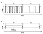
- FIG. 3 is a waveform diagram of a pulse current having two peaks used in gas shielded arc welding according to the present invention
- (a) to (d) are schematic diagrams showing a state of a droplet at a predetermined point in the waveform diagram.
- It is a waveform diagram of pulse current / voltage having two pulse periods used in gas shielded arc welding according to the present invention
- (a) is a waveform diagram of pulse current
- (b) is a waveform diagram of voltage. It is the base material used at the time of the gas shield arc welding in the Example which concerns on this invention.
- Example which concerns on this invention it is a schematic diagram explaining the movement of the wire performed at the time of gas shield arc welding, (a) is a schematic diagram explaining a horizontal attitude
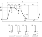
- the gas shielded arc welding is welding performed by generating an arc 2 between the solid wire 1 and a molten portion of the base material W (hereinafter also referred to as a molten pool).
- a molten pool a molten portion of the base material W
- galvanization with a low boiling point becomes the zinc gas 3
- this zinc gas 3 floats from the lower part to the upper part of the molten part.
- this zinc gas 3 is released from the upper surface of the melted part to the outside, there is no problem, but if it remains in the melted part and solidifies in that state, a blowhole that is a substantially spherical cavity is formed. Will be done. In addition, when the zinc gas 3 is solidified near the surface of the base material W, pits that are small recessed holes are formed.
- the zinc gas 3 generated from the lower part of the melted part can be easily released from the upper surface of the melted part to the outside, and the zinc gas 3 enters the melted part. This is based on the idea of finally suppressing the generation of pore defects by reducing the possibility of staying.
- the molten metal is held in a raised state as shown in FIG. 1 around the molten portion, and the molten metal flows into the molten portion.
- the thickness L of the molten portion of the base material W is controlled to be thin by combining the means for preventing the above and (ii) the means for greatly digging the molten portion directly below the solid wire 1 by increasing the arc force. . That is, according to the present invention (i) and (ii), the occurrence of pore defects can be suppressed by controlling the thickness L of the melted portion of the base material W to be thin.
- the above (i) is mainly controlled by restricting the composition of the solid wire, and the above (ii) mainly has a large CO 2 content in the shielding gas. Control by limiting to the range.
- the effect of suppressing the generation of pore defects can be further improved by combining means for vibrating the molten part (molten pool) so that the zinc gas 3 can easily escape from the molten part.
- the above (iii) is mainly controlled by using a pulse current that alternately repeats the first period and the second period at a predetermined frequency as the welding current.
- the present invention limits the CO 2 content ratio of the shielding gas to a large range in order to control the above (ii), when the CO 2 content ratio increases, the force to lift the droplets formed at the tip of the solid wire also increases. It gets bigger. As a result, the shape of the droplet usually changes and a large sputter of 1 mm or more is generated. However, the shape of the droplet is hardly changed by increasing the surface tension ST of the droplet (molten metal) by (i). As a result, according to the present invention (i), the occurrence of sputtering can be suppressed.
- (i) can be controlled mainly by limiting the composition of the solid wire.
- the above (iv) can be controlled by limiting the diameter of the solid wire, and the above (v) can be obtained by applying a predetermined pulse current having two peaks to the welding current. It can control by using as.
- Solid wire The solid wire according to the present invention (hereinafter also simply referred to as a wire) is a solid wire for welding a galvanized steel sheet as well as for gas shielded arc welding using a shielding gas.
- the solid wire according to the present invention contains a predetermined amount of C, Si, Mn, P, S, O, Cr, and the balance is composed of Fe and inevitable impurities, and Si, Mn, S, The content of O satisfies a predetermined relationship.
- C 0.15 mass% or less
- C is an element that improves the strength. If C is present in excess of 0.15% by mass, it may cause spattering frequently, so the content of C is preferably as low as possible and there is no problem even if it is free. Therefore, the C content is 0.15% by mass or less (including 0% by mass).
- Si 0.40-0.90 mass%
- Si is an effective deoxidizer and is an indispensable element in deoxidation of weld metal.
- Si content is less than 0.40% by mass, the deoxidation effect is impaired, the surface tension is lowered, and pore defects such as pits and blowholes are likely to occur.
- Si has a feature that the electrical resistance of the wire decreases as the content decreases, and the wire is less likely to melt as the electrical resistance of the wire decreases (the electrical resistance heat decreases). As a result, the arc force is increased, so that pore defects such as pits and blowholes can be suppressed.
- the Si content exceeds 0.90 mass%, the amount of slag generated on the bead surface increases. Accordingly, the Si content is set to 0.40 to 0.90 mass%.
- Mn is an effective deoxidizer similar to Si, and is an element that easily binds to S.
- Mn is an effective deoxidizer similar to Si, and is an element that easily binds to S.
- the content of Mn is less than 0.20% by mass, the deoxidation and desulfurization effects are impaired, the surface tension is lowered, and pore defects such as pits and blowholes are likely to occur.
- the Mn content exceeds 1.50% by mass, a thin oxide film that hardly peels off is generated on the bead surface. Therefore, the Mn content is 0.20 to 1.50 mass%.
- P 0.0500% by mass or less
- P is an element that is generally mixed as an impurity, and is preferably as low as possible from the viewpoint of weld cracking.
- P forms a stable compound (such as P—Zn) with zinc at a temperature equal to or higher than the melting point of zinc, and thus has an effect of improving the porosity resistance.
- the P content exceeds 0.0500% by mass, cracking occurs. Therefore, the P content is 0.0500% by mass or less (including 0% by mass).
- S is an element that lowers the surface tension of the molten metal when added in a small amount, and the content is preferably as small as possible. Specifically, when the S content exceeds 0.0080% by mass, the surface tension of the molten metal is excessively lowered, and pits and blowholes are easily generated. Therefore, the S content is 0.0080% by mass or less (including 0% by mass).
- O is an element that reduces the surface tension of the molten metal when added in a small amount, and the content is preferably as small as possible. Specifically, when the O content exceeds 0.0100 mass%, the surface tension of the molten metal is excessively lowered, and pits and blowholes are easily generated. Therefore, the O content is 0.0100% by mass or less (including 0% by mass).
- Cr is an element that increases viscosity when added to Fe.
- the viscosity of the wire increases, it is possible to prevent the weld metal from flowing too much directly under the arc.
- the Cr content exceeds 1.00% by mass, the viscosity becomes excessively high, the bead shape becomes convex, and the bead appearance becomes poor.
- the Cr content is 0.10 to 0.60 mass%, the porosity resistance can be improved more appropriately. Accordingly, the Cr content is 1.00% by mass or less, preferably 0.10 to 0.60% by mass.
- elements that greatly reduce the surface tension are oxygen (O) and sulfur (S). That is, it is necessary to suppress the addition of O and S elements as much as possible.
- elements such as O and S are easily bonded to Si and Mn, and by generating oxides and sulfides, the surface tension of O and S can be prevented and the surface tension can be kept high. Therefore, in this invention, it defines about the relationship of content of Si, Mn, S, and O, and content of O, S, Si, and Mn which satisfy
- the “element mass%” in the formula of the present invention including the formula (1) is the mass% of the element with respect to the total mass of the solid wire.
- the remainder of the solid wire is composed of Fe and unavoidable impurities.
- the unavoidable impurities include Cu, Mo, Al, Ti, Nb, Zr, and N, which are contained within a range that does not hinder the effects of the present invention. It is acceptable. Details are as follows.
- Cu and Mo are elements that increase the strength, and may be added when strength adjustment is necessary. If Cu exceeds 3.00% by mass, the wire is disconnected at the time of wire drawing, so the Cu content is 3.00% by mass or less. If Mo exceeds 5.00 mass%, weld cracking occurs due to excessive strength, so the Mo content is 5.00 mass% or less.
- Al, Ti, Nb, and Zr are strong deoxidizing elements, and can reduce the oxygen content of the molten metal and reduce the surface tension. Therefore, it is effective when the oxygen content in the wire is high. It is. However, if each amount exceeds 0.500% by mass, a large amount of slag is generated. Therefore, the contents of Al, Ti, Nb, and Zr are each 0.500% by mass or less.
- N is an element that is generally mixed as an impurity, and as the N content increases, an excessive increase in strength and porosity defects occur. In order to prevent these occurrences, the N content is set to 0.0200% by mass or less.
- the diameter of the solid wire is preferably 0.7 to 1.1 mm. More preferably, it is 0.8 to 1.0 mm.
- the shielding gas according to the present invention is Ar gas containing 25 to 40% CO 2 gas. That is, the shielding gas according to the present invention is Ar—CO 2 gas composed of 25 to 40% CO 2 gas and the balance Ar gas.
- Ar—CO 2 gas used for gas shielded arc welding has a CO 2 gas content of 20%. This is because when the CO 2 content ratio of the Ar—CO 2 gas is increased, a large amount of spatter is generated, and those having a CO 2 gas content exceeding 20% are hardly used.
- the conventional Ar—CO 2 gas having a CO 2 content ratio is not preferable because the arc force is small and the possibility of occurrence of pore defects such as pits and blowholes increases.
- the present invention by using the solid wire with a limited content of each element in a predetermined amount, even Ar-CO 2 gas containing CO 2 gas to 40% to suppress the generation of sputter
- Ar-CO 2 gas containing CO 2 gas to 40% to suppress the generation of sputter
- stable welding was possible, and the arc was concentrated by the characteristics of arc contraction possessed by CO 2 , and it was possible to increase the arc force (improve porosity).
- the content of CO 2 gas exceeds 40%, the generation of spatter cannot be suppressed.
- the content of CO 2 gas is less than 25%, sufficient arc force cannot be obtained. Accordingly, the CO 2 content ratio of Ar gas (Ar—CO 2 gas) as a shielding gas is 25 to 40%.
- the base material to be welded is a galvanized steel sheet.
- the galvanized steel sheet is a plate material in which a galvanized film is formed on the surface of the steel sheet, and the composition, thickness, etc. of the steel sheet are not particularly limited. Further, the basis weight of galvanization on the surface of the base material is not particularly limited.
- a solid wire is fed into a shielding gas that is Ar gas (Ar—CO 2 gas), and a welding current is supplied to the solid wire.
- the welding is performed by generating an arc between the base material and the galvanized steel sheet.
- the welding current used in the gas shielded arc welding method according to the present invention is preferably a pulse current.
- the pulse current is preferably one in which the first peak energization, the second peak energization, and the base current energization are repeated in one pulse cycle.
- the pulse current 10 includes a peak rising period Tup, a first peak period Tp1, a transition period Tsf, a second peak period Tp2, and a peak falling period Tdn.
- the base period Tb is repeated as one pulse period Tf.
- Ar gas having a high CO 2 content ratio that is, a gas having a low Ar content ratio
- a gas having a low Ar content ratio pulse current welding is performed.
- the arc generation position is a low position on the side of the solid wire (position close to the solid wire tip)
- the droplet formed on the solid wire tip cannot be sufficiently squeezed by the pinch force, and is appropriate. It becomes difficult to generate a spray arc.
- the present invention uses the pulse current as described above as the welding current, so that the arc generation position is located at a high position on the side surface of the solid wire (position far from the solid wire tip) by the pulse current in the first peak period Tp1.
- the pinch force was appropriately applied to the entire droplet formed on the solid wire tip.
- by providing the pulse current with the second peak period Tp2 it is avoided that the pulse area of one cycle is excessive, and the occurrence of welding defects such as cuts is avoided.
- the arc In order to appropriately apply a pinch force to the entire droplet formed on the solid wire tip during the first peak period Tp1, the arc is located at a position closer to the base end than the wire tip (wire liquefaction start portion), that is, It is necessary to generate from a high position on the side of the wire (a position far from the solid wire tip).
- the current value Ip1 of the first peak of the pulse current is less than 440 A, no arc is generated from a sufficiently high position on the side surface of the wire.
- the current value Tp1 of the first peak exceeds 500 A, the side surface of the wire is excessively melted. Therefore, the current value Ip1 of the first peak is preferably 440 to 500A.
- the first peak period Tp1 is a period necessary to squeeze the upper side surface of the droplet formed on the wire tip by the pinch force. On the other hand, if it exceeds 0.6 ms, the droplets are excessively stretched, and a short circuit (short) that causes the occurrence of spatter tends to occur. Therefore, the first peak period Tp1 is preferably 0.2 to 0.6 ms.
- the second peak period Tp2 In the second peak period Tp2, among the droplets formed at the tip of the wire, the middle and lower droplets are wrapped with an arc and appropriately separated by a pinch force.
- the current value Ip2 of the second peak is less than 300 A, it is difficult to form a spray arc, and an arc is generated from the lowest part of the droplet formed at the wire tip, and the droplet transfer is excellent. Will not be performed.
- the current exceeds 400 A there is no difference from the current value of the first peak, the current value as a whole (average current value) increases, that is, the pulse area becomes excessive, and when applied to high-speed welding, it is cut at the bead end. Such a welding defect is likely to occur. Therefore, the current value Ip2 of the second peak is preferably 300 to 400A.
- the second peak period Tp2 is less than 0.2 ms, it is not possible to secure a time for squeezing the droplets with a pinch force. Short-circuiting that causes generation is likely to occur. Therefore, the period Tp2 of the second peak is preferably 0.2 to 0.6 ms.
- the transition period Tsf from the first peak to the second peak is preferably 0.2 to 0.6 ms, which is the same as the first peak period Tp1, so that the pulse area does not become excessive.
- the base current value Ib and the period Tb are not particularly limited, but it is preferably 20 to 80 A for the current value Ib and 0.5 to 20 ms for the period Tb.
- the peak rising period Tup and the peak falling period Tdn are not particularly limited, but the period Tup is preferably 0.4 to 0.8 ms, and the period Tdn is preferably 0.4 to 1.2 ms.
- the first peak period Tp1 a pinch force acts on the entire droplet 4 formed at the tip of the solid wire 1 (see FIG. 2A).
- the middle and lower droplets 4 of the droplets 4 formed at the tip of the solid wire 1 are wrapped with an arc and are being separated by a pinch force (see FIG. 2B).
- the spherical droplet 5 is separated from the droplet 4 formed at the tip of the solid wire 1 (see FIG. 2C). Thereafter, in the base period Tb, the separated droplet 5 is transferred to the welded portion. (See FIG. 2 (d)).
- the pulse current alternately repeats a first period P1 in which one pulse period is densely continuous and a second period P2 in which one pulse period is sparsely continuous at a predetermined frequency. It is preferable.
- the pulse current includes a first period P1 in which a pulse wave whose one pulse period is a predetermined period densely continues, and a second period P2 in which a pulse wave whose one pulse period is longer than the predetermined period is sparsely continuous. Are preferably alternately repeated at a predetermined frequency.
- the current value of the welding current is approximately proportional to the wire feed speed, and the wire feed speed must be set in relation to the welding amount determined by the welding speed and the bead cross section. Only the current value of the current cannot be set freely large.
- the welding current in the first period P1 is increased without changing the average welding current, and the welding current in the second period P2. Can be reduced. Therefore, in the first period P1, it is possible to push the molten metal directly under the solid wire and dig deeper the molten portion with a large arc force.
- the molten metal in the solidification process can be periodically vibrated, and is contained in the molten part by the vibration.
- the zinc gas 3 can be discharged to the outside.
- the pulse current repeats the first period P1 and the second period P2 at a frequency of 5 to 30 Hz.
- the pulse current is preferably one in which the first period P1 and the second period P2 are one cycle and the cycle is repeated at a frequency of 5 to 30 Hz.
- the length of one pulse period is not particularly limited, but one pulse period in the first period P1 is preferably 2 to 25 ms, and one pulse period in the second period P2 is preferably 2 to 25 ms. .
- the pulse current is one in which the first period P1 in which one pulse period is densely repeated and the second period P2 in which one pulse period is sparsely repeated are alternately repeated at a predetermined frequency.
- One pulse period in P1 and the second period P2 may be configured from the first peak energization, the second peak energization, and the base current energization.
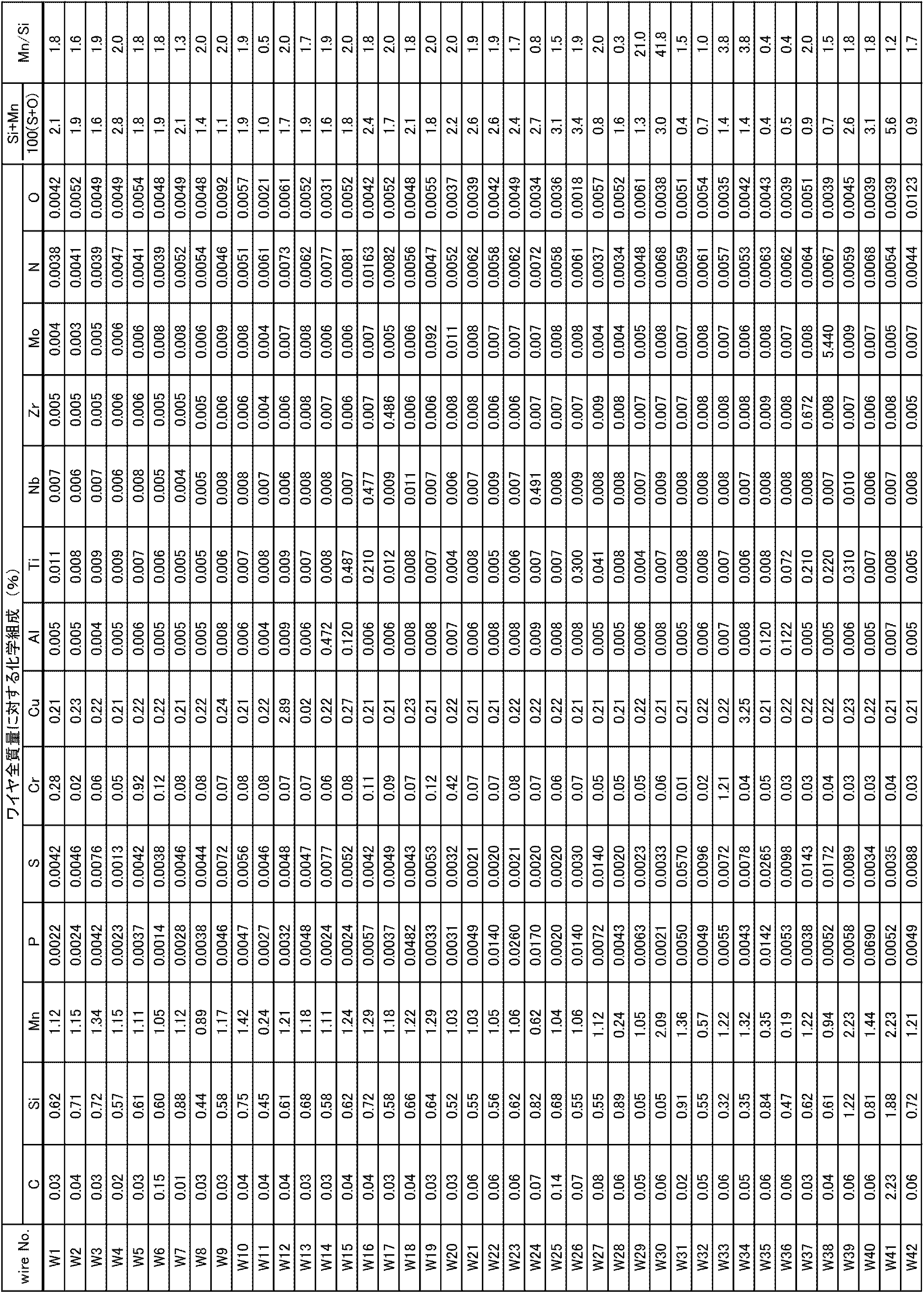
- Solid wire, shielding gas Solid wires having the compositions shown in Table 1 (wire Nos. W1 to W42) were used.
- the base material was SGCC (hot dip galvanized steel sheet) based on JIS G 3302, and the basis weight of galvanization was 45 g / m 2 . Then, as shown in FIG. 4, two hot-dip galvanized steel sheets (300 mm ⁇ 55 mm ⁇ 2.3 mm) are shifted and overlapped by 25 mm, and bonded (temporarily attached) by spot welding with a welding gap of 0 mm. Created conditions that are likely to occur.
- SGCC hot dip galvanized steel sheet
- the pulse waveform of the pulse current used as the welding current was specifically the waveform shown in FIG.
- the CO 2 gas content of the shielding gas was 25 to 40%, welding was performed with 1V higher than the above voltage, and when it exceeded 40%, it was increased by 2V.
- the voltage in the first period-second period 27 V-25 V
- the distance between the base material and the chip 12 mm
- the flow rate 25 liter / min
- the welding speed 100 cm / min
- Welding was performed under the condition of wire feed speed: 2000 cm / min.
- blowhole measurement method and evaluation criteria The blowhole is measured by a method based on a radiation transmission test (RT: see JIS Z 3104), the number of blowholes in a bead in 250 mm is measured, and the average value of two measurements is calculated. Evaluation was performed by value.
- the measurement of generated spatter is common to each example, and welding is performed in a box made of a copper plate having a height of 300 mm ⁇ width of 300 mm ⁇ length of 450 mm, and all spatter generated in one minute is collected from the box and collected. The total mass of the sputter was measured to obtain the spatter amount (g / min).
- the slag coverage was measured from the area of the bead appearance (bead 250 mm) taken with a digital camera and binarized to separate the slag and the metal surface. When the coverage ratio exceeded 15%, the bead appearance was poor, and therefore, it was evaluated as defective (x), and when it was 15% or less, it was evaluated as good ( ⁇ ).
- Tables 2A to 5 show the results of welding using each solid wire under predetermined welding conditions.
- the underline in the table indicates that the requirement of the present invention is not satisfied.
- Ar + numerical value CO 2 indicates Ar—CO 2 gas composed of a numerical value of CO 2 gas and the balance Ar gas.
- the wave frequency in the table is a cycle in which the first period (period in which one pulse period is densely continuous) and the second period (period in which one pulse period is sparsely continuous) are defined as one cycle. Indicates the frequency.
- Tables 2A and 2B show the results when the composition of the solid wire and the composition of the shield gas are changed.
- Test No. in Table 2A 1 to 32 are examples of the present invention. In either case, the number of pits, the number of blow holes, and the amount of spatter were reduced, the slag coverage was suppressed, and the bead appearance was good.
- Test No. 13 (wire No. W13) was not subjected to copper plating, but it was found that the same effect as other plated wires was obtained.
- Test No. Nos. 27 to 32 were obtained by greatly increasing the CO 2 content of the shielding gas compared to the conventional one (Ar-20% CO 2 ), but it was found that very good porosity resistance was obtained. .
- test No. in Table 2B. 33 to 57 are comparative examples of the present invention.
- test No. 33 to 49 the CO 2 content of the shielding gas was within the range specified in the present invention. However, test no. Since No. 33 had a high S content, the surface tension was low, and many pits and blowholes were generated.
- Test No. No. 44 had a large content of S and a large content of Mo, so that cracks occurred on the bead surface and many pits and blowholes occurred.
- Test No. No. 46 had a large P content, so cracking occurred on the bead surface.
- Test No. Nos. 51 to 53 had many pits and blowholes because the shielding gas had a low CO 2 content.
- Table 3 shows the results when the diameter of the solid wire, the composition of the solid wire, and the composition of the shielding gas are changed.
- Test No. in Table 3 58 to 79 are examples of the present invention. In either case, the number of pits, the number of blow holes, and the amount of spatter were reduced, the slag coverage was suppressed, and the bead appearance was good.
- test No. in Table 3 80 to 85 are comparative examples of the present invention.
- Tables 4A and 4B show the results when the pulse current waveform, the diameter of the solid wire, and the composition of the shield gas are changed.
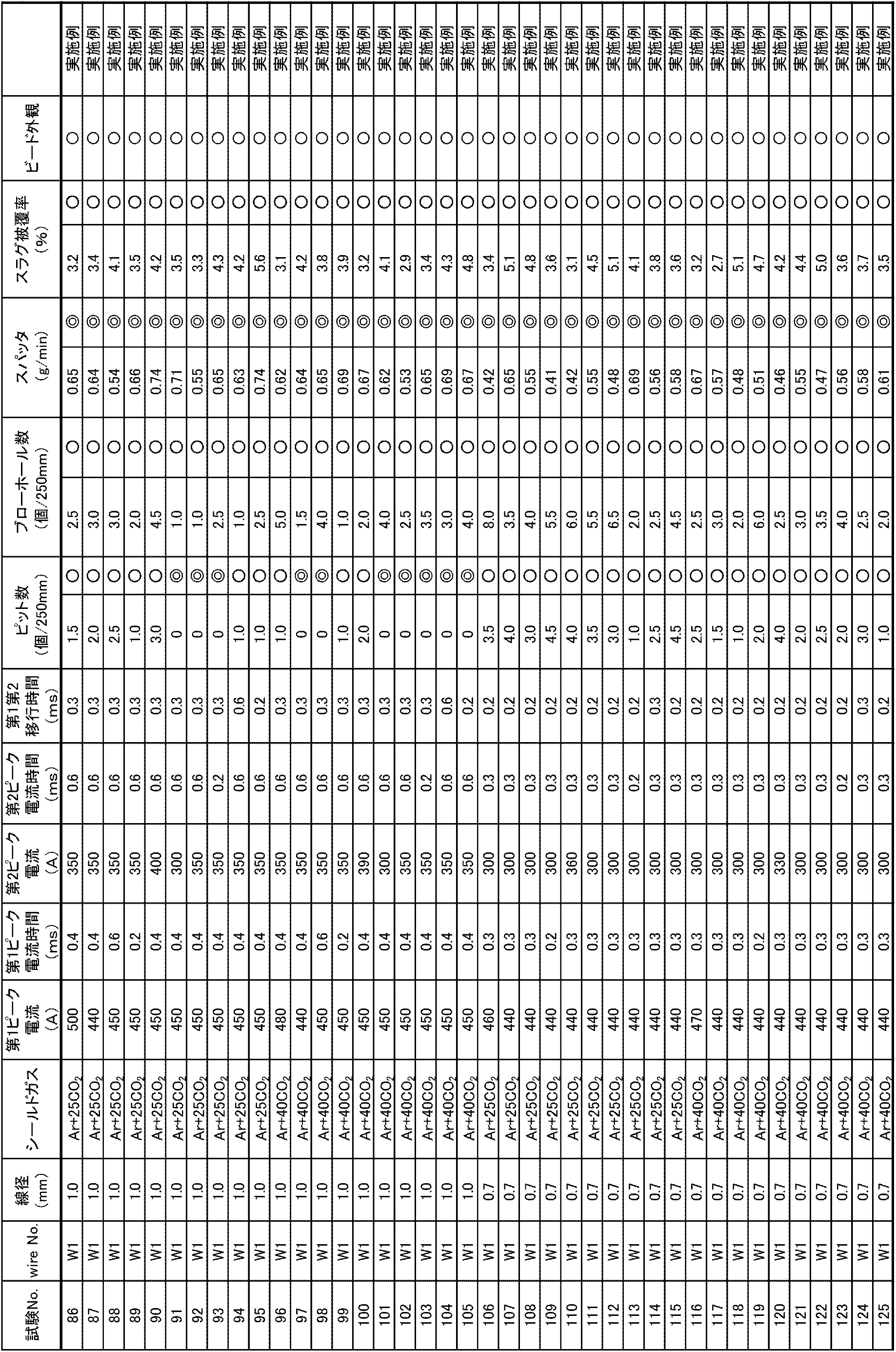
- Test No. in Tables 4A and 4B 86 to 165 are examples of the present invention. In either case, the number of pits, the number of blow holes, and the amount of spatter were reduced, the slag coverage was suppressed, and the bead appearance was good.
- test no. Nos. 86 to 125 use a pulse current that satisfies the conditions of the first peak current value and period, the second peak current value and period, and the transition period defined by the present invention, so the sputtering suppression effect is extremely good. As a result, the pit and blowhole suppression effect was also better than the result.
- test no. Nos. 126 to 165 used pulse currents that did not satisfy any of the conditions of the first peak current value and period, the second peak current value and period, and the transition period defined in the present invention. . Compared to 86 to 125, one of the pit suppression effect, blowhole suppression effect, and sputtering suppression effect was slightly inferior.
- test no. For 126 to 135, 139, 143, and 146 to 165, the blowhole suppression effect was good, but it was 8.5 pieces / 250 mm or more. Compared with 86-125, the result of the blowhole suppression effect was slightly inferior.
- test no. For 126, 127, 129, 131, 133, 135 to 147, 149, 151, 153, 155 to 157, 159, 161, 163, and 165, the sputter suppression effect was good or relatively good, and the test No. . Compared with 86-125, the sputtering suppression effect was slightly inferior.
- Table 5 shows the results when the pulse frequency of the pulse current, the diameter of the solid wire, and the composition of the shielding gas are changed.
- Reference numerals 166 to 201 are examples of the present invention. In either case, the number of pits, the number of blow holes, and the amount of spatter were reduced, the slag coverage was suppressed, and the bead appearance was good.
- test no. 166 to 189 use a pulse current that repeats the first period and the second period at a predetermined frequency defined by the present invention, resulting in extremely good pit suppression effect and sputtering suppression effect, The result of the blowhole suppression effect was also good.
- test no. Nos. 190 to 201 used test currents No. 190 and No. 201 because pulse currents that do not satisfy the condition of repeating the first period and the second period at a predetermined frequency defined by the present invention were used. Compared with 166 to 189, one of the pit suppression effect, blowhole suppression effect, and sputtering suppression effect was slightly inferior.
- test no. For 190, 191, 193, 194, and 196 to 201, the results showed that the pit suppression effect was good, and test no. Compared with 166 to 189, the pit suppression effect was slightly inferior.
- test no. For 190, 191, 193, 194, 196, 197, 199, and 200, the results of test No. Compared with 166 to 189, the blowhole suppression effect was slightly inferior.
- test no. For 190, 192, 193, 195, 196, and 199, only the results of good sputtering suppression effects were obtained. Compared with 166 to 189, the sputtering suppression effect was slightly inferior.
Landscapes
- Engineering & Computer Science (AREA)
- Mechanical Engineering (AREA)
- Physics & Mathematics (AREA)
- Plasma & Fusion (AREA)
- Chemical & Material Sciences (AREA)
- Materials Engineering (AREA)
- Arc Welding In General (AREA)
- Arc Welding Control (AREA)
Description
まず、亜鉛めっき鋼板のガスシールドアーク溶接時において、気孔欠陥およびスパッタの発生を抑制するメカニズムについて、図1を用いて簡単に説明する。
ガスシールドアーク溶接とは、ソリッドワイヤ1と母材Wの溶融部(以下、溶融池ともいう)との間にアーク2を発生させて行う溶接である。ここで、母材Wが亜鉛めっき鋼板である場合、アーク2の熱により、沸点の低い亜鉛めっきが亜鉛ガス3となり、この亜鉛ガス3が溶融部の下部から上部へと浮上する。
本発明は、前記(ii)を制御するためにシールドガスのCO2含有割合を大きい範囲に制限しているが、CO2含有割合が大きくなると、ソリッドワイヤ先端に形成される溶滴を持ち上げる力も大きくなってしまう。その結果、通常では、溶滴の形状が変化し、1mm以上の大きなスパッタを発生させることとなってしまう。しかし、前記(i)により、溶滴(溶融金属)の表面張力STを高くすることで、溶滴の形状が変化し難くなる。その結果、本発明は、前記(i)により、スパッタの発生を抑制することができる。
本発明に係るソリッドワイヤ(以下、単に、ワイヤともいう)は、シールドガスを用いるガスシールドアーク溶接用であるとともに、亜鉛めっき鋼板溶接用のソリッドワイヤである。
Cは、強度を向上させる元素である。Cは、0.15質量%を超えて過剰に存在するとスパッタが多発する原因にもなるため、Cの含有量は少ない程好ましく、フリーでも問題は無い。したがって、Cの含有量は、0.15質量%以下(0質量%も含む)とする。
Siは、有効な脱酸剤であり、溶接金属の脱酸においては不可欠な元素である。Siの含有量が0.40質量%未満であると脱酸効果が損なわれ、表面張力が低下し、ピットやブローホールといった気孔欠陥が発生しやすくなる。一方、Siは、含有量が低くなるほどワイヤの電気抵抗が低くなるという特徴を持ち、ワイヤの電気抵抗が低くなるほどワイヤは溶融し難くなる(電気抵抗熱が低くなる)ため、必要な溶接電流は大きくなり、その結果、アーク力が高くなることにより、ピット、ブローホール等の気孔欠陥を抑制することができる。また、Siの含有量が0.90質量%を超えるとビード表面に発生するスラグ量が多くなってしまう。したがって、Siの含有量は、0.40~0.90質量%とする。
Mnは、Siと同じく有効な脱酸剤であり、Sと結合し易い元素である。Mnの含有量が0.20質量%未満であると、脱酸、脱硫効果が損なわれ、表面張力が低下し、ピットやブローホールといった気孔欠陥が発生しやすくなる。一方、Mnの含有量が1.50質量%を超えると、ビード表面に剥離し難い薄い酸化膜を発生させてしまう。したがって、Mnの含有量は、0.20~1.50質量%とする。
Pは、一般的に不純物として混入する元素であり、溶接割れの観点から出来るだけ含有量は少ない方が好ましい。一方で、亜鉛めっき鋼板の溶接において、Pは亜鉛の融点以上の温度で亜鉛と安定な化合物(P-Zn系等)を形成するため、耐気孔性を向上させる効果を有する。しかし、Pの含有量が0.0500質量%を超えると、割れを発生させてしまう。したがって、Pの含有量は、0.0500質量%以下(0質量%も含む)とする。
Sは、少量の添加で溶融金属の表面張力を低下させる元素であり、含有量は極力少ないほうが好ましい。詳細には、Sの含有量が0.0080質量%を超えると、溶融金属の表面張力が過剰に低下し、ピット、ブローホールが発生し易くなる。
したがって、Sの含有量は、0.0080質量%以下(0質量%も含む)とする。
Oは、Sと同様に少量の添加で溶融金属の表面張力を低下させる元素であり、含有量は極力少ないほうが好ましい。詳細には、Oの含有量が0.0100質量%を超えると、溶融金属の表面張力が過剰に低下し、ピット、ブローホールが発生し易くなる。したがって、Oの含有量は、0.0100質量%以下(0質量%も含む)とする。
Crは、Feに添加すると粘性を増加させる元素である。そして、ワイヤの粘性が増加するとアーク直下に溶接金属が流入し過ぎるのを防止することができる。ただし、Crの含有量が1.00質量%を超えると粘性が過剰に高くなり、ビード形状が凸型となり、ビード外観が粗悪となる。なお、Crの含有量が0.10~0.60質量%であると、耐気孔性をより適切に向上させることができる。したがって、Crの含有量は、1.00質量%以下であり、好ましくは、0.10~0.60質量%である。
前記のとおり、気孔欠陥の発生を抑制するためには、溶融金属の表面張力を高くする必要があり、この溶融金属の表面張力はソリッドワイヤの化学組成に依存する。
Si、Mnの含有量が、前記式(1)の範囲を満たしても、Mn質量%/Si質量%比が十分に高くないと有用な脱酸速度が得られない。詳細には、Mn質量量%/Si質量%の値が0.50未満であると、十分な脱酸作用が得られないため、酸素が過剰となり、溶融金属の表面張力が低下し、その結果、ピットやブローホールといった気孔欠陥が発生し易くなる。一方、Mn質量量%/Si質量%の値が2.00を超えると、Mnの含有比率が大きくなることで、ビード表面に剥離し難いMn酸化物が生成し、その結果、ビード外観が粗悪となる。したがって、Mn質量%/Si質量%比を以下の式(2)の範囲に設定する。
ソリッドワイヤの残部は、Feおよび不可避的不純物からなり、当該不可避的不純物としては、Cu、Mo、Al、Ti、Nb、Zr、N等が挙げられ、本発明の効果を妨げない範囲で含有することが許容される。詳細には以下の通りである。
ソリッドワイヤの直径は、小さいほどピンチ力がかかり易く、溶滴移行がスムーズとなる。しかし、直径が0.7mm未満であると、アーク力の低下により、ピットやブローホールといった気孔欠陥が発生し易くなる。一方、直径が1.1mmを超えると、ソリッドワイヤ先端の溶滴が粗大化するため、1mm以上の径を呈する大きなスパッタが発生し易くなる。したがって、ソリッドワイヤの直径は、0.7~1.1mmであることが好ましい。なお、より好ましくは、0.8~1.0mmである。
本発明に係るシールドガスは、25~40%のCO2ガスを含むArガスである。つまり、本発明に係るシールドガスは、25~40%のCO2ガスと、残部がArガスと、からなるAr-CO2ガスである。
溶接対象となる母材は、亜鉛めっき鋼板である。そして、亜鉛めっき鋼板は、鋼板の表面に亜鉛めっき皮膜が形成された板材であって、鋼板の組成、厚さ等については特に限定されない。また、母材表面に対する亜鉛めっきの目付け量についても特に限定されない。
次に、ガスシールドアーク溶接方法を説明する。
本発明に係るガスシールドアーク溶接方法で用いる溶接電流は、パルス電流であることが好ましい。そして、パルス電流は、第1ピークの通電、第2ピークの通電およびベース電流の通電を1パルス周期として繰り返すものであることが好ましい。
第1ピークの期間Tp1において、ソリッドワイヤ先端に形成される溶滴全体に適切にピンチ力を作用させるためには、アークは、ワイヤ先端(ワイヤ液化開始部)よりも基端側の位置、つまり、ワイヤ側面の高い位置(ソリッドワイヤ先端から遠い位置)から発生させる必要がある。ここで、パルス電流の第1ピークの電流値Ip1が440A未満であると、ワイヤ側面の十分に高い位置からアークが発生しない。一方、第1ピークの電流値Tp1が500Aを超えると、ワイヤ側面を過剰に溶融させてしまう。したがって、第1ピークの電流値Ip1は、440~500Aが好ましい。
第2ピークの期間Tp2において、ワイヤ先端に形成された溶滴のうち中下部の溶滴をアークで包み、ピンチ力で適切に切り離すこととなる。ここで、第2ピークの電流値Ip2が300A未満であると、スプレーアークになり難く、ワイヤ先端に形成された溶滴の最下部からアークが発生する状態となってしまい、良好な溶滴移行が行われなくなる。一方、400Aを超えると、第1ピークの電流値と差異がなくなり、電流値全体(平均電流値)が高くなる、つまり、パルス面積が過大となってしまい、高速溶接に適用するとビード端にカット等の溶接欠陥が発生し易くなる。したがって、第2ピークの電流値Ip2は、300~400Aであることが好ましい。
パルス電流は、図3(a)に示すように、1パルス周期が密に連続する第1期間P1と、1パルス周期が疎に連続する第2期間P2と、を所定の周波数で交互に繰り返すものであることが好ましい。言い換えると、パルス電流は、1パルス周期が所定期間であるパルス波が密に連続する第1期間P1と、1パルス周期が前記所定期間よりも長いパルス波が疎に連続する第2期間P2と、を所定の周波数で交互に繰り返すものであることが好ましい。
第1期間P1と第2期間P2とを繰り返す周波数が5Hz未満であると、1パルス周期が疎に連続する第2期間P2が長くなるため、当該期間において適切に亜鉛めっきの蒸発を促し難くなる。また、ビード外観に不均一な波目がついてしまう。
ソリッドワイヤは、表1に示す組成(wire No.W1~W42)のものを使用した。
母材は、JIS G 3302に準拠したSGCC(溶融亜鉛めっき鋼板)であって、亜鉛めっきの目付け量が45g/m2のものを用いた。そして、図4に示すように、2枚の溶融亜鉛めっき鋼板(300mm×55mm×2.3mm)を25mmだけずらして重ね、溶接ギャップ0mmとして、スポット溶接で接着(仮着け)し、気孔欠陥が発生し易い条件を作った。
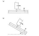
図4に示すように、スポット溶接で接着された2枚の前記母材の隅部6に対して重ね溶接(250mm)を行うという方法で溶接を行った。そして、図4に示すようなビード7を形成させた。なお、表2A~5に記載の試験No.1~201については、図5(b)に示す下進姿勢(水平面に対し30°)であるとともに、トーチ角度が母材面に対して垂直となる状態で溶接を行った。
ピットの測定は目視で行い、250mmのビード中のピット個数を測定し、2回の測定値の平均の値を算出し、当該値で評価を行った。
ブローホールの測定は放射線透過試験(RT:JIS Z 3104参照)に準拠した方法で行い、250mm中のビード中のブローホール個数を測定し、2回の測定値の平均の値を算出し、当該値で評価を行った。
発生したスパッタの測定は、各例とも共通して、銅板で作成した高さ300mm×横300mm×縦450mmの箱中で溶接を行い、1分間に発生したスパッタ全てを箱内から採取し、集めたスパッタの全質量を測定してスパッタ量(g/min)とした。
スラグ被覆率はビード外観(ビード250mm分)をデジタルカメラにて撮影し、その画像を2値化することにより、スラグと金属面を分け、その面積から測定した。被覆率が15%を超える場合はビード外観が粗悪なものとなるため、不良(×)と評価し、15%以下の場合は良好(〇)と評価した。
ビード外観の確認は目視で行い、ビード表面において、蛇行、ハンピング、アンダカット等の溶接欠陥、スラグ被覆の存在の有無を確認した。前記のような溶接欠陥・スラグ被覆がビード表面に存在する場合を不良(×)と評価し、存在しない場合を良好(○)と評価した。なお、スラグ被覆の有無の基準については前記基準(15%を超える場合を有と評価)による。


2 アーク
3 亜鉛ガス
4 ソリッドワイヤ先端に形成された溶滴(溶滴、溶融金属)
5 球状を呈する溶滴(溶滴、溶融金属)
6 隅部
7 ビード
10 パルス電流(本発明)
20 パルス電流(従来)
W 母材(亜鉛めっき鋼板)
ST 表面張力
Tup ピーク立上り期間
Tp1 第1ピークの期間
Tsf 移行期間
Tp2 第2ピークの期間
Tdn ピーク立下り期間
Tb ベース期間
Tf 1パルス周期
P1 第1期間
P2 第2期間
Claims (5)
- シールドガスを用いるガスシールドアーク溶接用であるとともに、亜鉛めっき鋼板溶接用のソリッドワイヤであって、
前記ソリッドワイヤは、当該ソリッドワイヤ全質量に対し、
C:0.15質量%以下、
Si:0.40~0.90質量%、
Mn:0.20~1.50質量%、
P:0.0500質量%以下、
S:0.0080質量%以下、
O:0.0100質量%以下、
Cr:1.00質量%以下、
を含有し、残部がFeおよび不可避的不純物であり、
前記ソリッドワイヤは、
1.0≦(Si質量%+Mn質量%)/{100(S質量%+O質量%)}≦4.0
0.50≦Mn質量%/Si質量%≦2.00
を満足し、かつ
前記シールドガスは、25~40%のCO2ガスを含むArガスであることを特徴とするソリッドワイヤ。 - ワイヤ直径が、0.7~1.1mmであることを特徴とする請求項1に記載のソリッドワイヤ。
- 請求項1または請求項2に記載のソリッドワイヤを、25~40%のCO2ガスを含むArガスであるシールドガス中に送給し、当該ソリッドワイヤに溶接電流を供給することで、当該ソリッドワイヤと母材である亜鉛めっき鋼板との間にアークを発生させて溶接を行うことを特徴とするガスシールドアーク溶接方法。
- 前記溶接電流は、パルス電流であって、
前記パルス電流は、第1ピークの通電、第2ピークの通電およびベース電流の通電を1パルス周期として繰り返すものであって、
前記第1ピークの電流値が440~500A、前記第1ピークの期間が0.2~0.6msであり、
前記第2ピークの電流値が300~400A、前記第2ピークの期間が0.2~0.6msであり、
前記第1ピークから前記第2ピークに移行する期間が0.2~0.6msであることを特徴とする請求項3に記載のガスシールドアーク溶接方法。 - 1パルス周期が密に連続する第1期間と、1パルス周期が疎に連続する第2期間と、を交互に繰り返すパルス電流を前記溶接電流として用い、
前記第1期間と前記第2期間とを、5~30Hzの周波数で繰り返すことを特徴とする請求項3または請求項4に記載のガスシールドアーク溶接方法。
Priority Applications (5)
| Application Number | Priority Date | Filing Date | Title |
|---|---|---|---|
| EP13758142.7A EP2823931B1 (en) | 2012-03-09 | 2013-02-28 | Solid wire, and gas-shielded arc welding method using same |
| ES13758142T ES2745256T3 (es) | 2012-03-09 | 2013-02-28 | Alambre sólido y método de soldadura con arco sumergido en gas inerte |
| US14/382,691 US9616528B2 (en) | 2012-03-09 | 2013-02-28 | Solid wire, and gas-shielded arc welding method using same |
| CN201380012352.2A CN104159700B (zh) | 2012-03-09 | 2013-02-28 | 实芯焊丝和使用其的气体保护电弧焊方法 |
| KR1020147024920A KR101623676B1 (ko) | 2012-03-09 | 2013-02-28 | 솔리드 와이어 및 이것을 이용한 가스 실드 아크 용접 방법 |
Applications Claiming Priority (2)
| Application Number | Priority Date | Filing Date | Title |
|---|---|---|---|
| JP2012-053779 | 2012-03-09 | ||
| JP2012053779A JP5787798B2 (ja) | 2012-03-09 | 2012-03-09 | ソリッドワイヤおよびこれを用いたガスシールドアーク溶接方法 |
Publications (1)
| Publication Number | Publication Date |
|---|---|
| WO2013133140A1 true WO2013133140A1 (ja) | 2013-09-12 |
Family
ID=49116621
Family Applications (1)
| Application Number | Title | Priority Date | Filing Date |
|---|---|---|---|
| PCT/JP2013/055567 Ceased WO2013133140A1 (ja) | 2012-03-09 | 2013-02-28 | ソリッドワイヤおよびこれを用いたガスシールドアーク溶接方法 |
Country Status (7)
| Country | Link |
|---|---|
| US (1) | US9616528B2 (ja) |
| EP (1) | EP2823931B1 (ja) |
| JP (1) | JP5787798B2 (ja) |
| KR (1) | KR101623676B1 (ja) |
| CN (1) | CN104159700B (ja) |
| ES (1) | ES2745256T3 (ja) |
| WO (1) | WO2013133140A1 (ja) |
Families Citing this family (27)
| Publication number | Priority date | Publication date | Assignee | Title |
|---|---|---|---|---|
| US10646949B2 (en) * | 2014-01-31 | 2020-05-12 | Nippon Steel Corporation | Spot welded joint and spot welding method |
| JP6430139B2 (ja) * | 2014-04-18 | 2018-11-28 | 岩谷産業株式会社 | 鋼材のmag溶接方法 |
| JP6412817B2 (ja) * | 2015-03-24 | 2018-10-24 | 岩谷産業株式会社 | 亜鉛めっき鋼板の溶接方法 |
| JP6114785B2 (ja) * | 2015-05-29 | 2017-04-12 | 日新製鋼株式会社 | 溶接部外観と溶接強度に優れた溶融Zn系めっき鋼板のアーク溶接方法、および溶接部材の製造方法 |
| JP6518160B2 (ja) | 2015-07-27 | 2019-05-22 | 株式会社神戸製鋼所 | 亜鉛めっき鋼板の溶接方法 |
| JP6762131B2 (ja) * | 2016-04-28 | 2020-09-30 | 株式会社神戸製鋼所 | フラックス入りワイヤ |
| JP6487877B2 (ja) * | 2016-06-20 | 2019-03-20 | 日新製鋼株式会社 | 溶融Zn系めっき鋼板のアーク溶接方法、溶接部材の製造方法および溶接部材 |
| JP6385411B2 (ja) | 2016-10-28 | 2018-09-05 | 日新製鋼株式会社 | 溶接部材およびその製造方法 |
| US11815127B2 (en) * | 2016-12-23 | 2023-11-14 | Posco Co., Ltd | Welded member for plated steel plate excellent in weld zone porosity resistance and fatigue properties and method for manufacturing the same |
| JP6285062B1 (ja) * | 2017-03-02 | 2018-02-28 | 日新製鋼株式会社 | 溶融Zn系めっき鋼板のアーク溶接方法および溶接部材の製造方法 |
| MX2019010305A (es) * | 2017-03-02 | 2019-10-21 | Kobe Steel Ltd | Procedimiento de soldeo por arco. |
| JP6904162B2 (ja) * | 2017-08-24 | 2021-07-14 | 日本製鉄株式会社 | 溶融Zn系めっき鋼板のアーク溶接方法および溶接部材の製造方法 |
| JP6941410B2 (ja) * | 2017-08-31 | 2021-09-29 | 株式会社ダイヘン | パルスアーク溶接制御方法 |
| JP7048382B2 (ja) * | 2018-03-28 | 2022-04-05 | 株式会社神戸製鋼所 | ガスシールドアーク溶接の制御方法及び制御装置 |
| MX2019007638A (es) * | 2018-06-18 | 2020-08-17 | Posco | Miembro soldado para placa de acero enchapada excelente en resistencia a la porosidad en la zona soldada y propiedades de fatiga y método para fabricar la misma. |
| JP7146571B2 (ja) * | 2018-10-25 | 2022-10-04 | 株式会社神戸製鋼所 | ガスシールドアーク溶接方法 |
| KR102135663B1 (ko) * | 2019-02-15 | 2020-07-21 | 현대종합금속 주식회사 | Co2 100% 가스를 이용한 플럭스-코어-와이어 용 펄스용접 파형제어방법 |
| JP7267770B2 (ja) | 2019-02-25 | 2023-05-02 | 株式会社神戸製鋼所 | めっき鋼板の接合方法及び接合構造体 |
| JP7352253B2 (ja) * | 2019-05-13 | 2023-09-28 | 国立大学法人大阪大学 | 機械部品 |
| US20220402078A1 (en) * | 2019-10-31 | 2022-12-22 | Jfe Steel Corporation | Mig welding method |
| WO2021210335A1 (ja) * | 2020-04-15 | 2021-10-21 | Jfeスチール株式会社 | アーク溶接継手およびアーク溶接方法 |
| EP4144478B1 (en) * | 2020-04-28 | 2025-09-10 | Posco | Welding wires for obtaining giga-grade welds, welded structures manufactured using same, and welding method thereof |
| JP7522632B2 (ja) * | 2020-10-14 | 2024-07-25 | 株式会社ダイヘン | ガスシールドアーク溶接方法及びガスシールドアーク溶接装置 |
| MX2023012393A (es) * | 2021-04-28 | 2023-11-06 | Jfe Steel Corp | Union soldada por arco y metodo de soldadura por arco. |
| US20240198447A1 (en) * | 2021-04-28 | 2024-06-20 | Jfe Steel Corporation | Arc welded joint and arc welding method |
| MX2023012392A (es) * | 2021-04-28 | 2023-11-06 | Jfe Steel Corp | Union soldada por arco y metodo de soldadura por arco. |
| JP7473508B2 (ja) * | 2021-08-20 | 2024-04-23 | 株式会社神戸製鋼所 | 造形物の評価方法及び造形物の製造方法 |
Citations (8)
| Publication number | Priority date | Publication date | Assignee | Title |
|---|---|---|---|---|
| JPS63242488A (ja) | 1987-03-30 | 1988-10-07 | Daido Steel Co Ltd | ガスシ−ルドア−ク溶接用ワイヤ |
| JPH01143775A (ja) | 1987-11-28 | 1989-06-06 | Nippon Steel Corp | 亜鉛メッキ鋼板のアーク溶接方法 |
| JPH04135088A (ja) | 1990-09-25 | 1992-05-08 | Kobe Steel Ltd | 亜鉛めっき鋼板溶接用ワイヤ及び溶接方法 |
| JPH05200581A (ja) * | 1992-01-27 | 1993-08-10 | Nippon Steel Corp | 炭酸ガスシールドアーク溶接ワイヤ |
| JPH06210490A (ja) * | 1993-01-12 | 1994-08-02 | Sumitomo Metal Ind Ltd | 亜鉛系めっき鋼板の溶接ワイヤおよび溶接方法 |
| JPH0780678A (ja) | 1993-09-10 | 1995-03-28 | Nippon Steel Corp | ガスシールドアーク溶接ワイヤ |
| JPH07232294A (ja) * | 1994-02-23 | 1995-09-05 | Sumitomo Metal Ind Ltd | 亜鉛めっき鋼板用溶接ワイヤおよび溶接方法 |
| JP2004136342A (ja) | 2002-10-18 | 2004-05-13 | Jfe Steel Kk | ガスシールドアーク溶接用鋼ワイヤ |
Family Cites Families (11)
| Publication number | Priority date | Publication date | Assignee | Title |
|---|---|---|---|---|
| JPH0825054B2 (ja) * | 1988-06-09 | 1996-03-13 | 大同特殊鋼株式会社 | 亜鉛メッキ鋼板の溶接方法および溶接ワイヤ |
| US5473139A (en) * | 1993-01-18 | 1995-12-05 | Toyota Jidosha Kabushiki Kaisha | Pulsed arc welding apparatus having a consumable electrode wire |
| US6093906A (en) * | 1999-07-23 | 2000-07-25 | Lincoln Global, Inc. | Method of pipe welding |
| US6570127B2 (en) * | 2001-05-03 | 2003-05-27 | Praxair Technology, Inc. | Shielding gas mixture for MIG brazing |
| JP4006009B2 (ja) * | 2005-03-28 | 2007-11-14 | 大陽日酸株式会社 | 亜鉛めっき鋼板のmag溶接用シールドガスおよびこのシールドガスを使用した溶接方法 |
| JP5036197B2 (ja) * | 2006-03-10 | 2012-09-26 | 株式会社神戸製鋼所 | パルスアーク溶接方法 |
| JP5066378B2 (ja) * | 2007-03-22 | 2012-11-07 | 日鐵住金溶接工業株式会社 | 溶融亜鉛系めっき鋼板のパルスmag溶接用銅めっきソリッドワイヤ |
| CN102149502A (zh) * | 2008-09-30 | 2011-08-10 | 大阳日酸株式会社 | 钢板的气体保护电弧钎焊方法 |
| JP5199910B2 (ja) * | 2009-02-12 | 2013-05-15 | 株式会社神戸製鋼所 | 消耗電極式パルスアーク溶接の溶接制御装置およびそのアーク長制御方法、並びにその溶接制御装置を備えた溶接システム |
| JP2011131243A (ja) | 2009-12-24 | 2011-07-07 | Nippon Steel Corp | 亜鉛めっき鋼板のアーク溶接方法及びアーク溶接継手 |
| CN102319967A (zh) * | 2011-09-02 | 2012-01-18 | 天津大桥焊丝有限公司 | 一种低碳高强度结构钢用气体保护焊实心焊丝 |
-
2012
- 2012-03-09 JP JP2012053779A patent/JP5787798B2/ja active Active
-
2013
- 2013-02-28 ES ES13758142T patent/ES2745256T3/es active Active
- 2013-02-28 EP EP13758142.7A patent/EP2823931B1/en active Active
- 2013-02-28 US US14/382,691 patent/US9616528B2/en active Active
- 2013-02-28 KR KR1020147024920A patent/KR101623676B1/ko not_active Expired - Fee Related
- 2013-02-28 WO PCT/JP2013/055567 patent/WO2013133140A1/ja not_active Ceased
- 2013-02-28 CN CN201380012352.2A patent/CN104159700B/zh active Active
Patent Citations (8)
| Publication number | Priority date | Publication date | Assignee | Title |
|---|---|---|---|---|
| JPS63242488A (ja) | 1987-03-30 | 1988-10-07 | Daido Steel Co Ltd | ガスシ−ルドア−ク溶接用ワイヤ |
| JPH01143775A (ja) | 1987-11-28 | 1989-06-06 | Nippon Steel Corp | 亜鉛メッキ鋼板のアーク溶接方法 |
| JPH04135088A (ja) | 1990-09-25 | 1992-05-08 | Kobe Steel Ltd | 亜鉛めっき鋼板溶接用ワイヤ及び溶接方法 |
| JPH05200581A (ja) * | 1992-01-27 | 1993-08-10 | Nippon Steel Corp | 炭酸ガスシールドアーク溶接ワイヤ |
| JPH06210490A (ja) * | 1993-01-12 | 1994-08-02 | Sumitomo Metal Ind Ltd | 亜鉛系めっき鋼板の溶接ワイヤおよび溶接方法 |
| JPH0780678A (ja) | 1993-09-10 | 1995-03-28 | Nippon Steel Corp | ガスシールドアーク溶接ワイヤ |
| JPH07232294A (ja) * | 1994-02-23 | 1995-09-05 | Sumitomo Metal Ind Ltd | 亜鉛めっき鋼板用溶接ワイヤおよび溶接方法 |
| JP2004136342A (ja) | 2002-10-18 | 2004-05-13 | Jfe Steel Kk | ガスシールドアーク溶接用鋼ワイヤ |
Also Published As
| Publication number | Publication date |
|---|---|
| CN104159700A (zh) | 2014-11-19 |
| EP2823931A1 (en) | 2015-01-14 |
| ES2745256T3 (es) | 2020-02-28 |
| US9616528B2 (en) | 2017-04-11 |
| CN104159700B (zh) | 2016-08-24 |
| JP2013184216A (ja) | 2013-09-19 |
| EP2823931B1 (en) | 2019-08-28 |
| KR101623676B1 (ko) | 2016-05-23 |
| KR20140122269A (ko) | 2014-10-17 |
| US20150027995A1 (en) | 2015-01-29 |
| EP2823931A4 (en) | 2016-03-30 |
| JP5787798B2 (ja) | 2015-09-30 |
Similar Documents
| Publication | Publication Date | Title |
|---|---|---|
| JP5787798B2 (ja) | ソリッドワイヤおよびこれを用いたガスシールドアーク溶接方法 | |
| JP7311473B2 (ja) | アーク溶接方法 | |
| KR20080055663A (ko) | 가스 실드 아크 용접방법 | |
| WO2014126246A1 (ja) | ガスシールドアーク溶接用ソリッドワイヤ、ガスシールドアーク溶接金属、溶接継手、溶接部材、溶接方法、および溶接継手の製造方法 | |
| JP2010017733A (ja) | チタニヤ系ガスシールドアーク溶接用フラックス入りワイヤ | |
| JP2009233707A (ja) | 鋼板の高速ガスシールドアーク溶接方法 | |
| KR102004103B1 (ko) | 아연 도금 강판의 용접 방법 | |
| KR102910129B1 (ko) | 아크 용접 이음매 및 아크 용접 방법 | |
| CN114616068A (zh) | Mig焊接方法 | |
| WO2017057194A1 (ja) | 高電流パルスアーク溶接方法及びフラックス入り溶接ワイヤ | |
| JP3802642B2 (ja) | 亜鉛めっき鋼板のアーク溶接方法 | |
| JP2006159273A (ja) | 亜鉛系めっき鋼板の高速ガスシールドアーク溶接方法 | |
| KR102190331B1 (ko) | 용접부 외관 및 용접 강도가 뛰어난 용융 Zn계 도금 강판의 아크 용접 방법 및 용접 부재의 제조 방법 | |
| JP6487877B2 (ja) | 溶融Zn系めっき鋼板のアーク溶接方法、溶接部材の製造方法および溶接部材 | |
| KR20230154327A (ko) | 아크 용접 이음매 및 아크 용접 방법 | |
| JP4791218B2 (ja) | ガスシールドアーク溶接用鋼ワイヤ | |
| KR20090110247A (ko) | 순수 Ar 실드 가스 용접용 MIG 플럭스 코어드 와이어 및 MIG 아크용접 방법 | |
| JP7364088B2 (ja) | アーク溶接継手およびアーク溶接方法 | |
| WO2023243728A1 (ja) | アーク溶接継手の製造方法、アーク溶接継手、及び自動車部品 | |
| JP2023049932A (ja) | 片面突合せ溶接方法及び溶接継手の製造方法 | |
| KR100412044B1 (ko) | 오스테나이트계 스테인리스 플럭스 코어드 와이어 | |
| JPH0732152A (ja) | 亜鉛めっき鋼板のガスシールドアーク溶接方法および補助ワイヤ | |
| JP2010064140A (ja) | 薄鋼板のガスシールドアーク溶接用ソリッドワイヤ |
Legal Events
| Date | Code | Title | Description |
|---|---|---|---|
| 121 | Ep: the epo has been informed by wipo that ep was designated in this application |
Ref document number: 13758142 Country of ref document: EP Kind code of ref document: A1 |
|
| NENP | Non-entry into the national phase |
Ref country code: DE |
|
| WWE | Wipo information: entry into national phase |
Ref document number: 2013758142 Country of ref document: EP |
|
| WWE | Wipo information: entry into national phase |
Ref document number: 14382691 Country of ref document: US |
|
| ENP | Entry into the national phase |
Ref document number: 20147024920 Country of ref document: KR Kind code of ref document: A |