WO2013133251A1 - Outil de coupe de revêtement de surface - Google Patents
Outil de coupe de revêtement de surface Download PDFInfo
- Publication number
- WO2013133251A1 WO2013133251A1 PCT/JP2013/055924 JP2013055924W WO2013133251A1 WO 2013133251 A1 WO2013133251 A1 WO 2013133251A1 JP 2013055924 W JP2013055924 W JP 2013055924W WO 2013133251 A1 WO2013133251 A1 WO 2013133251A1
- Authority
- WO
- WIPO (PCT)
- Prior art keywords
- coating layer
- hard coating
- tool
- grain size
- flank
- Prior art date
- Legal status (The legal status is an assumption and is not a legal conclusion. Google has not performed a legal analysis and makes no representation as to the accuracy of the status listed.)
- Ceased
Links
Images

Classifications
-
- C—CHEMISTRY; METALLURGY
- C23—COATING METALLIC MATERIAL; COATING MATERIAL WITH METALLIC MATERIAL; CHEMICAL SURFACE TREATMENT; DIFFUSION TREATMENT OF METALLIC MATERIAL; COATING BY VACUUM EVAPORATION, BY SPUTTERING, BY ION IMPLANTATION OR BY CHEMICAL VAPOUR DEPOSITION, IN GENERAL; INHIBITING CORROSION OF METALLIC MATERIAL OR INCRUSTATION IN GENERAL
- C23C—COATING METALLIC MATERIAL; COATING MATERIAL WITH METALLIC MATERIAL; SURFACE TREATMENT OF METALLIC MATERIAL BY DIFFUSION INTO THE SURFACE, BY CHEMICAL CONVERSION OR SUBSTITUTION; COATING BY VACUUM EVAPORATION, BY SPUTTERING, BY ION IMPLANTATION OR BY CHEMICAL VAPOUR DEPOSITION, IN GENERAL
- C23C14/00—Coating by vacuum evaporation, by sputtering or by ion implantation of the coating forming material
- C23C14/06—Coating by vacuum evaporation, by sputtering or by ion implantation of the coating forming material characterised by the coating material
- C23C14/0641—Nitrides
-
- B—PERFORMING OPERATIONS; TRANSPORTING
- B23—MACHINE TOOLS; METAL-WORKING NOT OTHERWISE PROVIDED FOR
- B23B—TURNING; BORING
- B23B27/00—Tools for turning or boring machines; Tools of a similar kind in general; Accessories therefor
- B23B27/14—Cutting tools of which the bits or tips or cutting inserts are of special material
-
- B—PERFORMING OPERATIONS; TRANSPORTING
- B23—MACHINE TOOLS; METAL-WORKING NOT OTHERWISE PROVIDED FOR
- B23C—MILLING
- B23C5/00—Milling-cutters
- B23C5/16—Milling-cutters characterised by physical features other than shape
-
- C—CHEMISTRY; METALLURGY
- C23—COATING METALLIC MATERIAL; COATING MATERIAL WITH METALLIC MATERIAL; CHEMICAL SURFACE TREATMENT; DIFFUSION TREATMENT OF METALLIC MATERIAL; COATING BY VACUUM EVAPORATION, BY SPUTTERING, BY ION IMPLANTATION OR BY CHEMICAL VAPOUR DEPOSITION, IN GENERAL; INHIBITING CORROSION OF METALLIC MATERIAL OR INCRUSTATION IN GENERAL
- C23C—COATING METALLIC MATERIAL; COATING MATERIAL WITH METALLIC MATERIAL; SURFACE TREATMENT OF METALLIC MATERIAL BY DIFFUSION INTO THE SURFACE, BY CHEMICAL CONVERSION OR SUBSTITUTION; COATING BY VACUUM EVAPORATION, BY SPUTTERING, BY ION IMPLANTATION OR BY CHEMICAL VAPOUR DEPOSITION, IN GENERAL
- C23C14/00—Coating by vacuum evaporation, by sputtering or by ion implantation of the coating forming material
- C23C14/06—Coating by vacuum evaporation, by sputtering or by ion implantation of the coating forming material characterised by the coating material
- C23C14/14—Metallic material, boron or silicon
-
- C—CHEMISTRY; METALLURGY
- C23—COATING METALLIC MATERIAL; COATING MATERIAL WITH METALLIC MATERIAL; CHEMICAL SURFACE TREATMENT; DIFFUSION TREATMENT OF METALLIC MATERIAL; COATING BY VACUUM EVAPORATION, BY SPUTTERING, BY ION IMPLANTATION OR BY CHEMICAL VAPOUR DEPOSITION, IN GENERAL; INHIBITING CORROSION OF METALLIC MATERIAL OR INCRUSTATION IN GENERAL
- C23C—COATING METALLIC MATERIAL; COATING MATERIAL WITH METALLIC MATERIAL; SURFACE TREATMENT OF METALLIC MATERIAL BY DIFFUSION INTO THE SURFACE, BY CHEMICAL CONVERSION OR SUBSTITUTION; COATING BY VACUUM EVAPORATION, BY SPUTTERING, BY ION IMPLANTATION OR BY CHEMICAL VAPOUR DEPOSITION, IN GENERAL
- C23C14/00—Coating by vacuum evaporation, by sputtering or by ion implantation of the coating forming material
- C23C14/22—Coating by vacuum evaporation, by sputtering or by ion implantation of the coating forming material characterised by the process of coating
- C23C14/24—Vacuum evaporation
- C23C14/32—Vacuum evaporation by explosion; by evaporation and subsequent ionisation of the vapours, e.g. ion-plating
- C23C14/325—Electric arc evaporation
-
- C—CHEMISTRY; METALLURGY
- C23—COATING METALLIC MATERIAL; COATING MATERIAL WITH METALLIC MATERIAL; CHEMICAL SURFACE TREATMENT; DIFFUSION TREATMENT OF METALLIC MATERIAL; COATING BY VACUUM EVAPORATION, BY SPUTTERING, BY ION IMPLANTATION OR BY CHEMICAL VAPOUR DEPOSITION, IN GENERAL; INHIBITING CORROSION OF METALLIC MATERIAL OR INCRUSTATION IN GENERAL
- C23C—COATING METALLIC MATERIAL; COATING MATERIAL WITH METALLIC MATERIAL; SURFACE TREATMENT OF METALLIC MATERIAL BY DIFFUSION INTO THE SURFACE, BY CHEMICAL CONVERSION OR SUBSTITUTION; COATING BY VACUUM EVAPORATION, BY SPUTTERING, BY ION IMPLANTATION OR BY CHEMICAL VAPOUR DEPOSITION, IN GENERAL
- C23C14/00—Coating by vacuum evaporation, by sputtering or by ion implantation of the coating forming material
- C23C14/22—Coating by vacuum evaporation, by sputtering or by ion implantation of the coating forming material characterised by the process of coating
- C23C14/50—Substrate holders
- C23C14/505—Substrate holders for rotation of the substrates
-
- B—PERFORMING OPERATIONS; TRANSPORTING
- B23—MACHINE TOOLS; METAL-WORKING NOT OTHERWISE PROVIDED FOR
- B23B—TURNING; BORING
- B23B2222/00—Materials of tools or workpieces composed of metals, alloys or metal matrices
- B23B2222/28—Details of hard metal, i.e. cemented carbide
-
- B—PERFORMING OPERATIONS; TRANSPORTING
- B23—MACHINE TOOLS; METAL-WORKING NOT OTHERWISE PROVIDED FOR
- B23B—TURNING; BORING
- B23B2224/00—Materials of tools or workpieces composed of a compound including a metal
-
- B—PERFORMING OPERATIONS; TRANSPORTING
- B23—MACHINE TOOLS; METAL-WORKING NOT OTHERWISE PROVIDED FOR
- B23C—MILLING
- B23C2222/00—Materials of tools or workpieces composed of metals, alloys or metal matrices
- B23C2222/28—Details of hard metal, i.e. cemented carbide
-
- B—PERFORMING OPERATIONS; TRANSPORTING
- B23—MACHINE TOOLS; METAL-WORKING NOT OTHERWISE PROVIDED FOR
- B23C—MILLING
- B23C2224/00—Materials of tools or workpieces composed of a compound including a metal
-
- Y—GENERAL TAGGING OF NEW TECHNOLOGICAL DEVELOPMENTS; GENERAL TAGGING OF CROSS-SECTIONAL TECHNOLOGIES SPANNING OVER SEVERAL SECTIONS OF THE IPC; TECHNICAL SUBJECTS COVERED BY FORMER USPC CROSS-REFERENCE ART COLLECTIONS [XRACs] AND DIGESTS
- Y10—TECHNICAL SUBJECTS COVERED BY FORMER USPC
- Y10T—TECHNICAL SUBJECTS COVERED BY FORMER US CLASSIFICATION
- Y10T407/00—Cutters, for shaping
- Y10T407/27—Cutters, for shaping comprising tool of specific chemical composition
Definitions
- the present invention relates to a surface-coated cutting tool (hereinafter referred to as a coated tool) that exhibits excellent chipping resistance and abrasion resistance in a cutting process such as carbon steel and alloy steel.
- a coated tool a surface-coated cutting tool
- This application claims priority based on Japanese Patent Application No. 2012-047926 filed in Japan on March 5, 2012 and Japanese Patent Application No. 2013-40331 filed in Japan on March 1, 2013. The contents are incorporated herein.
- throwaway inserts that are used to attach and detachably attach to the tip of a cutting tool for turning and planing of various steel and cast iron materials, drilling and cutting of the above-mentioned work material, etc.
- drills used in the above, solid type end mills used for chamfering, grooving, shoulder processing, etc. of the above work material, and the same as the above solid type end mills with the above throwaway tip attached detachably Slow-away end mill tools that perform cutting work are known.
- Patent Document 1 As a coated tool, a composite nitride of Al and Cr is formed on the surface of a base (hereinafter referred to as a tool base) made of tungsten carbide (hereinafter referred to as WC) based cemented carbide.
- a coating tool formed by vapor-depositing a hard coating layer composed of a layer [hereinafter referred to as (Al, Cr) N] is known.
- the above (Al, Since the Cr) N layer has excellent high-temperature hardness, heat resistance, high-temperature strength, high-temperature oxidation resistance, etc., it is known to exhibit excellent cutting performance.
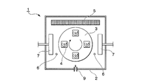
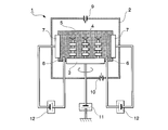
- the conventional coated tool for example, as shown in FIGS.
- the tool base is loaded into an arc ion plating apparatus which is a kind of physical vapor deposition apparatus, and the tool base is set to 500 with a heater. While being heated to a temperature of 0 ° C., an arc discharge is generated between the anode electrode and the cathode electrode on which an Al—Cr alloy having a predetermined composition is set under the condition of current: 90 A, and at the same time, nitrogen as a reaction gas in the apparatus A gas is introduced to form a reaction atmosphere of 2 Pa.
- the (Al, Cr) N layer is deposited on the surface of the tool base under the condition that a bias voltage of ⁇ 100 V is applied to the tool base. It is also known that it can be manufactured.
- Patent Document 2 discloses that the coating layer is made of columnar crystals as a coating tool that improves chipping resistance by suppressing chipping of the coating layer on the rake face and improves wear resistance on the flank face.
- the coating layer thickness at the rake face is smaller than the coating layer thickness at the flank face, and the average crystal width of the upper layer region on the coating layer surface side is larger than the average crystal width of the lower layer region on the coating layer substrate side.
- the ratio of the thickness of the upper layer region to the coating layer thickness at the rake face is smaller than the ratio of the thickness of the upper layer region to the coating layer thickness at the flank face, and the average crystal width of the columnar crystals at the rake face Describes a coated tool (end mill) that is smaller than the average crystal width of the columnar crystals at the flank face.
- the film formed on the substrate is: A first coating layer, the first coating layer includes a microstructure region and a coarse tissue region, and the microstructure region has an average crystal grain size of a compound constituting it of 10 to 200 nm; and An average compressive stress that occupies a range of 50% or more of the total thickness of the first coating layer from the surface side of the first coating layer and is a stress in a range of ⁇ 4 GPa to ⁇ 2 GPa
- the first coating layer has a stress distribution in its thickness direction, and has two or more maximum values or minimum values in the stress distribution, and these maximum values or minimum values are the thickness direction surface. Coated tools with higher compressive stress are recorded on the side. It is.
- Japanese Patent No. 3969230 B
- Japanese Unexamined Patent Publication No. 2008-296290 A
- Japanese Unexamined Patent Publication No. 2011-67883 A
- the conventional coated tool can improve chipping resistance, chipping resistance, and wear resistance to some extent, but if it is used for more severe cutting such as carbon steel and alloy steel, chipping will not occur. It is easy to occur or wear and wear increase, and this causes the service life in a relatively short time.
- the present inventors are excellent in wear resistance as well as chipping resistance in cutting of carbon steel, alloy steel, etc., in order to provide a coated tool that exhibits excellent cutting performance over a long period of use.
- the following knowledge was obtained.
- a CVD method As a means for forming a hard coating layer, a CVD method, a PVD method, or the like is generally employed as a means for forming a coated tool.
- a PVD method an arc ion plating method (hereinafter referred to as a PVD method)
- the hard coating layer made of (Al, Cr) N is formed by the AIP method)
- the tool base is inserted into the apparatus and a predetermined bias voltage is applied.
- an arc discharge is generated between the anode electrode and an Al—Cr alloy target having a predetermined composition while the inside of the apparatus is heated to a predetermined temperature, and at the same time, nitrogen gas is introduced into the apparatus as a reactive gas, A hard coating layer was formed by vapor deposition in the reaction atmosphere (see FIGS. 1A and 1B).
- the inventors applied a magnetic field between the tool base and the target when forming the hard coating layer made of (Al, Cr) N by the conventional AIP method, and measured the influence of the magnetic field on the structure of the hard coating layer. I examined it. As a result, the following was found.
- the hard coating layer by the AIP method in a magnetic field having a predetermined strength, the crystal grain size of the granular crystal grains constituting the hard coating layer can be adjusted. Moreover, the value of the residual stress formed in the hard coating layer can be controlled. Furthermore, the crack occupation rate of the continuous crack formed in the corner part of a cutting-blade front-end
- the coated tool provided with the hard coating layer made of (Al, Cr) N in which the crystal grain size, the residual stress value and the crack occupancy of the hard coating layer are optimized in this way is carbon steel, alloy steel, etc. Excellent cutting resistance and wear resistance in cutting. As a result, this coated tool exhibits excellent cutting performance over a long period of use.
- the present invention has been made based on the above findings and has the following aspects.
- a surface-coated cutting tool in which a hard coating layer having an average layer thickness of 2 to 10 ⁇ m is vapor-deposited on the surface of a tool base composed of a tungsten carbide-based cemented carbide,
- the hard coating layer is composed of a composite nitride layer of Al and Cr, and the content ratio of Cr in the total amount of Al and Cr is 0.2 to 0.5 (however, the atomic ratio)
- the layer has a granular crystal structure, and the average grain size of the granular crystal grains on the surface of the hard coating layer formed on the region is 0.2 to 0.5 ⁇ m.
- the average grain size of the granular crystal grains at the interface of the coating layer is 0.02 to 0.1 ⁇ m smaller than the average grain size of the granular crystal grains on the surface of the hard coating layer, and the grain size is 0.15 ⁇ m or less.
- a surface-coated cutting tool wherein the crystal grain length ratio is 20% or less.
- the tool base is supported so that a part or all of the flank of the tool base and the surface of the target on the tool base side are horizontal when the tool base is manufactured.
- Method. (6) The method for producing a surface-coated cutting tool according to (5), wherein the magnetic field is 140 to 400 mT ⁇ mm as an integrated magnetic force.
- the coated tool according to one aspect of the present invention has a hard coating layer composed of an (Al, Cr) N layer having a predetermined composition in a range up to a position 100 ⁇ m away from the blade edge. Consisting of a granular crystal structure, the surface particle size is 0.2 to 0.5 ⁇ m, the interface particle size is 0.02 to 0.1 ⁇ m smaller than the surface particle size, and 100 ⁇ m from the cutting edge on the flank face In the range up to the distant position, the crystal grain length ratio occupied by crystal grains having a grain size of 0.15 ⁇ m or less is 20% or less, and the compressive residual stress in the hard coating layer is 2.0 to 2.7 GPa. Because the crack occupancy ratio ⁇ / ⁇ of the cutting edge is 0.3 to 1.0, it exhibits excellent chipping resistance and wear resistance in cutting of carbon steel, alloy steel, etc. Excellent cutting performance over use.
- the schematic explanatory drawing of the conventional AIP apparatus is shown, and the top view is shown.
- the schematic explanatory drawing of the conventional AIP apparatus is shown, and the side view is shown.
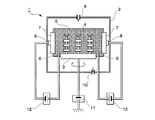
- the schematic explanatory drawing of the AIP apparatus for producing the covering tool of this invention is shown, (The top view is shown.
- the schematic explanatory drawing of the AIP apparatus for producing the covering tool of this invention is shown, and the side view is shown.
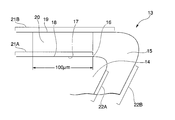
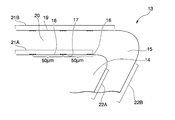
- the longitudinal cross-section schematic explanatory drawing of the coated tool of 1 aspect of this invention is shown.
- FIG. 3A is a schematic explanatory view of a longitudinal section of a coated tool of one embodiment of the present invention.
- a hard coating layer 15 is formed on a base 14.
- a cutting edge portion is formed between the flank 21 and the rake face 22 of the covering tool 13.
- the hard coating layer 15 of the coated tool 13 of the present invention is composed of a composite nitride layer ((Al, Cr) N layer) of Al and Cr.
- the Al component improves the high temperature hardness and heat resistance
- the Cr component improves the high temperature strength
- the high temperature oxidation resistance is improved by the coexistence of Cr and Al. It is already well known as a hard coating layer having excellent hardness, heat resistance, high temperature strength and high temperature oxidation resistance. If the content ratio of Cr in the total amount with Al (atomic ratio, the same applies hereinafter) is less than 0.2, it is difficult to ensure high temperature strength at the time of cutting, while Cr accounts for the total amount with Al. When the content ratio (atomic ratio) exceeds 0.5, the Al content ratio is relatively reduced, leading to a decrease in high-temperature hardness and a decrease in heat resistance.
- the Cr content (atomic ratio) in the total amount with Al is 0.2 to 0.5.
- a more preferable Cr content is 0.22 to 0.45.
- An even more preferable Cr content is 0.25 to 0.42.
- the average thickness of the hard coating layer made of the (Al, Cr) N layer is less than 2 ⁇ m, excellent wear resistance cannot be exhibited over a long period of time, resulting in a short tool life.
- the average layer thickness exceeds 10 ⁇ m, chipping tends to occur at the blade edge portion.
- the average layer thickness of the hard coating layer 15 in the coated tool 13 of the present invention is 2 to 10 ⁇ m.
- the average layer thickness of the hard coating layer 15 is more preferably 2.5-9.
- An even more preferred average layer thickness is 3-8.
- (B) Layer structure of hard coating layer composed of (Al, Cr) N layer In the coated tool 13 of the present invention, the compressive residual stress in the hard coating layer is reduced by forming a hard coating layer having more special properties in a specific region of the flank 21.
- the above flank specific area is a region 17 from the blade edge 16 on the flank surface to a position 100 ⁇ m away from the flank blade edge 16 toward the opposite side on the flank surface.
- the hard coating layer 20 formed on the region 17 has the characteristics described below.
- the hard coating layer 20 made of the (Al, Cr) N layer is formed as a granular crystal.
- the average crystal grain size (hereinafter simply referred to as “surface grain size”) of the crystal grains on the surface 19 of the hard coating layer 20 is set to 0.2 to 0.5 ⁇ m.
- the average crystal grain size of the hard coating layer 20 at the interface 18 between the tool base 14 and the hard coating layer 20 (hereinafter, simply referred to as “interface grain size”) is 0.02 to 0.
- the film is formed with a value 1 ⁇ m smaller. That is, on this region 17, the crystal structure of the hard coating layer 20 is formed such that the surface grain size and the interface grain size are in different average crystal grain size ranges. Thereby, it forms into a film so that the compression residual stress formed in a hard coating layer may become in a predetermined numerical range.
- the crystal grains of the hard coating layer at the interface between the tool base and the hard coating layer means the inside of the hard coating layer having a thickness of 0.5 ⁇ m from the interface between the tool base 14 and the hard coating layer 20 in the hard coating layer. It means crystal grains formed in the region.
- crystal grains on the surface of the hard coating layer means crystal grains formed in a region having a depth of 0.5 ⁇ m from the surface of the hard coating layer 20.
- the term “granular crystal” used herein is a term used to distinguish from “columnar crystal”, and specifically means that the aspect ratio of the crystal grain is 1 or more and 6 or less. . The aspect ratio is calculated as the ratio of the longest diameter (long side) to the diameter (short side) perpendicular to the crystal grain cross section, with the long side as the numerator and the short side as the denominator.
- the average crystal grain size will be specifically described as follows.
- the average crystal grain size (surface grain size) of the crystal grains on the hard coating layer surface 19 is less than 0.2 ⁇ m, the compressive residual stress in the hard coating layer increases, so that chipping is likely to occur during cutting.
- the surface particle diameter exceeds 0.5 ⁇ m, the compressive residual stress is reduced, so that the amount of wear during cutting increases, and sufficient wear resistance cannot be exhibited over a long period of use. From the above, the surface particle size of the hard coating layer 20 in the coated tool 13 of the present invention is determined to be 0.2 to 0.5 ⁇ m.
- the average crystal grain size (interface grain size) of the crystal grains of the hard coating layer 20 at the interface 18 between the tool base 14 and the hard coating layer 20 should be a value smaller by 0.02 to 0.1 ⁇ m than the surface grain size. is required.
- the technical reason is that when the interface particle size is smaller than 0.1 ⁇ m from the surface particle size, the difference between the surface particle size and the interface particle size becomes large, and the compressive residual stress in each part The difference increases and the entire film becomes brittle. Therefore, wear and chipping are likely to occur during cutting, resulting in a problem that the cutting performance deteriorates.
- the difference between the interface particle size and the surface particle size is within 0.02 ⁇ m, the difference in compressive residual stress between the surface and the interface becomes the same, and the effect of improving the wear resistance when cutting is performed. Because it cannot be granted.
- the interface particle size is set to a value smaller by 0.02 to 0.1 ⁇ m than the surface particle size, the compressive residual stress on the interface side is increased to such an extent that the entire film does not become brittle.
- the particle size measurement method is described below with reference to FIG. 3B. A section on the flank side is cut out from the tool base blade edge, and the section is observed with an SEM.
- a straight line is drawn parallel to the tool substrate surface, and the distance between crystal grain boundaries is defined as the grain size.
- the position where a straight line is drawn parallel to the surface of the tool base is the position where the longest crystal grain size is obtained in each crystal grain.
- the crystal grain size is measured in a region 17 from the cutting edge 16 on the flank to a position 100 ⁇ m away, and the average value of the average crystal grain size is defined as the surface grain size. More specifically, the edge 16 on the flank and the position on the flank at a position 50 ⁇ m away from the edge and 100 ⁇ m away from the edge within a range of 10 ⁇ m wide (in FIG.
- the interface grain size is calculated by the same method for each crystal grain formed in a region having a thickness of 0.5 ⁇ m from the interface 18 between the tool base 14 and the hard coating layer 20 in the hard coating layer.
- a region 17 up to a position 100 ⁇ m away from the cutting edge 16 on the flank (specifically, the blade edge on the flank and the position on the flank 50 ⁇ m away from the cutting edge and 100 ⁇ m away from the cutting edge)
- the crystal grain length ratio occupied by crystal grains having a grain size of 0.15 ⁇ m or less is required to be 20% or less for both the surface grain size and the interface grain size. This is because when the fine crystal grains having a grain size of 0.15 ⁇ m or less are formed in excess of 20%, the compressive residual stress in the hard coating layer is increased and chipping is likely to occur.
- the ratio of the crystal grain length occupied by crystal grains having a grain size of 0.15 ⁇ m or less means that the grain diameter of a plurality of crystal grains is measured, and the grain diameter is 0.15 ⁇ m relative to the sum of all the measured crystal grain lengths. The ratio of the sum of the following crystal grain lengths is shown.
- the “blade tip” is “the portion closest to the tip of the linear cutting blade excluding the conical portion of the corner portion at the tip of the cutting blade”. This is defined in the present invention.
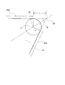
- 3C is a longitudinal cross-sectional schematic explanatory diagram of the coated tool of one embodiment of the present invention, and is a diagram illustrating the positional relationship between the intersection of the virtual extension line of the base flank and the base rake face and the cutting edge on the flank. .
- FIG. 3C only the substrate is shown and the hard coating layer is not shown.
- the distance L ( ⁇ m) between the intersection 23 of the virtual extension line of the base flank 21 and the base rake face 22 and the cutting edge 16 on the flank has the following relationship.
- the (Al, Cr) N layer having the layer structure (b) is formed as the hard coating layer 20 on the region 17 so that the hard coating layer has a thickness of 2.0 to 2.7 GPa.
- compressive residual stress If the value of the compressive residual stress is less than 2.0 GPa, improvement in wear resistance cannot be expected. On the other hand, if this value exceeds 2.7 GPa, chipping is likely to occur.
- the value of the compressive residual stress in the hard coating layer is desirably set to 2.0 to 2.7 GPa.
- the cutting edge angle of the coated tool is ⁇ degrees, and continuous cracks formed in the hard coating layer within the angle range of the ⁇ degrees.
- the crack occupying ratio ⁇ / ⁇ at the corner portion at the tip of the cutting edge is preferably 0.3 to 1.0, and ⁇ / ⁇ is preferably 0.3 to 0.9. It is more preferable that The reason is as follows.
- the crack in this invention means the crack formed in the hard coating layer containing the corner part of a cutting-blade front-end
- the crack in the present invention means a crack having a width of 30 nm or more. The point where the width of the crack tapers at the end and the width of the crack is less than 30 nm is defined as the end of the crack.
- the crack occupation ratio is defined as follows in the present invention. As shown in FIGS.
- the value of (occupation angle ⁇ of continuous crack) / (blade edge angle ⁇ ) is defined as the crack occupancy rate.
- the average layer thickness of the hard coating layer composed of the (Al, Cr) N layer is 2 to 10 ⁇ m, and the content ratio of Cr in the total amount of Al and Cr is 0.2 to 0.5 ( However, the atomic ratio), the surface grain size of the granular crystal grains, and the interface grain size are set in specific numerical ranges, and the grain size in the region 17 up to a position 100 ⁇ m away from the cutting edge 16 on the flank is 0.15 ⁇ m or less.
- the value of the compressive residual stress in the hard coating layer is 2.0 to 2.7 GPa, and the crack occupation ratio ⁇ / ⁇ of the blade edge is A coated cutting tool having a thickness of 0.3 to 1 can be produced efficiently.
- the hard coating layer of the present invention uses an arc ion plating apparatus (AIP apparatus) as shown in FIGS. 2A and 2B, and maintains the temperature of the tool base at 370 to 450 ° C.
- AIP apparatus arc ion plating apparatus
- the tool base is rotated and revolved in the AIP apparatus, and is deposited by applying a predetermined magnetic field (integrated magnetic force 140 to 400 mT ⁇ mm) between the center of the target surface and the tool base closest to the target. can do.
- a cathode electrode made of a Ti electrode for substrate cleaning is provided on one side of the AIP apparatus, and a target (cathode electrode) made of an Al—Cr alloy is provided on the other side.
- the Al content in this Al—Cr alloy is preferably 55 at% Al to 78 at% Al.
- the Cr content is preferably 22 at% Cr to 45 at% Cr corresponding to the Al content.
- a target (cathode electrode) made of a 70 at% Al-30 at% Cr alloy is provided.
- a tool substrate made of tungsten carbide (WC) -based cemented carbide is cleaned and dried, mounted on a rotary table in an AIP apparatus, and 100 A between the Ti electrode and the anode electrode for cleaning the substrate in vacuum.
- An arc discharge is generated to bombard the surface of the tool base while applying a bias voltage of ⁇ 1000 V to the tool base.
- a magnetic field having an integrated magnetic force of 140 to 400 mT ⁇ mm from the center of the surface of the Al—Cr alloy target to the tool base closest to the target is applied.
- nitrogen gas is introduced into the apparatus as a reaction gas.
- the atmospheric pressure in the apparatus is maintained in the range of 9.0 Pa to 9.6 Pa.
- the atmospheric pressure is set to 9.3 Pa.
- a 100 A arc discharge is generated between the Al—Cr alloy target (cathode electrode) and the anode electrode.
- the hard coating layer can be formed by vapor deposition.
- the application of the magnetic field between the Al—Cr alloy target and the tool base is performed by, for example, installing an electromagnetic coil or permanent magnet as a magnetic field generation source around the cathode, or by permanent attachment in the center of the AIP device.
- the magnetic field can be formed by any means such as disposing a magnet.
- medium coarse WC powder having an average particle diameter of 5.5 ⁇ m, fine WC powder of 0.8 ⁇ m, TaC powder of 1.3 ⁇ m, NbC powder of 1.2 ⁇ m, ZrC of 1.2 ⁇ m Powder, 2.3 ⁇ m Cr 3 C 2 powder, 1.5 ⁇ m VC powder, 1.0 ⁇ m (Ti, W) C [by mass ratio, TiC / WC 50/50] powder, and 1 Co powder of 8 ⁇ m was prepared.
- Each of these raw material powders was blended in the blending composition shown in Table 5, further added with wax, mixed in a ball mill for 24 hours in acetone, and dried under reduced pressure.
- the diameter x length of the cutting edge portion is 6 mm x 13 mm, and it is made of a WC-based cemented carbide having a two-blade ball shape with a twist angle of 30 degrees.
- Tool bases (end mills) 1 to 3 and tool bases (end mills) 4 and 5 made of a WC-based cemented carbide having a two-blade square shape with a diameter ⁇ length of the cutting edge portion of 10 mm ⁇ 22 mm. Each was manufactured.
- Each of the tool bases 1 to 5 is ultrasonically cleaned in acetone and dried, and is separated from the central axis on the rotary table of the AIP apparatus shown in FIGS. 2A and 2B by a predetermined distance in the radial direction. Attached along the outer periphery at the position. A Ti cathode electrode for bombard cleaning was placed on one side of the AIP apparatus, and a target (cathode electrode) made of a 70 at% Al-30 at% Cr alloy was placed on the other side. (B) Next, the tool base is heated to 400 ° C. with a heater while the apparatus is evacuated and kept in vacuum, and then a DC bias voltage of ⁇ 1000 V is applied to the tool base that rotates while rotating on the rotary table.
- Comparative Example 1 For the purpose of comparison, the condition of (c) in Example 1 was changed (that is, the integrated magnetic force from the center of the surface of the Al—Cr alloy target to the tool substrate was less than 140 mT ⁇ mm, or more than 400 mT ⁇ mm). Further, the surface of the comparative coated tool was changed under the same conditions as in Example 1 except that the condition of (d) was changed (that is, the tool base was maintained at a temperature lower than 370 ° C. or higher than 450 ° C.). Coated end mills 1 to 5 (hereinafter referred to as Comparative Examples 1 to 5) were produced.
- the crystal grain morphology of the hard coating layer in the longitudinal section was observed, and both were composed of a granular crystal structure having an aspect ratio of 1 or more and 6 or less. It was.
- the aspect ratio is calculated as the ratio of the length of the longest diameter (long side) to the diameter (short side) perpendicular to the crystal grain cross section, with the long side as the numerator and the short side as the denominator.
- the crystal grain size of the granular crystal was measured with a scanning electron microscope (SEM), and the surface grain size and the interface grain size in the region up to a position 100 ⁇ m away from the cutting edge on the flank were obtained.
- the average grain size of crystals existing within a range of 10 ⁇ m in width at the three positions of the cutting edge on the flank, the position 50 ⁇ m away from the cutting edge, and the position 100 ⁇ m away from the cutting edge on the flank It calculated and calculated
- the crystal grain size ratio occupied by the crystal grains having a grain size of 0.15 ⁇ m or less is set to the cutting edge on the flank and the flank.
- Tables 2 and 3 show the values measured and calculated above.
- the measurement method of the crystal grain size and the measurement method of the crystal grain size length ratio occupied by crystal grains having a grain size of 0.15 ⁇ m or less are as follows. After polishing the cross section of the flank, including the corner at the tip of the coated tool, the cross section is observed with an SEM image. As measurement conditions, an observation magnification of 10000 times and an acceleration voltage of 3 kV were used. Each crystal grain formed in a region having a depth of 0.5 ⁇ m from the surface of the hard coating layer is used, a straight line is drawn parallel to the tool base surface, and the distance between crystal grain boundaries is defined as the grain size. The position where a straight line is drawn parallel to the surface of the tool base is the position where the longest crystal grain size is obtained in each crystal grain.
- the area from the cutting edge on the flank to the position 100 ⁇ m away, and specific measurement points include the cutting edge on the flank, the position on the flank 50 ⁇ m away from the cutting edge, and the position 100 ⁇ m away from the cutting edge. Then, the crystal grain size of the crystals existing within the range of 10 ⁇ m in width was measured, and the average value of the average crystal grain sizes at the three locations was defined as the surface grain size. In measuring a particle diameter of 10 ⁇ m in width, measurement data of 5 ⁇ m on the blade edge side and 5 ⁇ m on the opposite side to the blade edge were used centering on each measurement point.
- the measurement was performed within a range of 10 ⁇ m in width of 5 ⁇ m on the side of the cutting edge and 5 ⁇ m on the opposite side to the cutting edge, with a position 5 ⁇ m away from the cutting edge.
- the interface grain size was calculated in the same manner for each crystal grain formed in a region having a thickness of 0.5 ⁇ m from the interface between the tool base and the hard coating layer in the hard coating layer.
- the measuring method of the crystal grain size length ratio occupied by crystal grains having a grain size of 0.15 ⁇ m or less is obtained by measuring all the measurement data of the crystal grain sizes measured at the three interfaces and the three surfaces where the above-mentioned particle size was measured. Use.
- the sum of the crystal grain sizes with a grain size of 0.15 ⁇ m or less relative to the sum of the total crystal grain sizes measured was defined as the ratio of the crystal grain length occupied by the crystal grains with a grain size of 0.15 ⁇ m or less.
- the value of the compressive residual stress in the hard coating layer was calculated by using the peak of the AlCrN (420) plane by the 2 ⁇ -sin 2 ⁇ method using X-ray diffraction.
- Tables 2 and 3 show the compressive residual stress values measured above.
- the cutting edge angle ⁇ of the present inventions 1 to 7 and Comparative Examples 1 to 10 was measured, and the occupying angle ⁇ of the continuous crack in the hard coating layer at the corner portion at the tip of the cutting edge was measured. The value of ⁇ was calculated. Tables 2 and 3 show these values. More specifically, the measurement method of the cutting edge angle ⁇ and the occupying angle ⁇ of the continuous crack is as follows. Of the SEM images observed for measuring the crystal grain size, a cross-sectional SEM image of the tip of the cutting edge is used. The measurement conditions used were an observation magnification of 10,000 times and an acceleration voltage of 3 kV.
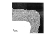
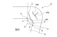
- FIG. 4A shows a cross-sectional SEM image of the tip of the cutting edge according to the third aspect of the present invention, and FIG.
- the cutting edge on the flank is A
- the cutting edge on the rake face is B.
- the perpendicular of the flank passing through A and the perpendicular of the rake face passing through B are drawn, and the intersection of both perpendiculars is set as the center O.
- the blade edge angle ⁇ is an angle formed by AOB.
- the point closest to the perpendicular of the flank passing through A is defined as C
- B Let D be the point closest to the normal of the rake face passing through.
- the occupying angle ⁇ (degrees) of continuous cracks is the angle formed by COD.
- the value calculated by the continuous crack showing the maximum value is defined as the occupation angle ⁇ of the continuous crack.
- the value of (occupation angle ⁇ of continuous crack) / (blade edge angle ⁇ ) is defined as the crack occupancy rate.
- Cutting condition A A groove cutting test of carbon steel under the conditions (referred to as cutting condition A) was performed, and the present inventions 4, 5 and comparative examples 4, 5, 9, 10 were Work material-Plane dimensions: 100mm x 250mm, thickness: 50mm JIS / S55C plate, Rotational speed: 3200 min.
- Cutting condition B Conducted a groove cutting test of carbon steel under the conditions (referred to as cutting condition B), In any groove cutting test, the flank wear width of the cutting edge was measured. The measurement results are shown in Table 4.
- WC powder, TiC powder, ZrC powder, VC powder, TaC powder, NbC powder, Cr 3 C 2 powder, TiN powder, TaN powder, and Co powder all having an average particle diameter of 1 to 3 ⁇ m are prepared as raw material powders. did. These raw material powders were blended into the blending composition shown in Table 1, wet mixed by a ball mill for 72 hours, dried, and then pressed into a green compact at a pressure of 100 MPa. The obtained green compact is sintered in a vacuum of 6 Pa at a temperature of 1400 ° C. for 1 hour. After sintering, the cutting edge portion is subjected to a honing process of R: 0.03 and further subjected to finish polishing. Thus, tool bases 6 to 10 made of WC-base cemented carbide having an ISO standard / SNGA120408 insert shape were formed.
- the surface coating insert of the present invention as the coated tool of the present invention (hereinafter referred to as the present invention 8) (hereinafter referred to as the present invention 8) by forming a hard coating layer comprising an (Al, Cr) N layer having the composition shown in Table 6 and the target average layer thickness. To 14).
- Comparative Example 2 For the purpose of comparison, the tool base (insert) 6-10 was composed of an (Al, Cr) N layer having the composition and target average layer thickness shown in Table 7 under the same conditions as in Comparative Example 1. By forming the hard coating layer, comparative surface coating inserts (hereinafter referred to as Comparative Examples 11 to 20) as comparative coating tools were manufactured.
- the crystal grain morphology of the hard coating layer in the longitudinal section was observed with a scanning electron microscope (SEM). It consisted of the following granular crystal structures.
- SEM scanning electron microscope
- the surface grain size and interface grain size of the crystal grains were determined in the same manner as in the present inventions 1 to 7 and Comparative Examples 1 to 10. Further, grains in a region up to a position 100 ⁇ m away from the cutting edge on the flank (that is, three positions, a cutting edge on the flank and a position 50 ⁇ m away from the cutting edge on the flank and a position 100 ⁇ m away from the cutting edge).
- the crystal grain length ratio occupied by crystal grains having a diameter of 0.15 ⁇ m or less was measured. Furthermore, the value of the compressive residual stress in the hard coating layer was measured. Further, the values of the blade edge angle ⁇ , the occupying angle ⁇ of the continuous crack, and the crack occupying ratio ⁇ / ⁇ were also measured and calculated. Tables 6 and 7 show the values measured and calculated above.
- the coated inserts of the present inventions 8 to 14 and Comparative Examples 11 to 20 are all screwed to the tip of the tool steel tool with a fixing jig, Work material: JIS / SCM440 round bar, Cutting speed: 150 m / min. , Incision: 1.5mm, Feed: 0.3 mm / rev. , Cutting time: 3 minutes
- a dry continuous cutting test of alloy steel (chromium molybdenum steel) under the above conditions (referred to as cutting condition C) was performed, and the flank wear width of the cutting edge was measured. The measurement results are shown in Table 8.
- the coated tool of the present invention determines the surface grain size and interface grain size of the granular crystal grains of the hard coating layer composed of the (Al, Cr) N layer within a specific numerical range, By setting the crystal grain length ratio of the crystal grains having a grain size of 0.15 ⁇ m or less in the region from the cutting edge on the flank to a position of 100 ⁇ m to 20% or less, and compressive residual stress in the hard coating layer By specifying 2.0 to 2.7 GPa, and by defining the crack occupancy rate to 0.3 to 1.0, it has excellent chipping resistance in cutting of carbon steel, alloy steel, etc. Demonstrate wearability. On the other hand, it is apparent that the comparative coated tool in which the structure of the hard coating layer is outside the range defined in the present invention reaches the service life in a relatively short time due to occurrence of chipping or a decrease in wear resistance.
- the coated tool of the present invention exhibits excellent cutting performance over a long period of time when subjected to cutting of carbon steel, alloy steel, etc. It can cope with labor saving, energy saving and cost reduction of processing sufficiently satisfactorily.
Landscapes
- Chemical & Material Sciences (AREA)
- Engineering & Computer Science (AREA)
- Mechanical Engineering (AREA)
- Chemical Kinetics & Catalysis (AREA)
- Materials Engineering (AREA)
- Metallurgy (AREA)
- Organic Chemistry (AREA)
- Cutting Tools, Boring Holders, And Turrets (AREA)
- Physical Vapour Deposition (AREA)
- Drilling Tools (AREA)
- Inorganic Compounds Of Heavy Metals (AREA)
Abstract
Priority Applications (4)
| Application Number | Priority Date | Filing Date | Title |
|---|---|---|---|
| KR1020147025388A KR20140138711A (ko) | 2012-03-05 | 2013-03-05 | 표면 피복 절삭 공구 |
| US14/383,028 US9440293B2 (en) | 2012-03-05 | 2013-03-05 | Surface coating cutting tool |
| EP13757399.4A EP2823920A4 (fr) | 2012-03-05 | 2013-03-05 | Outil de coupe de revêtement de surface |
| CN201380012750.4A CN104169030B (zh) | 2012-03-05 | 2013-03-05 | 表面包覆切削工具 |
Applications Claiming Priority (4)
| Application Number | Priority Date | Filing Date | Title |
|---|---|---|---|
| JP2012047926 | 2012-03-05 | ||
| JP2012-047926 | 2012-03-05 | ||
| JP2013040331A JP5344204B2 (ja) | 2012-03-05 | 2013-03-01 | 表面被覆切削工具 |
| JP2013-040331 | 2013-03-01 |
Publications (1)
| Publication Number | Publication Date |
|---|---|
| WO2013133251A1 true WO2013133251A1 (fr) | 2013-09-12 |
Family
ID=49116726
Family Applications (1)
| Application Number | Title | Priority Date | Filing Date |
|---|---|---|---|
| PCT/JP2013/055924 Ceased WO2013133251A1 (fr) | 2012-03-05 | 2013-03-05 | Outil de coupe de revêtement de surface |
Country Status (6)
| Country | Link |
|---|---|
| US (1) | US9440293B2 (fr) |
| EP (1) | EP2823920A4 (fr) |
| JP (1) | JP5344204B2 (fr) |
| KR (1) | KR20140138711A (fr) |
| CN (1) | CN104169030B (fr) |
| WO (1) | WO2013133251A1 (fr) |
Cited By (1)
| Publication number | Priority date | Publication date | Assignee | Title |
|---|---|---|---|---|
| CN104952971A (zh) * | 2014-03-28 | 2015-09-30 | 三星钻石工业股份有限公司 | 沟槽加工工具及安装有该沟槽加工工具的刻划装置 |
Families Citing this family (19)
| Publication number | Priority date | Publication date | Assignee | Title |
|---|---|---|---|---|
| JP3410803B2 (ja) | 1994-03-09 | 2003-05-26 | 東京電力株式会社 | 発電機の軸ねじり振動抑制制御装置 |
| JP6217216B2 (ja) * | 2013-01-31 | 2017-10-25 | 三菱マテリアル株式会社 | 表面被覆切削工具とその製造方法 |
| JP6090033B2 (ja) * | 2013-03-22 | 2017-03-08 | 三菱マテリアル株式会社 | 表面被覆切削工具 |
| US9903014B2 (en) | 2013-03-22 | 2018-02-27 | Mitsubishi Materials Corporation | Surface-coated cutting tool |
| JP6090034B2 (ja) * | 2013-03-22 | 2017-03-08 | 三菱マテリアル株式会社 | 表面被覆切削工具 |
| JP2015020216A (ja) * | 2013-07-16 | 2015-02-02 | 三菱マテリアル株式会社 | 表面被覆切削工具 |
| EP3106250B1 (fr) * | 2014-03-25 | 2019-07-24 | Kanefusa Kabushiki Kaisha | Outil de coupe |
| JP2016199793A (ja) * | 2015-04-13 | 2016-12-01 | 株式会社神戸製鋼所 | 硬質皮膜 |
| KR102508025B1 (ko) * | 2015-05-11 | 2023-03-10 | 주성엔지니어링(주) | 공정챔버 내부에 배치되는 기판 처리장치 및 그 작동방법 |
| WO2017085975A1 (fr) | 2015-11-16 | 2017-05-26 | 三菱日立ツール株式会社 | Outil de coupe rotatif à bord de coupe remplaçable et plaquette |
| KR102214182B1 (ko) * | 2016-12-26 | 2021-02-09 | 교세라 가부시키가이샤 | 절삭 인서트 |
| CN111032259B (zh) * | 2017-11-16 | 2023-04-07 | 株式会社Moldino | 包覆切削工具及其制造方法和化学气相沉积装置 |
| JP7054473B2 (ja) * | 2018-03-14 | 2022-04-14 | 三菱マテリアル株式会社 | 表面被覆切削工具 |
| CN109158625A (zh) * | 2018-08-14 | 2019-01-08 | 株洲钻石切削刀具股份有限公司 | 一种后刀面具有不同涂层的切削刀片 |
| JP6798534B2 (ja) * | 2018-09-11 | 2020-12-09 | 株式会社タンガロイ | 被覆切削工具 |
| US11103944B2 (en) * | 2019-08-12 | 2021-08-31 | Deere & Company | Self-sharpening cutting tooth for a felling apparatus |
| EP3835018A1 (fr) * | 2019-12-12 | 2021-06-16 | Ceratizit Luxembourg Sàrl | Élément de coupe et son utilisation |
| JP7312382B2 (ja) * | 2021-03-18 | 2023-07-21 | 株式会社タンガロイ | 被覆切削工具 |
| US20240017384A1 (en) * | 2022-07-12 | 2024-01-18 | Milwaukee Electric Tool Corporation | Tool bit |
Citations (6)
| Publication number | Priority date | Publication date | Assignee | Title |
|---|---|---|---|---|
| JP2003165003A (ja) * | 2001-11-28 | 2003-06-10 | Hitachi Tool Engineering Ltd | 硬質皮膜被覆部材 |
| JP2009220260A (ja) * | 2008-02-22 | 2009-10-01 | Hitachi Tool Engineering Ltd | 被覆工具及び被覆工具の製造方法 |
| JP2011067883A (ja) * | 2009-09-24 | 2011-04-07 | Sumitomo Electric Hardmetal Corp | 表面被覆切削工具 |
| JP2011218542A (ja) * | 2010-03-23 | 2011-11-04 | Mitsubishi Materials Corp | 硬質被覆層がすぐれた耐欠損性を発揮する表面被覆切削工具 |
| JP2012024854A (ja) * | 2010-07-20 | 2012-02-09 | Mitsubishi Materials Corp | 表面被覆切削工具 |
| JP2012030346A (ja) * | 2010-07-09 | 2012-02-16 | Mitsubishi Materials Corp | 耐摩耗性と切屑排出性に優れた表面被覆ドリル |
Family Cites Families (10)
| Publication number | Priority date | Publication date | Assignee | Title |
|---|---|---|---|---|
| JP3136778B2 (ja) * | 1992-06-11 | 2001-02-19 | 三菱マテリアル株式会社 | 耐チッピング性にすぐれた表面被覆炭窒化チタン基サーメット製切削工具 |
| JP3700658B2 (ja) | 2002-02-26 | 2005-09-28 | 三菱マテリアル株式会社 | 断続重切削加工で硬質被覆層がすぐれた耐チッピング性を発揮する表面被覆立方晶窒化硼素基焼結材料製切削工具 |
| JP3969230B2 (ja) | 2002-07-24 | 2007-09-05 | 三菱マテリアル株式会社 | 重切削加工条件で硬質被覆層がすぐれた耐チッピング性を発揮する表面被覆超硬合金製切削工具 |
| JP4939032B2 (ja) | 2005-02-08 | 2012-05-23 | 株式会社神戸製鋼所 | 硬質皮膜、および硬質皮膜の製造方法 |
| JP4960149B2 (ja) | 2007-05-29 | 2012-06-27 | 京セラ株式会社 | 表面被覆切削工具 |
| SE533395C2 (sv) * | 2007-06-08 | 2010-09-14 | Sandvik Intellectual Property | Sätt att göra PVD-beläggningar |
| JP5036470B2 (ja) * | 2007-09-27 | 2012-09-26 | 京セラ株式会社 | 表面被覆工具 |
| EP2272080B1 (fr) | 2008-04-28 | 2012-08-01 | CemeCon AG | Dispositif et procede de pretraitement et de revetement de corps |
| JP5344129B2 (ja) * | 2008-10-14 | 2013-11-20 | 三菱マテリアル株式会社 | 硬質被覆層がすぐれた耐摩耗性を発揮する表面被覆切削工具 |
| JP2015020216A (ja) | 2013-07-16 | 2015-02-02 | 三菱マテリアル株式会社 | 表面被覆切削工具 |
-
2013
- 2013-03-01 JP JP2013040331A patent/JP5344204B2/ja active Active
- 2013-03-05 EP EP13757399.4A patent/EP2823920A4/fr not_active Withdrawn
- 2013-03-05 KR KR1020147025388A patent/KR20140138711A/ko not_active Ceased
- 2013-03-05 CN CN201380012750.4A patent/CN104169030B/zh active Active
- 2013-03-05 US US14/383,028 patent/US9440293B2/en active Active
- 2013-03-05 WO PCT/JP2013/055924 patent/WO2013133251A1/fr not_active Ceased
Patent Citations (6)
| Publication number | Priority date | Publication date | Assignee | Title |
|---|---|---|---|---|
| JP2003165003A (ja) * | 2001-11-28 | 2003-06-10 | Hitachi Tool Engineering Ltd | 硬質皮膜被覆部材 |
| JP2009220260A (ja) * | 2008-02-22 | 2009-10-01 | Hitachi Tool Engineering Ltd | 被覆工具及び被覆工具の製造方法 |
| JP2011067883A (ja) * | 2009-09-24 | 2011-04-07 | Sumitomo Electric Hardmetal Corp | 表面被覆切削工具 |
| JP2011218542A (ja) * | 2010-03-23 | 2011-11-04 | Mitsubishi Materials Corp | 硬質被覆層がすぐれた耐欠損性を発揮する表面被覆切削工具 |
| JP2012030346A (ja) * | 2010-07-09 | 2012-02-16 | Mitsubishi Materials Corp | 耐摩耗性と切屑排出性に優れた表面被覆ドリル |
| JP2012024854A (ja) * | 2010-07-20 | 2012-02-09 | Mitsubishi Materials Corp | 表面被覆切削工具 |
Non-Patent Citations (1)
| Title |
|---|
| See also references of EP2823920A4 * |
Cited By (1)
| Publication number | Priority date | Publication date | Assignee | Title |
|---|---|---|---|---|
| CN104952971A (zh) * | 2014-03-28 | 2015-09-30 | 三星钻石工业股份有限公司 | 沟槽加工工具及安装有该沟槽加工工具的刻划装置 |
Also Published As
| Publication number | Publication date |
|---|---|
| JP5344204B2 (ja) | 2013-11-20 |
| KR20140138711A (ko) | 2014-12-04 |
| EP2823920A4 (fr) | 2016-01-06 |
| EP2823920A1 (fr) | 2015-01-14 |
| US20150030401A1 (en) | 2015-01-29 |
| US9440293B2 (en) | 2016-09-13 |
| CN104169030A (zh) | 2014-11-26 |
| JP2013212574A (ja) | 2013-10-17 |
| CN104169030B (zh) | 2017-03-08 |
Similar Documents
| Publication | Publication Date | Title |
|---|---|---|
| JP5344204B2 (ja) | 表面被覆切削工具 | |
| JP6024981B2 (ja) | 高速断続切削加工で硬質被覆層がすぐれた耐チッピング性を発揮する表面被覆切削工具 | |
| JP5099586B2 (ja) | 硬質被覆層がすぐれた耐欠損性を発揮する表面被覆切削工具 | |
| JP5207109B2 (ja) | 硬質被覆層がすぐれた耐欠損性を発揮する表面被覆切削工具 | |
| JP5239292B2 (ja) | 硬質被覆層がすぐれた耐欠損性を発揮する表面被覆切削工具 | |
| JP5850400B2 (ja) | 表面被覆切削工具 | |
| KR102186966B1 (ko) | 표면 피복 절삭 공구 | |
| JP5182501B2 (ja) | 硬質被覆層がすぐれた耐欠損性を発揮する表面被覆切削工具 | |
| JP6102571B2 (ja) | 表面被覆切削工具 | |
| CN103372764B (zh) | 硬质包覆层发挥优异的耐崩刀性的表面包覆切削工具 | |
| JP5239392B2 (ja) | 硬質被覆層がすぐれた耐欠損性を発揮する表面被覆切削工具 | |
| JP4543373B2 (ja) | 非鉄材料の高速切削加工ですぐれた耐摩耗性を発揮する表面被覆超硬合金製切削工具の製造方法 | |
| JP6217216B2 (ja) | 表面被覆切削工具とその製造方法 | |
| JP5850393B2 (ja) | 表面被覆切削工具 | |
| JP5831708B2 (ja) | 表面被覆切削工具 | |
| JP5239296B2 (ja) | 硬質被覆層がすぐれた耐欠損性を発揮する表面被覆切削工具 | |
| JP5682217B2 (ja) | 耐摩耗性と切屑排出性に優れた表面被覆ドリル | |
| JP5099587B2 (ja) | 硬質被覆層がすぐれた耐欠損性を発揮する表面被覆切削工具 | |
| JP2015020216A (ja) | 表面被覆切削工具 | |
| JP2015033758A (ja) | 表面被覆切削工具 | |
| JP5240498B2 (ja) | 硬質被覆層がすぐれた耐欠損性を発揮する表面被覆切削工具 | |
| JP5287019B2 (ja) | 硬質被覆層がすぐれた耐欠損性を発揮する表面被覆切削工具 | |
| JP6090033B2 (ja) | 表面被覆切削工具 | |
| JP6090034B2 (ja) | 表面被覆切削工具 | |
| JP6155940B2 (ja) | 表面被覆切削工具とその製造方法 |
Legal Events
| Date | Code | Title | Description |
|---|---|---|---|
| 121 | Ep: the epo has been informed by wipo that ep was designated in this application |
Ref document number: 13757399 Country of ref document: EP Kind code of ref document: A1 |
|
| WWE | Wipo information: entry into national phase |
Ref document number: 14383028 Country of ref document: US |
|
| NENP | Non-entry into the national phase |
Ref country code: DE |
|
| ENP | Entry into the national phase |
Ref document number: 20147025388 Country of ref document: KR Kind code of ref document: A |
|
| WWE | Wipo information: entry into national phase |
Ref document number: 2013757399 Country of ref document: EP |