WO2013133311A1 - Dispositif de contrôle de pression d'air de pneu - Google Patents
Dispositif de contrôle de pression d'air de pneu Download PDFInfo
- Publication number
- WO2013133311A1 WO2013133311A1 PCT/JP2013/056098 JP2013056098W WO2013133311A1 WO 2013133311 A1 WO2013133311 A1 WO 2013133311A1 JP 2013056098 W JP2013056098 W JP 2013056098W WO 2013133311 A1 WO2013133311 A1 WO 2013133311A1
- Authority
- WO
- WIPO (PCT)
- Prior art keywords
- tire
- wheels
- pressure
- air pressure
- warning lamp
- Prior art date
- Legal status (The legal status is an assumption and is not a legal conclusion. Google has not performed a legal analysis and makes no representation as to the accuracy of the status listed.)
- Ceased
Links
Images

Classifications
-
- B—PERFORMING OPERATIONS; TRANSPORTING
- B60—VEHICLES IN GENERAL
- B60C—VEHICLE TYRES; TYRE INFLATION; TYRE CHANGING; CONNECTING VALVES TO INFLATABLE ELASTIC BODIES IN GENERAL; DEVICES OR ARRANGEMENTS RELATED TO TYRES
- B60C23/00—Devices for measuring, signalling, controlling, or distributing tyre pressure or temperature, specially adapted for mounting on vehicles; Arrangement of tyre inflating devices on vehicles, e.g. of pumps or of tanks; Tyre cooling arrangements
- B60C23/02—Signalling devices actuated by tyre pressure
- B60C23/04—Signalling devices actuated by tyre pressure mounted on the wheel or tyre
- B60C23/0408—Signalling devices actuated by tyre pressure mounted on the wheel or tyre transmitting the signals by non-mechanical means from the wheel or tyre to a vehicle body mounted receiver
- B60C23/0484—Detecting an ongoing tyre inflation
-
- B—PERFORMING OPERATIONS; TRANSPORTING
- B60—VEHICLES IN GENERAL
- B60C—VEHICLE TYRES; TYRE INFLATION; TYRE CHANGING; CONNECTING VALVES TO INFLATABLE ELASTIC BODIES IN GENERAL; DEVICES OR ARRANGEMENTS RELATED TO TYRES
- B60C23/00—Devices for measuring, signalling, controlling, or distributing tyre pressure or temperature, specially adapted for mounting on vehicles; Arrangement of tyre inflating devices on vehicles, e.g. of pumps or of tanks; Tyre cooling arrangements
- B60C23/02—Signalling devices actuated by tyre pressure
- B60C23/04—Signalling devices actuated by tyre pressure mounted on the wheel or tyre
-
- B—PERFORMING OPERATIONS; TRANSPORTING
- B60—VEHICLES IN GENERAL
- B60C—VEHICLE TYRES; TYRE INFLATION; TYRE CHANGING; CONNECTING VALVES TO INFLATABLE ELASTIC BODIES IN GENERAL; DEVICES OR ARRANGEMENTS RELATED TO TYRES
- B60C23/00—Devices for measuring, signalling, controlling, or distributing tyre pressure or temperature, specially adapted for mounting on vehicles; Arrangement of tyre inflating devices on vehicles, e.g. of pumps or of tanks; Tyre cooling arrangements
- B60C23/02—Signalling devices actuated by tyre pressure
- B60C23/04—Signalling devices actuated by tyre pressure mounted on the wheel or tyre
- B60C23/0401—Signalling devices actuated by tyre pressure mounted on the wheel or tyre characterised by the type of alarm
-
- B—PERFORMING OPERATIONS; TRANSPORTING
- B60—VEHICLES IN GENERAL
- B60C—VEHICLE TYRES; TYRE INFLATION; TYRE CHANGING; CONNECTING VALVES TO INFLATABLE ELASTIC BODIES IN GENERAL; DEVICES OR ARRANGEMENTS RELATED TO TYRES
- B60C23/00—Devices for measuring, signalling, controlling, or distributing tyre pressure or temperature, specially adapted for mounting on vehicles; Arrangement of tyre inflating devices on vehicles, e.g. of pumps or of tanks; Tyre cooling arrangements
- B60C23/02—Signalling devices actuated by tyre pressure
- B60C23/04—Signalling devices actuated by tyre pressure mounted on the wheel or tyre
- B60C23/0408—Signalling devices actuated by tyre pressure mounted on the wheel or tyre transmitting the signals by non-mechanical means from the wheel or tyre to a vehicle body mounted receiver
-
- B—PERFORMING OPERATIONS; TRANSPORTING
- B60—VEHICLES IN GENERAL
- B60C—VEHICLE TYRES; TYRE INFLATION; TYRE CHANGING; CONNECTING VALVES TO INFLATABLE ELASTIC BODIES IN GENERAL; DEVICES OR ARRANGEMENTS RELATED TO TYRES
- B60C23/00—Devices for measuring, signalling, controlling, or distributing tyre pressure or temperature, specially adapted for mounting on vehicles; Arrangement of tyre inflating devices on vehicles, e.g. of pumps or of tanks; Tyre cooling arrangements
- B60C23/02—Signalling devices actuated by tyre pressure
- B60C23/04—Signalling devices actuated by tyre pressure mounted on the wheel or tyre
- B60C23/0408—Signalling devices actuated by tyre pressure mounted on the wheel or tyre transmitting the signals by non-mechanical means from the wheel or tyre to a vehicle body mounted receiver
- B60C23/0415—Automatically identifying wheel mounted units, e.g. after replacement or exchange of wheels
- B60C23/0416—Automatically identifying wheel mounted units, e.g. after replacement or exchange of wheels allocating a corresponding wheel position on vehicle, e.g. front/left or rear/right
-
- B—PERFORMING OPERATIONS; TRANSPORTING
- B60—VEHICLES IN GENERAL
- B60C—VEHICLE TYRES; TYRE INFLATION; TYRE CHANGING; CONNECTING VALVES TO INFLATABLE ELASTIC BODIES IN GENERAL; DEVICES OR ARRANGEMENTS RELATED TO TYRES
- B60C23/00—Devices for measuring, signalling, controlling, or distributing tyre pressure or temperature, specially adapted for mounting on vehicles; Arrangement of tyre inflating devices on vehicles, e.g. of pumps or of tanks; Tyre cooling arrangements
- B60C23/02—Signalling devices actuated by tyre pressure
- B60C23/04—Signalling devices actuated by tyre pressure mounted on the wheel or tyre
- B60C23/0486—Signalling devices actuated by tyre pressure mounted on the wheel or tyre comprising additional sensors in the wheel or tyre mounted monitoring device, e.g. movement sensors, microphones or earth magnetic field sensors
- B60C23/0488—Movement sensor, e.g. for sensing angular speed, acceleration or centripetal force
Definitions
- the present invention relates to a tire pressure monitoring device.
- Patent Document 1 discloses a technology that, when the tire air pressure is reduced by a predetermined percentage from the recommended air pressure, turns on a warning lamp to prompt the driver to travel at the recommended air pressure.
- An object of the present invention is a tire capable of preventing a warning lamp from being lit in a tire location when an appropriate pressure adjustment is performed after tire rotation in a front / rear differential pressure vehicle having different recommended tire pressures for front and rear wheels.
- the object is to provide a pneumatic monitoring device.
- the warning lamp is turned off when the vehicle is stopped, the tire pressure of the two wheels is equal to or higher than the higher one of the front wheel side threshold and the rear wheel side threshold, and the remaining When the tire pressure of the two wheels is equal to or greater than the lower value, the warning lamp is kept off regardless of the determination result of the first abnormality determination means.
- the warning lamp When the vehicle is stopped, the warning lamp is turned off, the tire pressure of the two wheels is higher than the higher value of the front wheel side threshold and the rear wheel side threshold, and the tire pressure of the remaining two wheels is lower If the pressure is higher than that, it is highly possible that the air pressure adjustment has been performed after the tire rotation. In this case, the warning lamp can be prevented from being turned on during the tire location by continuing to turn off the warning lamp.
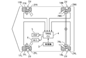
- FIG. 1 is a configuration diagram of a tire air pressure monitoring device of Example 1.
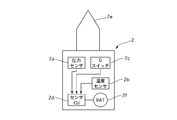
- FIG. 1 is a configuration diagram of a TPMS sensor 2 of Example 1.
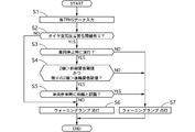
- FIG. It is a flowchart which shows the flow of the warning lamp incorrect lighting prevention control process implemented by TPMSCU4 of Example 1.
- FIG. It is explanatory drawing which shows the incorrect lighting prevention effect of the warning lamp 6 of Example 1.
- FIG. 1 is a configuration diagram of a tire air pressure monitoring device of Example 1.
- FIG. 1 is a configuration diagram of a TPMS sensor 2 of Example 1.
- FIG. It is a flowchart which shows the flow of the warning lamp incorrect lighting prevention control process implemented by TPMSCU4 of Example 1.
- FIG. It is explanatory drawing which shows the incorrect lighting prevention effect of the warning lamp 6 of Example 1.
- FIG. 1 is a configuration diagram of a tire pressure monitoring apparatus according to the first embodiment.
- FL at the end of each symbol indicates a left front wheel
- FR indicates a right front wheel
- RL indicates a left rear wheel
- RR indicates a right rear wheel.
- the description of FL, FR, RL, and RR is omitted when there is no need to explain them individually.
- the tire pressure monitoring device of the first embodiment includes a TPMS (Tire Pressure Monitoring System) sensor 2, a receiver 3, a TPMS control unit (TPMSCU) 4, a display 5, a warning lamp 6, a wheel speed sensor 7, Is provided.
- the TPMS sensor 2 is attached to each wheel 1, and the receiver 3, the TPMSCU 4, the display 5, the warning lamp 6, and the wheel speed sensor are provided on the vehicle body side.
- the TPMS sensor 2 is attached to an air valve (not shown) position of the tire.
- FIG. 2 is a configuration diagram of the TPMS sensor 2 according to the first embodiment.
- the TPMS sensor 2 includes a pressure sensor (air pressure detection means) 2a, a temperature sensor 2b, an acceleration switch (G switch) 2c, a sensor control unit (sensor CU) 2d, a transmitter 2e, and a button battery 2f.
- the pressure sensor 2a detects tire air pressure [kPa].
- the temperature sensor 2b detects the temperature [° C.] of the air in the tire.
- the G switch 2c is a switch that is turned off when the centrifugal acceleration [g] acting on the tire is less than a predetermined value, and turned on when the acceleration is greater than or equal to a predetermined value.
- the sensor CU2d is operated by electric power from the button battery 2f, and includes a tire pressure information detected by the pressure sensor 2a, a temperature information in the tire detected by the temperature sensor 2b, and a TPMS including a sensor ID (identification information). Data is transmitted from the transmitter 2e by radio signal.
- Sensor CU2d uses G switch 2c ON / OFF as a trigger, stops transmission of TPMS data in extremely low vehicle speed range (G switch OFF) including stopping, and TPMS data in higher vehicle speed range (G switch ON) Are transmitted at a predetermined interval (for example, every one minute).
- the receiver 3 receives and decodes the radio signal output from each TPMS sensor 2, and outputs it to the TPMSCU 4.
- TPMSCU4 reads each TPMS data, refers to the correspondence between each sensor ID and each wheel position stored in advance in the internal memory from the sensor ID of the TPMS data, and corresponds to which wheel position the TPMS data corresponds to
- the tire pressure contained in the TPMS data is displayed on the display 5 as the corresponding wheel position air pressure. Further, when the tire air pressure decreases by a predetermined ratio (for example, 20%) or more with respect to the recommended air pressure, the TPMSCU 4 turns on the warning lamp 6 to warn of a decrease in the air pressure and prompts the driver to travel at the appropriate air pressure.
- the recommended air pressure for the front wheels is set to 500 [kPa]
- the recommended air pressure for the rear wheels is set to 300 [kPa].
- the wheel speed sensor 7 is provided corresponding to each wheel, detects the wheel speed of the corresponding wheel, and outputs a wheel speed pulse corresponding to the wheel speed.
- TPMSCU4 calculates the traveling speed (vehicle speed) of the vehicle from each wheel speed pulse.
- Example 1 in order to register the correspondence between each sensor ID and each wheel position after tire rotation by storing and updating in the memory 9, if there is a possibility that tire rotation has been performed, the TPMSCU4 side Autolocation is performed to determine which wheel each TPMS sensor 2 belongs to.
- the TPMSCU 4 determines that the tire rotation may have been performed when the elapsed time from the ignition switch OFF to the ON is equal to or longer than a predetermined time (for example, 15 minutes). TPMSCU4 monitors the tire air pressure of each wheel 1 based on the air pressure information of TPMS data transmitted from each TPMS sensor 2 when the elapsed time from the ignition switch OFF to ON is less than the predetermined time. Is implemented. On the other hand, when the elapsed time from the ignition switch to the ON is equal to or longer than the predetermined time, the “auto location mode” for determining the wheel position of each TPMS sensor 2 is performed. The auto location mode is performed until the wheel positions of all the TPMS sensors 2 are determined.
- a predetermined time for example, 15 minutes.
- the monitor mode is entered.
- a known method such as a method for determining using the strength (radio wave strength, electric field strength) of a radio signal from each TPMS sensor 2 can be used.
- the tire pressure can be monitored from the air pressure information included in the TPMS data. Based on the relationship, the display 5 displays the air pressure and the warning lamp 6 warns of a decrease in air pressure. At this time, in order to prevent the warning lamp 6 from being turned on erroneously, the TPMSCU 4 of Example 1 is in an auto-location from the monitor mode in spite of the proper air pressure adjustment after the tire rotation. When the mode is changed, the warning lamp erroneous lighting prevention control as shown below is performed. In order to realize the warning lamp erroneous lighting prevention control, the TPMSCU 4 stores the lighting state of the warning lamp 6 and the tire air pressure of each wheel and the air temperature in the tire received in the internal memory every time the vehicle stops. .
- FIG. 3 is a flowchart showing the flow of a warning lamp erroneous lighting prevention control process performed by the TPMSCU 4 of the first embodiment.
- step S1 each TPMS data is input and the tire pressure of each wheel is read.
- step S2 the front wheel tire pressure is the front wheel warning threshold (front wheel side threshold, recommended front wheel pressure x 80%) 400 [kPA] or less, or the rear wheel tire pressure is the rear wheel warning threshold (rear It is determined whether the wheel side threshold value is the rear wheel recommended air pressure ⁇ 80%) 240 [kPA]. If YES, the process proceeds to step S3, and if NO, the process proceeds to step S6.
- Step S2 corresponds to first abnormality determination means. In step S3, it is determined whether or not the warning lamp 6 is extinguished when the vehicle is stopped. If YES, the process proceeds to step S4, and if NO, the process proceeds to step S7.
- step S4 it is determined whether or not the tire pressure for the two wheels is higher than the warning threshold value 400 [kPA] for the front wheels, and whether the tire pressure for the remaining two wheels is higher than the warning threshold value 240 [kPA] for the rear wheels. If YES, the process proceeds to step S5. If NO, the process proceeds to step S7. Steps S3 and S4 correspond to second abnormality determination means. In step S5, whether or not the two wheels whose tire pressure is determined to be higher than the warning threshold 400 [kPA] for the front wheels in step S4 is recognized as front wheels when the vehicle is stopped, that is, the previous auto-location mode.
- step S7 it is determined whether or not the wheel position of the transmitter 2d corresponding to the sensor ID of the two wheels is determined to be the front wheel. If YES, the process proceeds to step S7. If NO, the process proceeds to step S6.
- Step S5 corresponds to third abnormality determination means. In step S6, the warning lamp 6 is turned off. In step S7, the warning lamp 6 is turned on.
- the vehicle of the first embodiment is a front / rear differential pressure vehicle in which the recommended air pressure of the front and rear wheels is set to 500 [kPa] and the recommended air pressure of the rear wheels is set to 300 [kPa].
- the warning threshold (recommended air pressure x 80%) is 400 [kPa]
- the warning threshold for the rear wheels is 240 [kPa].
- the sensor IDs of the TPMS sensors 2 of the left front wheel 1FL, the right front wheel 1FR, the left rear wheel 1RL, and the right rear wheel 1RR before tire rotation are A, B, C, and D.
- the tire pressure before tire rotation is the recommended air pressure
- the tire pressure of the left and right front wheels is insufficient for the recommended air pressure of 200 [kPa]
- the driver adjusts each tire air pressure so that it becomes the recommended air pressure (FIG. 4B).
- the warning lamp is turned on until the correspondence between each sensor ID and the wheel position is updated by autolocation. Since the driver adjusts each tire pressure to the recommended pressure, lighting of the warning lamp gives the driver a feeling of strangeness.
- step S3 it is determined in step S3 that the warning lamp is turned off when the vehicle is stopped.
- step S4 the tire pressure of the two wheels is higher than the warning threshold value 400 [kPA] of the front wheels, and the remaining If it is determined that the tire pressure of the two wheels is higher than the warning threshold value 240 [kPA] for the rear wheels, the warning lamp 6 remains off regardless of the determination result of step S2.
- the warning lamp 6 is turned off when the vehicle is stopped, the tire pressure of the two wheels is higher than the warning threshold value 400 [kPA] of the front wheels, and the tire pressure of the remaining two wheels is the warning threshold value 240 [ kPA], that is, the warning lamp 6 is turned off when the vehicle is stopped, the tire pressure of the two wheels is in the vicinity of the recommended pressure of 500 [kPa] for the front wheels, and the tire pressure of the remaining two wheels is If the rear wheel is near the recommended air pressure of 300 [kPa], it is highly possible that the air pressure was adjusted after the tire rotation. In this case, the warning lamp 6 is kept off so that The warning lamp 6 can be prevented from turning on. Therefore, in the case of FIG.
- the warning lamp 6 when the warning lamp 6 is lit when the vehicle is stopped, the warning lamp 6 is lit. In this case, the driver recognizes a decrease in the air pressure, so that the driver does not feel uncomfortable. Even if the warning lamp 6 is lit when the vehicle is stopped, the tire pressure of the two wheels is higher than the warning threshold 400 [kPA] of the front wheels, and the tire pressures of the remaining two wheels are the rear wheels. Higher than the warning threshold of 240 [kPA], that is, the tire pressure of the two wheels is in the vicinity of the recommended air pressure of 500 [kPa] for the front wheels, and the tire pressure of the remaining two wheels is the recommended air pressure of 300 [kPa] for the rear wheels.
- the warning lamp 6 is not lit when it is in the vicinity, the warning lamp 6 is lit before the vehicle stops, and the driver does not adjust the air pressure appropriately for the warning after the vehicle stops. In this case, the warning lamp 6 does not light during the tire location, and the driver cannot be encouraged to drive at the recommended air pressure. In other words, by considering the lighting state of the warning lamp 6 when the vehicle is stopped, the warning lamp is displayed during the tire location when appropriate measures are not taken when the vehicle is stopped against a decrease in air pressure that occurred before the vehicle stopped. 6 can be prevented from turning off, and the driver can be continuously urged to run at the recommended air pressure.
- step S5 when both of the two wheels for which the tire air pressure is determined to be higher than the warning threshold value 400 [kPA] for the front wheels in step S4 are recognized as the front wheels when the vehicle is stopped, If the wheel has a threshold value 400 [kPA] set as the threshold value, the warning lamp 6 is turned on regardless of the determination result of step S4. If the tire pressure is adjusted properly after the tire rotation when the vehicle is stopped, the tire pressure of the left and right front wheels is 500 [kPa] and the tire pressure of the left and right rear wheels is 300 [kPa].
- the two wheels that are judged to be higher than the warning threshold of 400 [kPA], that is, the two wheels that are judged to have a tire pressure near the recommended pressure of 500 [kPa] for the front wheels, are both rear wheels before the tire rotation. It should be recognized as a rear wheel when the vehicle is stopped. Therefore, if the wheel is recognized as the front wheel when the two wheels are stopped, the air pressure is not adjusted properly after the tire rotation. In that case, the warning lamp 6 is lit and recommended to the driver. Driving with air pressure can be encouraged.
- the tire pressure monitoring device of the first embodiment has the following effects.
- Pressure sensor 2a for detecting tire air pressure front wheel air pressure is higher than front wheel warning threshold value 400 [kPa]
- rear wheel tire pressure is higher than rear wheel warning threshold value 240 [kPa]
- the second abnormality determining means S3, S4 for continuing the extinguishing state of the warning lamp 6 is provided.
- the warning lamp 6 When the vehicle is stopped, the warning lamp 6 is turned off, the tire pressure of the two wheels is higher than the warning threshold value 400 [kPA] of the front wheels, and the tire pressure of the remaining two wheels is the warning threshold value 240 [kPA] of the rear wheels. If it is higher, the possibility that the air pressure adjustment was performed after tire rotation is high, so in that case, you can prevent the warning lamp 6 from turning on during the tire location by continuing the extinguishing state of the warning lamp 6. It can prevent the driver from feeling uncomfortable. In addition, if the driver does not take appropriate measures against the drop in air pressure that occurred before the vehicle stopped, the warning lamp 6 can be prevented from turning off during the tire location, and the driver can run at the recommended air pressure. Can be continuously urged.
- the warning lamp 6 When the vehicle is stopped, the warning lamp 6 is turned off, the tire pressure of the two wheels is close to the recommended air pressure of 500 [kPa] for the front wheels, and the tire pressure of the remaining two wheels is the recommended pressure of 300 [kPa] for the rear wheels. If it is in the vicinity, there is a high possibility that the air pressure adjustment was performed after tire rotation, so in that case, you can prevent the warning lamp 6 from turning on during the tire location by continuing the extinguishing state of the warning lamp 6. This can prevent the driver from feeling uncomfortable. In addition, if the driver does not take appropriate measures against the drop in air pressure that occurred before the vehicle stopped, the warning lamp 6 can be prevented from turning off during the tire location, and the driver can run at the recommended air pressure. Can be continuously urged.
- the warning threshold value 400 [kPA] for the front wheels is set as the threshold value when the vehicle is stopped.
- the third abnormality determining means (S5) for turning on the warning lamp 6 regardless of the determination result of the second abnormality determining means is provided. If the tire pressure is adjusted properly after the tire rotation when the vehicle is stopped, the tire pressure of the left and right front wheels is 500 [kPa] and the tire pressure of the left and right rear wheels is 300 [kPa].
- Both of the two wheels determined to be higher than the warning threshold value 400 [kPA] are rear wheels before the tire rotation, and should be recognized as rear wheels when the vehicle is stopped. Therefore, if both wheels are recognized as front wheels when the vehicle is stopped, proper air pressure adjustment is not performed after tire rotation. In that case, the warning lamp 6 is lit to recommend to the driver. Driving with air pressure can be encouraged.
- the second abnormality determining means The third abnormality determining means (S5) for turning on the warning lamp 6 regardless of the determination result is provided. If the tire pressure is adjusted properly after tire rotation when the vehicle is stopped, the tire pressure of the left and right front wheels is 500 [kPa], and the tire pressure of the left and right rear wheels is 300 [kPa].
- the two wheels that are determined to have an air pressure near the recommended air pressure of 500 [kPa] for the front wheels are both rear wheels before the tire rotation, and should be recognized as the rear wheels when the vehicle is stopped. Therefore, if the two wheels are recognized as front wheels when the vehicle is stopped, proper air pressure adjustment has not been performed after tire rotation. Driving can be encouraged.
- the recommended air pressure and the warning threshold are constant, but may be variable according to the air temperature in the tire.
- the recommended air pressure Pwarm during traveling can be expressed as follows using the Boyle-Charles law.
- Pwarm Twarm ⁇ Pcold / Tcold
- Twarm the temperature in the tire during running
- Pcold the placard pressure
- Tcold the temperature in the tire when the driver adjusts the tire air pressure to the placard pressure (when cold).
Landscapes
- Engineering & Computer Science (AREA)
- Mechanical Engineering (AREA)
- Measuring Fluid Pressure (AREA)
Abstract
Priority Applications (4)
| Application Number | Priority Date | Filing Date | Title |
|---|---|---|---|
| CN201380013061.5A CN104159755B (zh) | 2012-03-09 | 2013-03-06 | 轮胎气压监视装置 |
| EP13758591.5A EP2823974B1 (fr) | 2012-03-09 | 2013-03-06 | Dispositif de contrôle de pression d'air de pneu |
| JP2014503874A JP5817914B2 (ja) | 2012-03-09 | 2013-03-06 | タイヤ空気圧モニター装置 |
| US14/372,369 US9227470B2 (en) | 2012-03-09 | 2013-03-06 | Tire pressure monitoring system |
Applications Claiming Priority (4)
| Application Number | Priority Date | Filing Date | Title |
|---|---|---|---|
| JP2012-053814 | 2012-03-09 | ||
| JP2012-053819 | 2012-03-09 | ||
| JP2012053819 | 2012-03-09 | ||
| JP2012053814 | 2012-03-09 |
Publications (1)
| Publication Number | Publication Date |
|---|---|
| WO2013133311A1 true WO2013133311A1 (fr) | 2013-09-12 |
Family
ID=49116784
Family Applications (1)
| Application Number | Title | Priority Date | Filing Date |
|---|---|---|---|
| PCT/JP2013/056098 Ceased WO2013133311A1 (fr) | 2012-03-09 | 2013-03-06 | Dispositif de contrôle de pression d'air de pneu |
Country Status (5)
| Country | Link |
|---|---|
| US (1) | US9227470B2 (fr) |
| EP (1) | EP2823974B1 (fr) |
| JP (1) | JP5817914B2 (fr) |
| CN (1) | CN104159755B (fr) |
| WO (1) | WO2013133311A1 (fr) |
Cited By (2)
| Publication number | Priority date | Publication date | Assignee | Title |
|---|---|---|---|---|
| CN109789742A (zh) * | 2016-10-05 | 2019-05-21 | 株式会社自动网络技术研究所 | 轮胎气压检测系统及车身侧装置 |
| CN119636302A (zh) * | 2024-12-12 | 2025-03-18 | 柳州五菱新能源汽车有限公司 | 一种胎压异常检测方法及装置 |
Families Citing this family (9)
| Publication number | Priority date | Publication date | Assignee | Title |
|---|---|---|---|---|
| WO2014083625A1 (fr) * | 2012-11-28 | 2014-06-05 | トヨタ自動車株式会社 | Dispositif de contrôle de pression pneumatique et procédé de décision de seuil de détermination d'anomalie |
| US9349287B1 (en) * | 2014-09-16 | 2016-05-24 | Live Traffic Data LLC | System for obtaining vehicular traffic flow data from a tire pressure monitoring system |
| JP6120018B2 (ja) * | 2015-01-22 | 2017-04-26 | トヨタ自動車株式会社 | タイヤ空気圧モニタ装置 |
| JP6417248B2 (ja) * | 2015-03-17 | 2018-10-31 | 日立オートモティブシステムズ株式会社 | 車両用制御装置 |
| US10150339B2 (en) * | 2015-04-24 | 2018-12-11 | Advantage Enterprises, Inc. | Systems and methods for monitoring tire pressure |
| CN107505082B (zh) * | 2017-09-01 | 2019-04-02 | 中睿宏智汽车技术(深圳)有限公司 | 胎压标定测量方法 |
| CN107571690B (zh) * | 2017-09-01 | 2018-08-03 | 中睿宏智汽车技术(深圳)有限公司 | 一种基于学习型多元感知的轮胎状态监测方法与装置 |
| US10780749B2 (en) * | 2017-11-21 | 2020-09-22 | Ford Global Technologies, Llc | Systems and methods for vehicle TPMS localization |
| US12397594B2 (en) * | 2023-06-01 | 2025-08-26 | Ford Global Technologies, Llc | Tire pressure monitoring system communication method and system |
Citations (4)
| Publication number | Priority date | Publication date | Assignee | Title |
|---|---|---|---|---|
| JP2004098835A (ja) * | 2002-09-09 | 2004-04-02 | Denso Corp | タイヤ空気圧監視システム |
| JP2007513014A (ja) * | 2003-12-08 | 2007-05-24 | ソシエテ ド テクノロジー ミシュラン | タイヤの膨張方法及びこの方法を実施するための装置及び機械 |
| JP2007176218A (ja) * | 2005-12-27 | 2007-07-12 | Nissan Motor Co Ltd | タイヤ空気圧監視システム |
| JP2008126959A (ja) | 2006-11-24 | 2008-06-05 | Toyota Motor Corp | 車載異常警報装置 |
Family Cites Families (7)
| Publication number | Priority date | Publication date | Assignee | Title |
|---|---|---|---|---|
| JPH03135810A (ja) * | 1989-10-19 | 1991-06-10 | Mitsubishi Motors Corp | タイヤ圧異常検出方法 |
| JP2002082123A (ja) * | 2000-09-11 | 2002-03-22 | Denso Corp | 車輪回転情報検出装置 |
| JP5246077B2 (ja) * | 2009-07-09 | 2013-07-24 | 日産自動車株式会社 | タイヤ空気圧検出装置、タイヤ空気圧監視システムおよびタイヤ空気圧送信方法 |
| JP2011079462A (ja) * | 2009-10-08 | 2011-04-21 | Tokai Rika Co Ltd | タイヤロケーション登録システム及びタイヤロケーション登録方法 |
| JP2011126371A (ja) * | 2009-12-16 | 2011-06-30 | Tokai Rika Co Ltd | タイヤ空気圧監視システム及びタイヤ空気圧検出方法 |
| JP2012140069A (ja) * | 2010-12-28 | 2012-07-26 | Denso Corp | タイヤ空気圧監視装置 |
| DE102011075830A1 (de) * | 2011-05-13 | 2012-11-15 | Bayerische Motoren Werke Aktiengesellschaft | Verfahren zur Echtzeit-Kontrolle des Reifendrucks |
-
2013
- 2013-03-06 US US14/372,369 patent/US9227470B2/en active Active
- 2013-03-06 EP EP13758591.5A patent/EP2823974B1/fr active Active
- 2013-03-06 CN CN201380013061.5A patent/CN104159755B/zh active Active
- 2013-03-06 JP JP2014503874A patent/JP5817914B2/ja active Active
- 2013-03-06 WO PCT/JP2013/056098 patent/WO2013133311A1/fr not_active Ceased
Patent Citations (4)
| Publication number | Priority date | Publication date | Assignee | Title |
|---|---|---|---|---|
| JP2004098835A (ja) * | 2002-09-09 | 2004-04-02 | Denso Corp | タイヤ空気圧監視システム |
| JP2007513014A (ja) * | 2003-12-08 | 2007-05-24 | ソシエテ ド テクノロジー ミシュラン | タイヤの膨張方法及びこの方法を実施するための装置及び機械 |
| JP2007176218A (ja) * | 2005-12-27 | 2007-07-12 | Nissan Motor Co Ltd | タイヤ空気圧監視システム |
| JP2008126959A (ja) | 2006-11-24 | 2008-06-05 | Toyota Motor Corp | 車載異常警報装置 |
Non-Patent Citations (1)
| Title |
|---|
| See also references of EP2823974A4 |
Cited By (2)
| Publication number | Priority date | Publication date | Assignee | Title |
|---|---|---|---|---|
| CN109789742A (zh) * | 2016-10-05 | 2019-05-21 | 株式会社自动网络技术研究所 | 轮胎气压检测系统及车身侧装置 |
| CN119636302A (zh) * | 2024-12-12 | 2025-03-18 | 柳州五菱新能源汽车有限公司 | 一种胎压异常检测方法及装置 |
Also Published As
| Publication number | Publication date |
|---|---|
| CN104159755A (zh) | 2014-11-19 |
| US20140354420A1 (en) | 2014-12-04 |
| US9227470B2 (en) | 2016-01-05 |
| EP2823974A1 (fr) | 2015-01-14 |
| JPWO2013133311A1 (ja) | 2015-07-30 |
| EP2823974A4 (fr) | 2015-03-25 |
| JP5817914B2 (ja) | 2015-11-18 |
| CN104159755B (zh) | 2016-08-24 |
| EP2823974B1 (fr) | 2016-03-02 |
Similar Documents
| Publication | Publication Date | Title |
|---|---|---|
| JP5817914B2 (ja) | タイヤ空気圧モニター装置 | |
| US10576795B2 (en) | Control system, vehicle and method | |
| EP3307568B1 (fr) | Système de commande, véhicule et procédé | |
| US10442254B2 (en) | Controller for a motor vehicle and method | |
| US20180170125A1 (en) | Control system, vehicle and method | |
| US20180304697A1 (en) | Control system, vehicle and method | |
| AU2016275585A1 (en) | Control system, vehicle and method | |
| US20160082791A1 (en) | Method and System for Tire Pressure Monitoring System (TPMS) with Time Encoded Wireless Tire Condition Sensing Device | |
| AU2016275592A1 (en) | Control system, vehicle and method | |
| JP2012140069A (ja) | タイヤ空気圧監視装置 | |
| US9649896B1 (en) | Method and system for tire pressure monitoring system (TPMS) with wireless tire condition sensing and warning | |
| WO2013133308A1 (fr) | Dispositif de contrôle de pression d'air de pneu | |
| GB2539257B (en) | Control system, vehicle and method | |
| KR20130029963A (ko) | 충격 센서를 이용한 tpms 센서 송신 장치 및 그 동작 방법 | |
| JP2019026218A (ja) | タイヤ空気圧モニタリングシステム | |
| JP4747956B2 (ja) | 車輪状態監視装置 | |
| JP5529791B2 (ja) | タイヤ空気圧監視システムの受信機 | |
| JP6273739B2 (ja) | タイヤ空気圧モニター装置 | |
| KR101853762B1 (ko) | 타이어 공기압 모니터링 시스템의 뮤트 경고 제어 장치 및 방법 | |
| JP2018024361A (ja) | 車輪位置検出装置およびそれを備えたタイヤ空気圧監視システム | |
| JP2017154608A (ja) | タイヤ空気圧モニタシステム |
Legal Events
| Date | Code | Title | Description |
|---|---|---|---|
| 121 | Ep: the epo has been informed by wipo that ep was designated in this application |
Ref document number: 13758591 Country of ref document: EP Kind code of ref document: A1 |
|
| ENP | Entry into the national phase |
Ref document number: 2014503874 Country of ref document: JP Kind code of ref document: A |
|
| WWE | Wipo information: entry into national phase |
Ref document number: 2013758591 Country of ref document: EP |
|
| WWE | Wipo information: entry into national phase |
Ref document number: 14372369 Country of ref document: US |
|
| NENP | Non-entry into the national phase |
Ref country code: DE |