WO2013136421A1 - Roue d'automobile - Google Patents
Roue d'automobile Download PDFInfo
- Publication number
- WO2013136421A1 WO2013136421A1 PCT/JP2012/056325 JP2012056325W WO2013136421A1 WO 2013136421 A1 WO2013136421 A1 WO 2013136421A1 JP 2012056325 W JP2012056325 W JP 2012056325W WO 2013136421 A1 WO2013136421 A1 WO 2013136421A1
- Authority
- WO
- WIPO (PCT)
- Prior art keywords
- wheel
- rib
- disk
- disc
- automobile
- Prior art date
- Legal status (The legal status is an assumption and is not a legal conclusion. Google has not performed a legal analysis and makes no representation as to the accuracy of the status listed.)
- Ceased
Links
Images







Classifications
-
- B—PERFORMING OPERATIONS; TRANSPORTING
- B60—VEHICLES IN GENERAL
- B60B—VEHICLE WHEELS; CASTORS; AXLES FOR WHEELS OR CASTORS; INCREASING WHEEL ADHESION
- B60B3/00—Disc wheels, i.e. wheels with load-supporting disc body
- B60B3/12—Means of reinforcing disc bodies
-
- B—PERFORMING OPERATIONS; TRANSPORTING
- B60—VEHICLES IN GENERAL
- B60B—VEHICLE WHEELS; CASTORS; AXLES FOR WHEELS OR CASTORS; INCREASING WHEEL ADHESION
- B60B3/00—Disc wheels, i.e. wheels with load-supporting disc body
- B60B3/04—Disc wheels, i.e. wheels with load-supporting disc body with a single disc body not integral with rim, i.e. disc body and rim being manufactured independently and then permanently attached to each other in a second step, e.g. by welding
- B60B3/041—Disc wheels, i.e. wheels with load-supporting disc body with a single disc body not integral with rim, i.e. disc body and rim being manufactured independently and then permanently attached to each other in a second step, e.g. by welding characterised by the attachment of rim to wheel disc
- B60B3/044—Disc wheels, i.e. wheels with load-supporting disc body with a single disc body not integral with rim, i.e. disc body and rim being manufactured independently and then permanently attached to each other in a second step, e.g. by welding characterised by the attachment of rim to wheel disc characterised by cross-sectional details of the attachment, e.g. the profile
-
- B—PERFORMING OPERATIONS; TRANSPORTING
- B60—VEHICLES IN GENERAL
- B60B—VEHICLE WHEELS; CASTORS; AXLES FOR WHEELS OR CASTORS; INCREASING WHEEL ADHESION
- B60B3/00—Disc wheels, i.e. wheels with load-supporting disc body
- B60B3/04—Disc wheels, i.e. wheels with load-supporting disc body with a single disc body not integral with rim, i.e. disc body and rim being manufactured independently and then permanently attached to each other in a second step, e.g. by welding
- B60B3/041—Disc wheels, i.e. wheels with load-supporting disc body with a single disc body not integral with rim, i.e. disc body and rim being manufactured independently and then permanently attached to each other in a second step, e.g. by welding characterised by the attachment of rim to wheel disc
- B60B3/045—Disc wheels, i.e. wheels with load-supporting disc body with a single disc body not integral with rim, i.e. disc body and rim being manufactured independently and then permanently attached to each other in a second step, e.g. by welding characterised by the attachment of rim to wheel disc characterised by the attachment portions
Definitions
- the present invention relates to an automobile wheel formed by joining a wheel disc and a wheel rim.
- an automobile wheel comprising a wheel disc and a wheel rim is welded by fitting the outer peripheral surface of a disc flange formed on the outer periphery of the wheel disc to the inner peripheral surface of a well portion formed on the wheel rim.
- a disk flange is intermittently formed in the circumferential direction so as to reduce the weight and the amount of material.
- a notch cut out between disk flanges is formed to extend to a hat part of a wheel disk.
- a right-angle surface is formed by bending the plate surface around the opening in the wheel disk at right angles to the wheel radial direction. Accordingly, openings are formed in the wheel disc at predetermined intervals on the outer peripheral side.
- Patent Document 2 the applicant of the present invention, as shown in Patent Document 2, bends the plate surface around the opening in the wheel disk in an oblique manner as an automotive wheel having a notched portion formed between the disk flanges.
- An automotive wheel has been proposed that maintains the desired strength by forming an inclined plane.
- the formation of the opening of the automobile wheel described in Patent Documents 1 and 2 is effective for reducing the weight and reducing the amount of material.
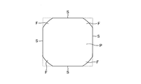
- the disk base material is obtained by cutting four corners of a square steel plate into an arc shape. The corner portion cut into the arc shape is used as a disk flange, and the straight edge connecting the corner portions is the periphery of the opening.
- a mold is not composed of a single metal lump but is composed of a combination of a plurality of mold parts. By doing so, only the mold parts with high wear are periodically replaced in mass production, thereby reducing the running cost of the mold.
- a mold part for bending a flat plate at a right angle such as a mold part for forming a disk flange, is severely worn. Accordingly, in the automobile wheel proposed in Patent Document 1, the wear of the mold parts for forming the right-angled surface is severe, and when the automobile wheel is mass-produced, the frequency of replacing the mold parts increases. Manufacturing cost is high. Further, the automobile wheel proposed in Patent Document 2 has the same problem as that of Patent Document 1.
- the present invention has been made to solve the above-described problems, and an object of the present invention is to provide an automobile wheel that can be manufactured at low cost with few restrictions on interference with a brake device.
- a feature of the present invention is that a wheel flange (10) and a wheel disk (20) are provided, and a disk flange (30) formed intermittently in the circumferential direction on the outer periphery of the wheel disk.
- the wheel rim and the wheel are configured to be joined to the inner peripheral surface of the well portion (11) of the wheel rim, and a part of the notch (31) formed between the adjacent disk flanges is exposed.
- the wheel disk has a rib (40) having a corrugated cross section cut along a plane including the wheel axis along a window edge around the opening.
- a part of the notch formed between adjacent disk flanges is exposed and opened.
- This opening is surrounded by a wheel rim and a wheel disc.
- ribs having a corrugated cross section cut along a plane including the wheel shaft (rotation center axis of the wheel for an automobile) are formed along the window edge around the opening. Therefore, as in the prior art, there is no need to form a right-angle plane obtained by bending the plate surface around the opening at right angles to the wheel radial direction, or an inclined plane obtained by bending the plate surface around the opening obliquely inward.
- a desired strength is obtained by this rib.
- limiting by interference with a brake device can be decreased. Further, the material cost can be reduced and the weight of the automobile wheel can be reduced.
- the rib is formed by the mold (100) for press-molding the hat portion (24) formed around the hub mounting surface (25) of the wheel disc. At the same time, it is to be press-formed in the wheel axial direction.
- the rib is press-formed in the wheel axial direction simultaneously with the forming of the hat portion by a mold (die part) for press-forming the hat portion. Therefore, a special mold (mold part) or the like for forming the rib is not required, and an increase in manufacturing cost can be suppressed.
- the rib is formed into a corrugated plate shape by a recessed recess (41) and protrusions (42, 43) provided on both sides of the recess as viewed from the front or back surface of the wheel disk. That is to be formed.
- the rib is formed in a corrugated plate shape by a concave portion that is recessed when viewed from the surface of the wheel disk and convex portions provided on both sides of the concave portion.
- the inner bending radius (Ri) of the recess is 0.5 mm to 1.0 mm.
- the inner bending radius of the recess is set small, the shape of the recess is easily formed firmly on the window edge of the wheel disc, and the strength of the wheel disc can be ensured. Moreover, since a compact rib can be formed, the restriction
- an outer bending radius (Ro) of the convex portion (41) located on the opening (32) side of the concave portion (41) is 1.3 times or more of the plate thickness of the rib. It is to be 1.6 times.
- the outer bending radius of the convex portion located on the opening side of the concave portion is set smaller, the shape of the convex portion is easily formed firmly on the window edge of the wheel disc, and the strength of the wheel disc is increased. Can be secured.
- the plate thickness of the rib is an average value of the plate thickness in the entire rib.
- Another feature of the present invention is that the axial length in the radial direction connecting the center of the plate thickness from the deepest portion (41a) of the recess (41) at the circumferential center position of the opening to the window edge end face (44) facing the opening.
- the length (L) is 1.5 to 2.0 times the plate thickness t of the rib.
- the window edge of the wheel disk tends to have the lowest strength at the circumferential center position of the opening (the circumferential center position between adjacent disk flanges), but in the present invention, from the deepest part of the recess at the circumferential center position. Since the axial length connecting the plate thickness center to the window edge end face (window edge end face) is set short, the strength of the wheel disk can be secured while suppressing the interference between the wheel disk and the brake device. .
- Another feature of the present invention is that the rib is not formed in a region that fits into the well portion of the disc flange.
- the bonding strength between the disc flange and the well portion is reduced.
- the bonding strength between the disc flange and the well portion is not lowered.
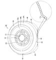
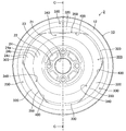
- FIG. 1 is a front view of an automobile wheel according to the first embodiment.
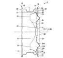
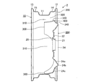
- FIG. 2 is a cross-sectional view taken along the line AA in FIG. 3 is a cross-sectional view taken along the line BB of FIG.
- FIG. 4 is a perspective view of an automobile wheel.
- FIG. 5 is a perspective view of the wheel disc.
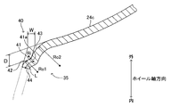
- FIG. 6 is a cross-sectional view of the rib.
- FIG. 7 is an explanatory view showing the deepest position of the rib in the wheel disc.
- FIG. 8 is an explanatory view showing the positional relationship between the fitting area of the disk flange with the wheel well portion and the rib.
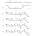
- FIG. 9 is an explanatory diagram showing the processing steps of the wheel disc.
- FIG. 10 is a schematic cross-sectional view of the molding die apparatus.
- FIG. 11 is an enlarged view of a rib forming portion in the molding die apparatus.
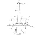
- FIG. 12 is an explanatory diagram for explaining a rotating bending durability test method.
- FIG. 13 is a front view of an automobile wheel according to the second embodiment.
- 14 is a cross-sectional view taken along the line CC of FIG.
- FIG. 15 is an explanatory diagram showing the processing steps of the wheel disk according to the second embodiment.
- FIG. 16 is a cross-sectional view of a rib according to the second embodiment.
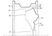
- FIG. 17 is a partial longitudinal sectional view of a vehicle wheel according to a modification.
- FIG. 18 is a cross-sectional view of a rib of a wheel disk and a molding die device according to a modification.
- FIG. 19 is a plan view of the disk substrate according to the first embodiment.
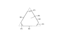
- FIG. 20 is a plan view of a disk substrate according to the second embodiment.
- FIG. 1 is a front view of the automobile wheel as viewed from the front side
- FIG. 2 is a cross-sectional view taken along the line AA in FIG.
- FIG. 2 is a cross-sectional view taken along line BB in FIG.
- FIG. 4 is a perspective view of an automobile wheel
- FIG. 5 is a perspective view of a wheel disk.
- the vehicle wheel 1 is a two-piece type wheel composed of a steel wheel rim 10 and a steel wheel disc 20. As shown in FIG.
- the automobile wheel 1 has a flange 30 (hereinafter referred to as a disc flange 30) of a wheel disc 20 on an inner peripheral surface of a wheel well portion 11 which is a cylindrical portion having the smallest diameter of the wheel rim 10.
- a disc flange 30 is integrally formed by joining to the wheel well portion 11 by various welding such as arc welding, spot welding, laser welding or the like.
- the left side in FIGS. 2 and 3 is the vehicle width direction inner side, that is, the side attached to the hub of the axle, and the right side is the vehicle width direction outer side.
- the outer rim flange 12 and the inner rim flange 13 that support the sidewall portions of the tire are formed at both ends of the wheel rim 10.
- a cylindrical outer bead seat 14 for seating a tire bead is formed on the inner side of the outer rim flange 12 in the vehicle width direction, and a cylindrical shape for seating a tire bead on the outer side of the inner rim flange 13 in the vehicle width direction.
- the inner bead sheet portion 15 is formed.
- a wheel well portion 11 is formed between the outer bead seat portion 14 and the inner bead seat portion 15 for dropping the tire bead when the tire is mounted.
- the rotation center axis of the automobile wheel 1 is referred to as a wheel axis
- the outer direction in the vehicle width direction is referred to as the wheel axis outer direction
- the inner direction in the vehicle width direction is referred to as the wheel axis inner direction
- a direction orthogonal to the wheel axis is referred to as a radial direction
- a direction away from the wheel axis is referred to as an outer radial direction
- a direction approaching the wheel axis is referred to as an inner radial direction.
- a surface having a central portion facing the wheel shaft outward direction is referred to as a front surface
- a surface facing the wheel shaft inward direction is referred to as a back surface
- the wheel disc 20 has a hub hole 21 formed at the center, and a plurality of bolt holes 22 formed around the hub hole 21 at equal intervals on the same circumference. In the present embodiment, four bolt holes 22 are formed. Between adjacent bolt holes 22, convex portions 23 are formed that protrude in the wheel shaft outer direction. An annular hat portion 24 swelled outward in the wheel axis direction is formed on the radially outer side from the arrangement of the bolt holes 22. The back surface of the portion that is radially inward of the hat portion 24 is a hub mounting surface 25 that is connected to the hub of the axle.
- the hat portion 24 is an upwardly inclined portion 24a that is inclined toward the wheel shaft outer direction, a top portion 24b that is formed continuously from the upward inclined portion 24a and protrudes in the wheel shaft outer direction, and a wheel that is formed continuously from the top portion 24b. It is comprised from the downward inclination part 24c which inclines toward the axial direction. The downward inclined portion 24c is bent so that the inclination angle becomes larger during the downward inclination (approaching the wheel axis direction).
- the four disc flanges 30 are formed at a predetermined distance in the circumferential direction in the radially outward direction of the downward inclined portion 24c.
- the four disk flanges 30 are arranged at equal intervals in the circumferential direction, and are formed to extend inward in the wheel axis from the descending inclined portion 24c so as to form a part of a cylinder substantially parallel to the disk axis direction. For this reason, a notch 31 having no base material is formed between the adjacent disk flanges 30.
- Each disk flange 30 is fitted to the inner peripheral surface of the wheel well portion 11 on the tip side.
- the four notches 31 formed between the disk flanges 30 extend to the outer peripheral side of the downward inclined portion 24c of the hat portion 24. Therefore, this notch 31 is exposed to the outside of the automobile wheel 1 to form four openings 32.
- the opening 32 is an area where there is no base material surrounded by the wheel rim 10, the disk flange 30 of the wheel disk 20, and the hat portion 24.
- a portion surrounding the opening 32 is referred to as a window portion 33, and in particular, a window portion on the wheel disc 20 side is referred to as a disc window portion 34.
- a boundary region with the opening 32 in the disk window 34, that is, a peripheral portion of the disk window 34 is referred to as a window edge 35.
- reinforcing ribs 40 are formed in a thin line shape along the window edge 35 in each disk window 34 of the wheel disk 20.
- the center position of the window edge 35 (the intermediate position in the circumferential direction between the adjacent disc flanges 30) is the portion where the strength is the weakest. It is formed over a predetermined length in the circumferential direction with the center position of the window edge 35 as the center.
- FIG. 6 is an enlarged view of a portion where the rib 40 is formed in FIG. 2 (a cross-sectional view cut along a plane including the wheel shaft), and shows a cross-sectional shape of the rib 40 at the center position of the window edge 35. .
- the wheel axis direction is shown in the vertical direction of the drawing.
- the rib 40 is obtained by deforming the front surface and the back surface of the base material in the window edge 35 into a corrugated shape substantially parallel to the concave portion 41 that is linearly depressed along the window edge 35.
- the outer convex portion 42 and the inner convex portion 43 are located on both sides of the concave portion 41.
- the concave portion 41 has an inner bending radius Ri of about 0.5 mm, and the deepest portion 41a is formed in a shape substantially close to a pin angle.
- the outer convex portion 42 located closer to the opening 32 than the concave portion 41 has a curved shape with an outer bending radius Ro1 of 3.3 mm.
- the inner side convex part 43 located in radial direction rather than the recessed part 41 is the curved shape from which the outer side bending radius Ro2 will be 8.0 mm.
- the axial length L in the radial direction connecting the center of the plate thickness from the deepest portion 41a of the recess 41 to the window edge end face 44 facing the opening 32 is set to 4.0 mm.
- the amount of depressions W in the radial direction of the rib 40 is set to 2.0 mm, and the amount of depressions D in the wheel axis direction is set to 4.0 mm.
- the average plate thickness t of the portion where the rib 40 is formed is 2.38 mm.
- the rib 40 is formed along the window edge 35 so that the cross-sectional shape cut along the plane including the wheel axis is corrugated. Moreover, since the deepest part 41a of the recessed part 41 has a shape close to the pin angle, the deepest part 41a appears as one thin line 50 as shown in FIG. Further, as shown in FIG. 8, the circumferential length of the rib 40 is set so that the disc flange 30 is not formed in the area X in which the wheel flange portion 11 is fitted.
- the wheel disk 20 is manufactured by processing a disk substrate P formed by cutting four corners of a substantially square flat steel plate into an arc shape in five steps shown in FIG. Is done.
- the four corner portions F whose outer periphery of the disk base material P is cut in an arc shape are the disk flanges 30, and the circles of the notches 31 formed between the disk flanges 30 are the portions that form the four sides S of the square.
- the right side shows a cross section on the side where the disc flange 30 is formed
- the left side shows a cross section on the side where the disc flange 30 is not formed, that is, the side where the rib 40 is formed.
- a circular recess 51 is formed in the center of the disk base P by press working.
- the nut seat 22a, the convex portion 23, the hat portion 24, and the hub mounting surface 25 are formed by pressing.
- the rib 40 is also formed at the same time.
- FIG. 10 shows an outline of a molding die apparatus 100 used in the second drawing process for molding the rib 40.
- a mold for pressing the disk base material P in the wheel axis direction is shown.
- the right side of the drawing is a mold section on the side where the disk flange 30 is formed
- the left side of the drawing is a mold section on the side where the disk flange 30 is not formed.
- the molding die apparatus 100 includes a lower mold part 110 fixed to a fixing base (not shown), and an upper mold part 120 provided above the lower mold part 110 and movable in the vertical direction.
- the lower mold part 110 is illustrated as if it is made of a single metal lump.
- the lower mold part 110 is actually configured by combining a plurality of mold parts. ing.
- the upper mold part 120 is actually configured by combining a plurality of mold parts.
- the second squeezing step the upper die portion 120 is lowered with the disk base P that has completed the first squeezing step set on the lower die portion 110, so that the space between the upper die portion 120 and the lower die portion 110 is reduced.
- the nut base 22a, the convex portion 23, the hat portion 24, the hub mounting surface 25, and the rib 40 are formed by clamping the disk base material P in the wheel axial direction.
- the portion surrounded by a broken-line circle is a portion for forming the rib 40. An enlarged view of that portion is shown in FIG.
- the upper mold part 120 has a convex part 121 for molding the concave part 41 of the rib 40, an outer concave part 122 for molding the outer convex part 42 and the inner convex part 43 on both sides of the concave part 41, and An inner recess 123 is provided.
- the lower mold part 110 is provided with a concave part 111 for molding the concave part 41 (the convex part when viewed from the back surface) of the rib 40, and the outer convex part 42 and the inner convex part 43 on both sides of the concave part 41.
- An outer convex portion 112 and an inner convex portion 113 are provided.
- the disk base P is in the wheel axial direction between the convex portion 121, the outer concave portion 122, and the inner concave portion 123 of the upper mold portion 120 and the concave portion 111, the outer convex portion 112, and the inner convex portion 113 of the lower mold portion 110.
- the rib 40 is formed into a corrugated plate shape.
- a hub trim process is subsequently performed.
- the hub hole 21 is formed.
- the disk flange 30 is formed by bending the four corner portions F of the disk base material P inward in the disk axis direction so as to be parallel to the disk axis direction. Molded.
- the hub hole flange 21a is formed by bending the plate surface around the hub hole 21 outwardly of the disk axis so as to be parallel to the disk axis direction.
- the bolt hole 22 is formed in the nut seat 22a. In the subsequent coining step, the shape of the bolt hole 22 of the nut seat 22a is adjusted as shown in FIG.
- Wheel size 13 x 4.50B (rim diameter 13 inches, rim width 4.50 inches, flange shape B)
- Disc material: Thickness 2.3 mm, Hot rolled steel plate for automobile structure (SAPH440)
- Rotational bending durability test is performed by applying a constant bending moment to the hub mounting surface of an automobile wheel that rotates at a constant speed.
- the outer rim flange 12 is fixed to the upper surface of the rotary table TB, and the base end LA1 of the load arm LA is connected to the hub mounting surface 25 of the automobile wheel 1.
- the tip end LA2 of the load arm LA is supported so as to be rotatable and radially displaceable.
- the rotary bending endurance test rotates the rotary table TB while applying a load to the tip end LA2 of the load arm LA in the direction of the arrow in the drawing and applying a bending moment to the hub mounting surface 25.
- the rotation speed hereinafter referred to as the durability rotation speed
- the durability rotation speed when an abnormality such as a crack or breakage occurs in the automobile wheel 1 and reaches the durability limit is used as an index of durability.
- the magnitude of the bending moment M was 1.15 kN ⁇ m.
- the durable rotational speed was 250,000 rotations, and the location where the abnormality occurred was in the center in the circumferential direction of the window edge 35, whereas in the automotive wheel 1 of the present embodiment, The durability rotation number was 400,000 rotations, and the location where the abnormality occurred was the hub mounting surface 25. Therefore, it can be seen that the durability of the wheel disk 20 is improved 1.6 times by forming the rib 40.
- the corrugated ribs 40 are formed along the window edge 35, so that the strength of the window edge 35 is increased and the durability of the wheel disc 20 is dramatically improved. Can be improved. Further, the rib 40 is not formed by bending the plate surface around the opening largely inward to form an inclined plane as in the case of the automobile wheel cited as a conventional example, but is formed in a corrugated plate shape. Can be made compact. For this reason, as shown by a two-dot chain line in FIG. 2, it is advantageous for interference with the brake device Br. Further, it is not necessary to increase the width of the disk substrate P, and merits can be obtained in terms of material cost and weight reduction.
- the rib 40 is press-molded simultaneously with the hat portion 24 in the pressing process. For this reason, a dedicated mold part for forming the rib 40 is not required and the manufacturing cost is not increased. Further, the rib 40 is not formed in the area X where the disc flange 30 is fitted to the wheel well portion 11. For this reason, the joint strength between the disk flange 30 and the wheel well portion 11 is not lowered.
- the inner bending radius Ri of the recess 41 is preferably 0.5 mm to 1.0 mm (0.5 mm ⁇ Ri ⁇ 1.0 mm).
- the outer bending radius Ro1 of the outer protrusion 42 is preferably 1.3 to 1.6 times the plate thickness t (1.3t ⁇ Ro1 ⁇ 1.6t).
- the axial length L from the deepest portion 41a of the recess 41 to the window edge end surface 44 is preferably 1.5 to 2.0 times the plate thickness t (1.5t ⁇ L ⁇ 2.0t). .
- the plate thickness t of the rib 40 is an average value of the plate thickness of the entire rib 40.
- FIGS. 13 and 14 show an automobile wheel as a second embodiment, FIG. 13 is a front view of the automobile wheel as viewed from the front side, and FIG. 14 is a sectional view taken along the line CC in FIG. .
- the automobile wheel 2 of the second embodiment is composed of a steel wheel rim 10 and a steel wheel disc 200, and three discs of the wheel disc 200 are arranged on the inner peripheral surface of the wheel well portion 11 of the wheel rim 10.
- the flange 300 is integrally formed by fitting and welding.
- the vehicle wheel 2 according to the second embodiment is different from the vehicle wheel 1 according to the first embodiment only in the number of disk flanges, the number of openings, and the shape of the window portion in the wheel disk 200.
- the point is the same. Accordingly, only the configuration related to the difference will be described here, and the common configuration will be denoted by the same reference numerals as those of the first embodiment, and description thereof will be omitted.
- the wheel disk 20 in the first embodiment is formed by pressing a disk substrate P formed by cutting four corners of a substantially square steel plate into an arc shape, and the wheel in the second embodiment.
- the disk 200 is formed by pressing a disk substrate P1 formed by cutting three corners of a substantially equilateral triangular steel plate with an arc concentric with the center of the equilateral triangle.
- the three corner portions F1 whose outer circumferences are cut in an arc shape are the disk flanges 300
- the portions that are the three sides S1 of the equilateral triangle are the arc-shaped peripheries of the notches 310 formed between the disk flanges 300.
- the three disk flanges 300 are fitted to the inner peripheral surface of the wheel well portion 11 on the tip side.
- the three cutouts 310 formed between the disc flanges 300 extend to a radial intermediate position of the downward inclined portion 24c of the hat portion 24. Therefore, the notch 310 is exposed to the outside of the automobile wheel 2 to form a large opening 320.
- a portion surrounding the opening 320 is a window portion 330.
- the window part on the wheel disk 200 side is called a disk window part 340. Further, the peripheral portion of the disk window 340 is referred to as a window edge 350.
- a reinforcing rib 400 is formed on the wheel disc 200 along the window edge 350.
- the rib 400 is formed into a corrugated plate shape by a concave portion 410 that is linearly narrow along the window edge 350, and an outer convex portion 420 and an inner convex portion 430 that are located on both sides of the concave portion 410. It is formed.
- the rib 400 is formed with the same dimensional relationship (Ri, Ro1, Ro2, L, W, D) as the rib 40 in the first embodiment. Further, the rib 400 is press-molded simultaneously with the nut seat 22a, the convex portion 23, the hat portion 24, and the hub mounting surface 25 by the second drawing step, as in the processing method of the first embodiment (see FIG. 15). .
- the groove-shaped rib whose center is recessed in the wheel shaft inward direction is formed.
- a groove-like rib 500 having a depressed center when viewed from the top may be formed.
- FIG. 17 shows an example applied to the automobile wheel 1 of the first embodiment in which four openings 32 are formed
- the invention can also be applied to the automobile wheel 2 of the second embodiment.
- the rib 500 can be formed in the second drawing step in the same manner as in the above-described embodiment, only by changing the shapes of the lower mold part 110 and the upper mold part 120 in the molding die apparatus 100. it can.
- the rib 500 is formed in a corrugated shape by a convex portion 510 projecting in the wheel axis outward direction, an outer concave portion 520 and an inner concave portion 530 located on both sides of the convex portion 510. Accordingly, when viewed from the rear surface side of the wheel disk 20, the rib 500 is formed in a corrugated shape by the concave portion 511, the outer convex portion 521 and the inner convex portion 531 located on both sides of the concave portion 511.
- the concave portion 511, the outer convex portion 521, and the inner convex portion 531 viewed from the back surface side have substantially the same curved shape as the concave portion 41, the outer convex portion 42, and the inner convex portion 43 viewed from the front surface side of the first embodiment. ing. Further, the axial length L in the radial direction connecting the thickness center from the deepest part 511a of the recess 511 to the window edge end face 44 facing the opening 32 is the same as that in the first embodiment.
- one rib is formed in each disk window, but the number of ribs is not necessarily limited to one, and a plurality of (for example, two) ribs are formed. Also good.
- the cross-sectional shape of the recessed part provided in the center of a rib can be arbitrarily determined, such as U shape, V shape, and a square shape.
- the rib was provided in the wheel disc pressed from the steel plate material.
- the present invention is not limited to this, and a rib may be provided on a wheel disk that has been pressed from a plate material such as aluminum, magnesium alloy, or titanium alloy, and an automobile wheel using these wheel disks may be configured.
Landscapes
- Engineering & Computer Science (AREA)
- Mechanical Engineering (AREA)
- Shaping Metal By Deep-Drawing, Or The Like (AREA)
Priority Applications (2)
| Application Number | Priority Date | Filing Date | Title |
|---|---|---|---|
| PCT/JP2012/056325 WO2013136421A1 (fr) | 2012-03-12 | 2012-03-12 | Roue d'automobile |
| JP2014504495A JP5872023B2 (ja) | 2012-03-12 | 2012-03-12 | 自動車用ホイール |
Applications Claiming Priority (1)
| Application Number | Priority Date | Filing Date | Title |
|---|---|---|---|
| PCT/JP2012/056325 WO2013136421A1 (fr) | 2012-03-12 | 2012-03-12 | Roue d'automobile |
Publications (1)
| Publication Number | Publication Date |
|---|---|
| WO2013136421A1 true WO2013136421A1 (fr) | 2013-09-19 |
Family
ID=49160392
Family Applications (1)
| Application Number | Title | Priority Date | Filing Date |
|---|---|---|---|
| PCT/JP2012/056325 Ceased WO2013136421A1 (fr) | 2012-03-12 | 2012-03-12 | Roue d'automobile |
Country Status (2)
| Country | Link |
|---|---|
| JP (1) | JP5872023B2 (fr) |
| WO (1) | WO2013136421A1 (fr) |
Cited By (3)
| Publication number | Priority date | Publication date | Assignee | Title |
|---|---|---|---|---|
| WO2018138895A1 (fr) * | 2017-01-30 | 2018-08-02 | トピー工業株式会社 | Roue pour véhicule |
| JP2018153858A (ja) * | 2017-03-21 | 2018-10-04 | リンテックス株式会社 | 車両用ホイールディスクの製造方法 |
| CN108778810A (zh) * | 2016-03-18 | 2018-11-09 | 中信戴卡股份有限公司 | 配设有轮毂马达的车轮的混合式轮辋 |
Citations (7)
| Publication number | Priority date | Publication date | Assignee | Title |
|---|---|---|---|---|
| JPS55114601A (en) * | 1979-02-26 | 1980-09-04 | Motor Wheel Corp | Wheel disc and its preparation |
| JPS61211101A (ja) * | 1985-03-07 | 1986-09-19 | モーター・ホイール・コーポレーシヨン | 車輌用車輪 |
| JPH04100701A (ja) * | 1990-08-19 | 1992-04-02 | Bridgestone Corp | 自動車用金属ホイール |
| JPH1081102A (ja) * | 1996-09-09 | 1998-03-31 | Topy Ind Ltd | 自動車用ホイール |
| JP2000168302A (ja) * | 1998-12-07 | 2000-06-20 | Topy Ind Ltd | 自動車用ホイール |
| JP2004182022A (ja) * | 2002-11-29 | 2004-07-02 | Chuo Motor Wheel Co Ltd | 自動車用ホイール |
| JP2005511371A (ja) * | 2001-12-03 | 2005-04-28 | ソシエテ ド テクノロジー ミシュラン | 特に乗用車用のモータ車両ホイールディスク |
-
2012
- 2012-03-12 JP JP2014504495A patent/JP5872023B2/ja not_active Expired - Fee Related
- 2012-03-12 WO PCT/JP2012/056325 patent/WO2013136421A1/fr not_active Ceased
Patent Citations (7)
| Publication number | Priority date | Publication date | Assignee | Title |
|---|---|---|---|---|
| JPS55114601A (en) * | 1979-02-26 | 1980-09-04 | Motor Wheel Corp | Wheel disc and its preparation |
| JPS61211101A (ja) * | 1985-03-07 | 1986-09-19 | モーター・ホイール・コーポレーシヨン | 車輌用車輪 |
| JPH04100701A (ja) * | 1990-08-19 | 1992-04-02 | Bridgestone Corp | 自動車用金属ホイール |
| JPH1081102A (ja) * | 1996-09-09 | 1998-03-31 | Topy Ind Ltd | 自動車用ホイール |
| JP2000168302A (ja) * | 1998-12-07 | 2000-06-20 | Topy Ind Ltd | 自動車用ホイール |
| JP2005511371A (ja) * | 2001-12-03 | 2005-04-28 | ソシエテ ド テクノロジー ミシュラン | 特に乗用車用のモータ車両ホイールディスク |
| JP2004182022A (ja) * | 2002-11-29 | 2004-07-02 | Chuo Motor Wheel Co Ltd | 自動車用ホイール |
Cited By (3)
| Publication number | Priority date | Publication date | Assignee | Title |
|---|---|---|---|---|
| CN108778810A (zh) * | 2016-03-18 | 2018-11-09 | 中信戴卡股份有限公司 | 配设有轮毂马达的车轮的混合式轮辋 |
| WO2018138895A1 (fr) * | 2017-01-30 | 2018-08-02 | トピー工業株式会社 | Roue pour véhicule |
| JP2018153858A (ja) * | 2017-03-21 | 2018-10-04 | リンテックス株式会社 | 車両用ホイールディスクの製造方法 |
Also Published As
| Publication number | Publication date |
|---|---|
| JPWO2013136421A1 (ja) | 2015-08-03 |
| JP5872023B2 (ja) | 2016-03-01 |
Similar Documents
| Publication | Publication Date | Title |
|---|---|---|
| JP3318099B2 (ja) | 不均板厚ディスク | |
| US20100253134A1 (en) | Spoked wheel disk manufacturing method and spoked wheel | |
| CN104245352B (zh) | 机动车用轮盘及其制造方法 | |
| JP4396910B2 (ja) | 自動車車輪用車輪ディスクと自動車車輪を形成する方法 | |
| WO2013160997A1 (fr) | Roue d'automobile | |
| JPWO2012002319A1 (ja) | 車両用ホイール | |
| WO2010107008A1 (fr) | Roue pour automobile | |
| JP5281435B2 (ja) | 自動車用ホイール | |
| WO2012039194A1 (fr) | Roue pour automobile | |
| JP2010115932A (ja) | 自動車用ホイール | |
| JP5872023B2 (ja) | 自動車用ホイール | |
| JP5592945B2 (ja) | 自動車用ホイール | |
| US8770671B2 (en) | Automotive wheel | |
| JP6634481B2 (ja) | 車両用ディスクホイールおよび車両用ホイールディスクの製造方法 | |
| JP4707155B2 (ja) | 車両用ホイール及びその製造方法 | |
| JP5090365B2 (ja) | 自動車用ホイール | |
| JP3996497B2 (ja) | 自動車用ホイール | |
| JP2006082733A (ja) | 自動車用ホイール | |
| JP4270982B2 (ja) | ホイールディスクの製造方法 | |
| JP6244010B2 (ja) | 自動車用ホイールディスク | |
| JP6438153B2 (ja) | ホイールディスクの製造方法、及び、ホイールディスク | |
| CN209037287U (zh) | 车辆用轮 | |
| JP5575551B2 (ja) | 自動車用ホイールディスクの製造方法 | |
| JP2009137391A (ja) | 車両用ホイール | |
| JP5690128B2 (ja) | 自動車用ホイール |
Legal Events
| Date | Code | Title | Description |
|---|---|---|---|
| 121 | Ep: the epo has been informed by wipo that ep was designated in this application |
Ref document number: 12871521 Country of ref document: EP Kind code of ref document: A1 |
|
| ENP | Entry into the national phase |
Ref document number: 2014504495 Country of ref document: JP Kind code of ref document: A |
|
| NENP | Non-entry into the national phase |
Ref country code: DE |
|
| 122 | Ep: pct application non-entry in european phase |
Ref document number: 12871521 Country of ref document: EP Kind code of ref document: A1 |