WO2013136519A1 - Appareil de traitement de signal et appareil de reproduction d'informations - Google Patents
Appareil de traitement de signal et appareil de reproduction d'informations Download PDFInfo
- Publication number
- WO2013136519A1 WO2013136519A1 PCT/JP2012/056918 JP2012056918W WO2013136519A1 WO 2013136519 A1 WO2013136519 A1 WO 2013136519A1 JP 2012056918 W JP2012056918 W JP 2012056918W WO 2013136519 A1 WO2013136519 A1 WO 2013136519A1
- Authority
- WO
- WIPO (PCT)
- Prior art keywords
- signal
- signal processing
- filter
- processing unit
- information recording
- Prior art date
- Legal status (The legal status is an assumption and is not a legal conclusion. Google has not performed a legal analysis and makes no representation as to the accuracy of the status listed.)
- Ceased
Links
Images













Classifications
-
- G—PHYSICS
- G11—INFORMATION STORAGE
- G11B—INFORMATION STORAGE BASED ON RELATIVE MOVEMENT BETWEEN RECORD CARRIER AND TRANSDUCER
- G11B20/00—Signal processing not specific to the method of recording or reproducing; Circuits therefor
- G11B20/10—Digital recording or reproducing
- G11B20/10009—Improvement or modification of read or write signals
- G11B20/10046—Improvement or modification of read or write signals filtering or equalising, e.g. setting the tap weights of an FIR filter
-
- G—PHYSICS
- G11—INFORMATION STORAGE
- G11B—INFORMATION STORAGE BASED ON RELATIVE MOVEMENT BETWEEN RECORD CARRIER AND TRANSDUCER
- G11B20/00—Signal processing not specific to the method of recording or reproducing; Circuits therefor
- G11B20/10—Digital recording or reproducing
- G11B20/10009—Improvement or modification of read or write signals
- G11B20/10268—Improvement or modification of read or write signals bit detection or demodulation methods
-
- G—PHYSICS
- G11—INFORMATION STORAGE
- G11B—INFORMATION STORAGE BASED ON RELATIVE MOVEMENT BETWEEN RECORD CARRIER AND TRANSDUCER
- G11B7/00—Recording or reproducing by optical means, e.g. recording using a thermal beam of optical radiation by modifying optical properties or the physical structure, reproducing using an optical beam at lower power by sensing optical properties; Record carriers therefor
- G11B7/004—Recording, reproducing or erasing methods; Read, write or erase circuits therefor
- G11B7/005—Reproducing
Definitions
- the embodiment relates to signal processing for a reproduction signal of an optical recording medium.
- an optical recording medium can record a large volume of data as the density and the number of layers increase.
- non-linear noise components for example, up and down asymmetric components
- Nonlinear noise components remaining in the reproduction signal may cause bit errors and hinder reproduction of user data.
- an optical recording medium reproducing apparatus uses, for example, an FIR (Finite Impulse Response) filter in order to suppress a noise component remaining in a reproduced signal.
- FIR Finite Impulse Response
- non-linear equalization processing for the reproduction signal.
- Various filters have been proposed to implement nonlinear equalization processing.
- a neural network filter a Volterra filter, an ARML (Auto Regressive Maximum Likelihood) filter, a decision feedback ML filter, and the like can realize nonlinear equalization processing.
- Embodiments are intended to effectively suppress non-linear noise components remaining in a reproduction signal from an optical recording medium.
- the information reproducing apparatus includes a first signal processing unit, a second signal processing unit, and a third signal processing unit.
- the first signal processing unit suppresses an offset component remaining in the reproduction signal read from the optical recording medium, and obtains a first signal.
- the second signal processing unit suppresses the nonlinear distortion component remaining in the first signal and obtains the second signal.
- the third signal processing unit suppresses the correlation noise component remaining in the second signal and obtains a third signal.
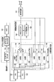
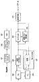
- FIG. 2 is a block diagram illustrating a reproduction signal processing unit in the information recording / reproducing apparatus according to the first embodiment.
- the figure which illustrates the offset suppression part of FIG. FIG. 3 is a trellis diagram for explaining the operation of the ARML filter of FIG. 1.
- the block diagram which illustrates the noise estimator of FIG. 2 is a diagram illustrating specifications of an optical recording medium that can be read by the information recording / reproducing apparatus according to the first embodiment.
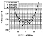
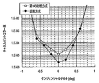
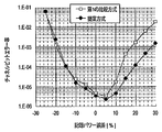
- the graph which shows the channel bit error rate characteristic with respect to a tangential tilt at the time of applying a 1st comparison system, a 2nd comparison system, and a 3rd comparison system The graph which shows the channel bit error rate characteristic with respect to tangential tilt at the time of applying a 1st comparison system and a proposal system.
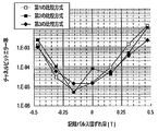
- FIG. 10 is a graph showing channel bit error rate characteristics with respect to recording power error when the first comparison method, the second comparison method, and the third comparison method are applied.
- the graph which shows the channel bit error rate characteristic with respect to recording power error at the time of applying a 1st comparison system and a proposal system.
- the table which shows the system margin regarding a tangential tilt at the time of applying a 1st comparison system, a 2nd comparison system, a 3rd comparison system, and a proposal system, a recording pulse width, and recording power.
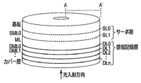
- FIG. 12A is a cross-sectional view taken along line A-A ′ of FIG.
- 9 is a flowchart illustrating a data recording process performed by the information recording / reproducing apparatus according to the second embodiment.
- 9 is a flowchart illustrating a data reproduction process performed by the information recording / reproducing apparatus according to the second embodiment.
- the information recording / reproducing apparatus can process a reproduced signal read from an optical recording medium.
- the information recording / reproducing apparatus according to the present embodiment can include a reproduction signal processing unit shown in FIG. 1 in order to process a reproduction signal.
- the reproduction signal processing unit in FIG. 1 effectively suppresses non-linear noise components remaining in the reproduction signal from the optical recording medium. Specifically, the reproduction signal processing unit sequentially performs offset component suppression processing, nonlinear distortion component suppression processing, and correlation noise component suppression processing.
- the reproduction signal processing unit includes a band pass filter 100, an offset canceller 110, an AGC (Auto Gain Controller) 120, an ITR (Interpolated Timing Recovery) 121, and a PLL (Phase Locked Loop) 122.
- the band pasta filter 100 and the offset canceller 110 function as an offset suppression unit.
- the Volterra filter 130 and the tap controller 140 function as a nonlinear distortion suppression unit.
- the ARML filter 150 and the noise estimator 160 function as a correlation noise suppression unit.
- the ITR 121 and the PLL 122 function as a synchronization processing unit.
- the offset suppression unit suppresses an offset component remaining in the input signal by performing signal processing that brings the center level of the input signal close to zero.
- the bandpass filter 100 inputs a reproduction signal read from an optical recording medium (not shown).
- the band pass filter 100 allows a signal component in a desired band of the input reproduction signal to pass and suppresses a signal component outside the band.
- the band pass filter 100 outputs the filtered signal to the offset canceller 110.
- the band pass filter 100 can be implemented using an IIR (Infinite Impulse Response) filter or an FIR filter.
- the band pass filter 100 may be replaced with a high pass filter.
- the offset canceller 110 inputs a signal from the band pass filter 100. Offset canceller 110 suppresses the offset component remaining in the input signal, and outputs the offset-suppressed signal to AGC 120. Specifically, the offset canceller 110 can suppress the offset component of the input signal by subtracting the DC component of the input signal from the input signal.
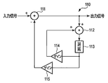
- the offset canceller 110 includes a subtractor 111, an adder 112, a delay device 113, and amplifiers 114 and 115, for example, as shown in FIG.
- the control band of the offset canceller 110 in FIG. 2 can be adjusted via the gains of the amplifiers 114 and 115.
- the subtractor 111 obtains an output signal by subtracting the signal fed back from the amplifier 115 from the input signal.
- the adder 112 adds the output signal from the subtractor 111 and the signal fed back from the amplifier 114 and outputs the result to the delay unit 113.
- the delay unit 113 inputs a signal from the adder 112 and gives a delay.
- the delay device 113 outputs the delayed signal to the amplifiers 114 and 115.
- the amplifier 114 receives the delayed signal from the delay unit 113, adjusts the amplitude according to the gain, and feeds it back to the adder 112.
- the amplifier 115 receives the delayed signal from the delay unit 113, adjusts the amplitude according to the gain, and feeds it back to the subtractor 111.
- the AGC 120 inputs the signal whose offset is suppressed from the offset suppression unit.
- the AGC 120 automatically adjusts the amplitude of the input signal so that the amplitude approaches the desired value.
- the AGC 120 outputs the amplitude-adjusted signal to the synchronization processing unit.
- the synchronization processing unit inputs a signal whose amplitude has been adjusted from the AGC 120.
- the synchronization processing unit adjusts the temporal variation of the frequency in the input signal.
- the synchronization processing unit outputs the signal subjected to the synchronization processing to the nonlinear distortion suppression unit.
- the Volterra filter 130 in the nonlinear distortion suppression unit suppresses nonlinear distortion components (for example, vertical asymmetry of the waveform) remaining in the input signal. Further, the tap controller 140 of the nonlinear distortion suppression unit dynamically updates the tap coefficient of the Volterra filter 130. Therefore, even if the non-linear distortion component remaining in the input signal fluctuates with time, the non-linear distortion suppression unit can stably suppress the non-linear distortion component. As described above, the nonlinear distortion suppression unit inputs the signal whose offset is suppressed. Therefore, it is possible to prevent a waveform shift due to an offset component from being erroneously suppressed as a vertically asymmetric component. In addition, the Volterra filter 130 can be stably adaptively controlled by setting the control band of the Volterra filter 130 of the nonlinear distortion suppression unit to a low control band of the offset suppression unit.
- the Volterra filter 130 receives the signal subjected to the synchronization processing from the synchronization processing unit.
- the Volterra filter 130 performs Volterra filter processing on the input signal, and outputs the filtered signal to the tap controller 140 and the correlation noise suppression unit.
- the Volterra filter 130 includes a filter arithmetic unit 131 for the first-order term, a filter arithmetic unit 132 for the second-order term, and a filter arithmetic unit 133 for the third-order term. it can. That is, the Volterra filter 130 in FIG. 1 can perform the third-order filter processing.
- the Volterra filter 130 can perform the filter processing represented by the following mathematical formula (1).
- Equation (1) the first term on the right side represents a primary filter operation (that is, a linear filter operation), the second term on the right side represents a secondary filter operation, and the third term on the right side represents a tertiary filter operation.
- the linear filter operation corresponds to normal FIR filter processing. According to the filter processing of Equation (1), higher-order distortion components can be suppressed in addition to the second-order distortion components (for example, waveform asymmetry).
- x (t) represents an input signal of the Volterra filter 130
- y (t) represents an output signal of the Volterra filter 130.
- h 1 represents a tap coefficient for linear filter operation
- h 2 represents a tap coefficient for secondary filter operation
- h 3 represents a tap coefficient for tertiary filter operation.
- t represents the sample timing.
- t ′ and t ′′ represent sample timings in which delays related to the second-order filter operation and the third-order filter operation are compensated.
- i is a variable for specifying a tap number in the linear filter calculation
- I represents a tap length in the linear filter calculation.
- j and k are variables for specifying the tap number in the secondary filter calculation
- J and K represent the tap length in the secondary filter calculation.
- J and K may be the same value or different values.
- f, g, and h are variables that specify the tap number in the third-order filter calculation, and F, G, and H represent the tap length in the third-order filter calculation. F, G, and H may be the same value or different values.
- the tap controller 140 updates the tap coefficient used by the Volterra filter 130.
- the tap controller 140 sequentially outputs the updated tap coefficient to the volterra filter 130.
- the tap controller 140 includes a tap coefficient calculator 141 for linear filter calculation, a tap coefficient calculator 142 for secondary filter calculation, and a tap coefficient for tertiary filter calculation. And a calculator 143.
- the tap controller 140 updates the tap coefficient according to the following mathematical formula (2).
- Equation (2) ⁇ 1 represents a step size parameter for linear filter operation, ⁇ 2 represents a step size parameter for secondary filter operation, and ⁇ 3 represents a step size parameter for tertiary filter operation. Represents. Note that the control band of the Volterra filter 130 can be adjusted via a step size parameter.
- Formula (2) is based on the LMS (Least Mean Square) method.
- the tap controller 140 may update the tap coefficient based on a technique other than the LMS.
- the noise estimator 160 in the correlation noise suppressing unit estimates a correlation noise component remaining in the input signal based on an AR (Auto-Regressive) model.
- the ARML filter 150 suppresses the correlation noise component remaining in the input signal.
- the noise estimator 160 is based on the assumption that white noise previously mixed in the input signal is converted into a correlation noise component and added to the input signal. Therefore, if the nonlinear distortion component as the colored noise is not sufficiently suppressed in the input signal, the estimation accuracy of the correlation noise component by the noise estimator 160 deteriorates, and as a result, the ARML filter 150 may not function effectively. .
- the correlation noise suppression unit inputs a signal in which nonlinear distortion is suppressed. Therefore, it is possible to prevent the nonlinear distortion component from adversely affecting the estimation of the correlation noise component.
- the ARML filter 150 can be adaptively controlled stably.
- the ARML filter 150 is an ML filter that can effectively suppress the correlation noise expressed by the AR model.
- noise autocorrelation is assumed.
- the ARML filter 150 performs equalization not on linear white noise but on colored noise having a different intensity for each input signal pattern and temporal correlation. Therefore, even if a noise component having a pattern dependency or a noise component having temporal correlation remains in the input signal, the ARML filter 150 can effectively suppress the noise component.
- the ML filter is realized based on Viterbi algorithm, BCJR (Bahl-Cocke-Jelinek-Raviv) algorithm, MLM (Max-Log-Map) algorithm, SOVA (Soft Output Viterbi Algorithm), or the like.
- an error correction process for example, a Reed-Solomon code decoding process
- the ML filter outputs the hard decision result Based on an algorithm (for example, a Viterbi equalization algorithm).
- the ML filter when an error correction process (for example, LDPC (Low Density Parity Check) code decoding process) is performed on the soft decision result after the ML filter, the ML filter outputs an algorithm (for example, BCJR). Algorithm, MLM algorithm or SOVA algorithm).
- an error correction process for example, LDPC (Low Density Parity Check) code decoding process
- the ML filter outputs an algorithm (for example, BCJR). Algorithm, MLM algorithm or SOVA algorithm).
- the ARML filter 150 calculates a likelihood index called a metric for each branch and determines the most probable path based on the metric, thereby obtaining a hard decision result or a soft decision result of the reproduction signal.
- the ARML filter 150 outputs the hard decision result or the soft decision result of the reproduction signal to the noise estimator 160 and the error correction unit 170.
- a branch refers to a transition from a state at a given time to a state at the next time, and an ideal signal can be derived for each branch.
- a path is a concatenation of one or more branches that have passed through to the state at a given time.
- the metrics of the branches constituting the path are integrated, and it is evaluated that the path with the smallest metric integrated value is most likely.
- the metric in the ML filter can be calculated, for example, according to the following formula (3).
- the ARML filter 150 can calculate the metric according to the following equation (4).
- L represents a noise correlation length
- the correlation coefficient set w omega noise.
- the offset error, the standard deviation of white noise, and the noise correlation coefficient set are estimated by the noise estimator 160.
- the binarizer 161 binarizes the output signal from the ARML filter 150 and outputs it to the PR channel filter 162.
- the binarizer 161 is not necessary.
- the PR channel filter 162 receives a binary signal from the binarizer 161 (or the ARML filter 150). The PR channel filter 162 performs a filtering process corresponding to the PR class on the binary signal to generate an ideal signal. For example, if the PR class employed in signal processing is 12221, the PR channel filter 162 can be implemented by an FIR filter using tap coefficients [1, 2, 2, 2, 1]. The PR channel filter 162 outputs the ideal signal to the subtracter 163.
- the subtractor 163 inputs the output signal of the nonlinear noise suppression unit as a reproduction signal, and inputs an ideal signal from the PR channel filter 162.
- the subtracter 163 subtracts the ideal signal from the reproduction signal and outputs a difference signal (that is, a noise component) to the selector 164.
- the calculated offset error m ⁇ , white noise standard deviation ⁇ ⁇ , and noise correlation coefficient set w ⁇ are output to a metric calculation unit (not shown) in the ARML filter 150 via a low-pass filter (LPF). Is done.
- LPF low-pass filter
- the noise estimator 160 is, for example, an input signal that is referred to in order to calculate noise parameters (that is, the calculated offset error m ⁇ , white noise standard deviation ⁇ ⁇ , and noise correlation coefficient set w ⁇ ).
- the control band of the ARML filter 150 can be adjusted through the number of samples and the LPF band.
- the noise estimator 160 may update the noise parameters sequentially as illustrated in FIG. 5 or may update the noise parameters in a different manner. Specifically, the noise estimator 160 may calculate an initial value of the noise parameter by using a part of the input signal as a training portion, and may continue to use the initial value until the next update timing. In this case, the noise estimator 160 can adjust the control band of the ARML filter 150 through the cycle of the update timing.
- the error correction unit 170 inputs the hard decision result or the soft decision result of the reproduction signal from the ARML filter 150.
- the error correction unit 170 performs deinterleaving processing corresponding to the interleaving processing performed at the time of data recording. Then, the error correction unit 170 obtains reproduced data by performing error correction decoding corresponding to error correction encoding (for example, Reed-Solomon encoding, LDPC encoding, etc.) performed at the time of data recording.
- error correction decoding for example, Reed-Solomon encoding, LDPC encoding, etc.
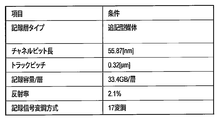
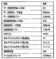
- the information recording / reproducing apparatus can reproduce data from an optical recording medium that satisfies the specification shown in FIG. 6A, for example.
- the information recording layer type is a write-once type
- the channel bit length is 55.87 [nm]
- the track pitch is 0.32 [ ⁇ m].
- the data recording capacity of each information recording layer is 33.4 GB
- the reflectance of each information recording layer is about 2%
- the data is recorded in a state modulated by 17 modulation methods.
- the information recording / reproducing apparatus satisfies the specifications shown in FIG. 6B, for example.
- the NA of the objective lens is 0.85
- the wavelength of the laser used for data recording / reproduction is 405 [nm]
- the reproduction power is 1.2 [mW].
- the PR class employed in signal processing is 12221
- the channel bit rate is 132 Mbps.
- the order of the Volterra filter 130 is 3, the number of taps of the linear filter operation is 13, the number of taps of the secondary filter operation is 13 ⁇ 13, and the number of taps of the tertiary filter operation is 7 ⁇ 7 ⁇ 7.
- the optical recording medium used in this experiment satisfies the specifications shown in FIG. 6A.
- a comparison method (referred to as a first comparison method for convenience) for this embodiment was prepared.
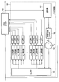
- the information recording / reproducing apparatus according to the first comparison method includes a reproduction signal processing unit shown in FIG. 7 includes a band pass filter 201, an offset canceller 202, an AGC 203, an ITR 204, a PLL 205, an FIR filter 206, a tap controller 207, an ML filter 208, a reference level detector 209, and the like. And an error correction unit 210.
- the reproduction signal processing unit in FIG. 7 is different from the reproduction signal processing unit in FIG. 1 in a function unit for suppressing nonlinear noise components.
- the nonlinear distortion suppression unit in FIG. 1 is replaced with the FIR filter 206 and the tap controller 207 in FIG.
- the correlation noise suppression unit in FIG. 1 is replaced with the ML filter 208 and the reference level calculator 209 in FIG.
- the band pass filter 201, the offset canceller 202, the AGC 203, the ITR 204, the PLL 205, and the error correction unit 210 of FIG. 7 correspond to the band pass filter 100, the offset canceller 110, the AGC 120, the ITR 121, the PLL 122, and the error correction unit 170 of FIG. To do.
- the FIR filter 206 performs FIR filter processing on the input signal using the tap coefficient given from the tap controller 207.
- the ML filter 208 differs from the ARML filter 150 in that no noise component based on the AR model is considered.
- the ML filter 208 and the reference level calculator 209 in the first comparison method are replaced with the correlation noise suppression unit in FIG. 1 (referred to as the second comparison method for convenience), and
- the FIR filter 206 and the tap controller 207 are replaced with the nonlinear distortion suppression component shown in FIG. 1 (referred to as a third comparison method).
- FIG. 8A and 8B show experimental results of channel bit error rate characteristics with respect to tangential tilt.
- FIG. 8A depicts experimental results of the first comparison method, the second comparison method, and the third comparison method.
- the tangential tilt means a tangential tilt [degree] of the optical recording medium during reproduction of the optical recording medium.
- the second comparison method and the third comparison method did not necessarily show better characteristics than the first comparison method.
- the nonlinear distortion suppression unit and the correlation noise suppression unit of FIG. 1 is introduced to the first comparison method, it is favorable for an optical recording medium that satisfies the specifications shown in FIG. 6A. It is difficult to achieve the characteristics stably.
- FIG. 8B shows experimental results of the proposed method (that is, the information recording / reproducing apparatus according to the present embodiment) in addition to the experimental results of the first comparison method.
- the proposed method achieved better characteristics than the first comparison method over a wide range. Therefore, at least with respect to tangential tilt, the proposed method can stably achieve good characteristics for an optical recording medium that satisfies the specification shown in FIG. 6A.
- FIG. 9A and 9B show experimental results of channel bit error rate characteristics with respect to recording pulse width deviation.
- FIG. 9A shows experimental results of the first comparison method, the second comparison method, and the third comparison method.
- the deviation of the recording pulse width means a deviation [T] from the optimum value of the recording pulse width at the time of recording on the optical recording medium.
- the mark size recorded on the optical recording medium changes. This change causes a nonlinear noise component in the reproduction signal.
- the second comparison method and the third comparison method did not necessarily show better characteristics than the first comparison method.
- the nonlinear distortion suppression unit and the correlation noise suppression unit of FIG. 1 is introduced to the first comparison method, it is favorable for an optical recording medium that satisfies the specifications shown in FIG. 6A. It is difficult to achieve the characteristics stably.
- FIG. 9B shows the experimental results of the proposed method in addition to the experimental results of the first comparative method.
- the proposed method achieved better characteristics than the first comparison method over a wide range. Therefore, at least with respect to the recording pulse width, the proposed method can stably achieve good characteristics for the optical recording medium that satisfies the specification shown in FIG. 6A.
- FIG. 10A and 10B show experimental results of channel bit error rate characteristics with respect to recording power error.
- FIG. 10A depicts experimental results of the first comparison method, the second comparison method, and the third comparison method.
- the recording power error means an error [%] with respect to the optimum value of the recording power at the time of recording on the optical recording medium.
- the mark size recorded on the optical recording medium changes. This change causes a nonlinear noise component in the reproduction signal.
- the second comparison method and the third comparison method did not necessarily show better characteristics than the first comparison method.
- the nonlinear distortion suppression unit and the correlation noise suppression unit of FIG. 1 is introduced to the first comparison method, it is favorable for an optical recording medium that satisfies the specifications shown in FIG. 6A. It is difficult to achieve the characteristics stably.
- FIG. 10B shows the experimental results of the proposed method in addition to the experimental results of the first comparative method.
- the proposed method achieved better characteristics than the first comparison method over a wide range. Therefore, at least regarding the recording power, the proposed method can stably achieve good characteristics for the optical recording medium that satisfies the specification shown in FIG. 6A.
- the system margin for each recording / reproducing condition of each method can be evaluated as shown in FIG.
- the system margin corresponds to an allowable error for various recording conditions. That is, although the reproduction characteristics are deteriorated according to the error regarding various recording conditions, if the error is within the system margin, it is possible to obtain correct reproduction data by error correction processing or the like.
- channel bit error rate 1.0E- 4 was used. This threshold value is an appropriate value in consideration of the correction capability of an error correction code scheme assumed to be applied to the error correction unit 170. According to FIG. 11, the proposed method can ensure a larger system margin than the first comparison method, the second comparison method, and the third comparison method for any recording / reproduction condition.
- the margins of the first comparison method, the second comparison method, and the third comparison method were all about 25 to 26%, whereas the margin of the proposed method was 8 points or more. It was a high 34%.
- the recording power margin in the optical recording medium is generally about 20 to 25%.
- various signal processing parameters can be set in the information recording / reproducing apparatus according to the present embodiment.
- the control band of the noise suppression unit, the number of taps used in the Volterra filter 130 and the control band of the Volterra filter 130, the noise correlation length used in the ARML filter 150, the control band of the ARML filter 150, etc. can be set Are prepared as various signal processing parameters.
- examples of setting these parameters will be referred to.
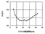
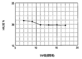
- FIG. 20A shows the measured value of i-MLSE when the control band of the offset suppression unit in the information recording / reproducing apparatus according to the present embodiment is changed.
- the horizontal axis represents the control band of the offset suppression unit
- the vertical axis represents i-MLSE.
- i-MLSE is a performance evaluation index disclosed in Non-Patent Document 1. It can be evaluated that the smaller the i-MLSE is, the smaller the noise component remaining in the equalized signal is, so that data can be stably reproduced.
- the control band of the offset suppression unit is set in a range between approximately 15 kHz and 25 kHz.
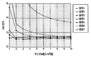
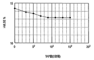
- FIG. 20B shows a change in i-MLSE with respect to an increase in the number of samples processed in the Volterra filter 130 in the information recording / reproducing apparatus according to the present embodiment.
- Condition 1-7 is prepared by setting the step size parameter smaller in steps. That is, the step size parameter of condition 1 is the largest, and the step size parameter of condition 7 is the smallest.
- the tap controller 140 adaptively controls the tap coefficient, the i-MLSE gradually converges to a good value as the number of processing samples increases. Then, the number of processing samples (in other words, time) required until convergence is smaller as the control band is higher (that is, the step size parameter is larger).
- i-MLSE gradually converges to a good value as the number of processed samples increases. Also, the smaller the step size parameter, the larger the number of processing samples required to converge. However, it is not always preferable to increase the step size parameter excessively. Regarding condition 1-2, i-MLSE does not improve even if the number of samples processed increases, but rather deteriorates slightly.
- the control band of the Volterra filter 130 is preferably set in a range of approximately 0.7 kHz or less.
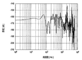
- FIG. 20C shows a frequency characteristic of a noise component of a certain pattern estimated by the noise estimator 160 in the information recording / reproducing apparatus according to the present embodiment.
- a large rise appears from 100 Hz to the low frequency side (approximately 60 Hz). Further, a plurality of large swells appear intermittently from 200 Hz to the high frequency side.
- the noise component on the low frequency side from 100 Hz should be suppressed by the adaptive control of the ARML filter 150.
- the noise component on the high frequency side from 200 Hz is a component resulting from variation in estimation by the noise estimator 160. Therefore, it is preferable that the control band of the ARML filter 150 is set lower than 300 Hz, for example.
- FIG. 21A shows i-MLSE measurement values when the number of taps used in the linear filter calculation of the Volterra filter 130 in the information recording / reproducing apparatus according to the present embodiment is changed.
- i-MLSE improves with an increase in the number of taps in a range of approximately 7 or more and 11 or less
- the improvement range of i-MLSE is small in a range of 11 or more. Therefore, the number of taps used in the linear filter calculation of the Volterra filter 130 is preferably 11 or more.
- FIG. 21B shows i-MLSE measurement values when the number of taps used in the secondary filter calculation of the Volterra filter 130 in the information recording / reproducing apparatus according to the present embodiment is changed.
- the range of 11 2 or less i-MLSE improves with increasing number of taps
- 11 improve the width of the i-MLSE is small in two or more ranges.
- the number of taps used in the secondary filter operation Volterra filter 130 is preferably 11 2 or more.
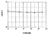
- FIG. 21C shows i-MLSE measurement values when the number of taps used in the third-order filter calculation of the Volterra filter 130 in the information recording / reproducing apparatus according to the present embodiment is changed.
- the number of taps used in the third-order filter operation Volterra filter is preferably 5 3 or more.
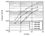
- FIG. 22 shows the change of the channel bit error rate in the output signal of the ARML filter 150 in the information recording / reproducing apparatus according to the present embodiment with respect to the change of the mark jitter of the optical recording medium.
- FIG. 22 shows the results when the noise correlation length used in the ARML filter 150 is set to 0 bit, 1 bit, 2 bits, and 3 bits.
- the noise correlation length used in the ARML filter 150 is set to 0 bit, 1 bit, 2 bits, and 3 bits.
- the noise correlation length is 1 bit
- the channel bit error rate is deteriorated as compared with the case where the noise correlation length is 0 bit (that is, when the ARML filter 150 corresponds to a normal ML filter). is doing.
- the noise correlation length is increased to 2 bits, the channel bit error rate is greatly improved.
- the noise correlation length used in the ARML filter 150 is preferably 2 bits or more.
- various signal processing parameters may be set to the values exemplified below.
- the control band of the offset suppression unit is set to 20 kHz
- the control band of the Volterra filter 130 is set to 0.7 kHz
- the control band of the ARML filter 150 is set to 200 kHz or less. According to this setting, since the control band of the offset suppression unit, the Volterra filter 130, and the ARML filter 150 is sequentially reduced, the Volterra filter 130 and the ARML filter 150 can be adaptively controlled stably.
- the number of taps used in the linear filter operation of the Volterra filter 130 is set to 13
- the number of taps used in the secondary filter operation is set to 13 ⁇
- the number of taps used in the tertiary filter operation is 7 ⁇ . 7 ⁇ 7 is set.
- the noise correlation length used in the ARML filter 150 is set to 2 bits.
- the information recording / reproducing apparatus sequentially applies offset suppression, nonlinear distortion suppression, and correlation noise suppression to a reproduction signal. Therefore, according to this information recording / reproducing apparatus, the non-linear noise component remaining in the reproduction signal read from the optical recording medium is effectively suppressed, and data can be stably reproduced from the optical recording medium. Further, according to the information recording / reproducing apparatus, a large system margin can be ensured for various recording / reproducing conditions.
- the information recording / reproducing apparatus includes a PUH (Pick Up Head) 300, a servo processing circuit 320, and a signal processing circuit 340.
- the information recording / reproducing apparatus of FIG. 17 can record / reproduce data on / from an optical recording medium that includes a servo layer and has multiple information recording layers.
- the solid line arrow represents the flow of the electric signal
- the alternate long and short dash line represents the flow of the blue laser (laser for the information recording layer)
- the broken line arrow represents the red laser (laser for the servo layer).
- the PUH 300 generates a servo layer laser and an information recording layer laser.
- the PUH 300 irradiates a part of the laser to the optical recording medium and outputs the remaining part to the servo processing circuit 320 in the form of an electric signal. Further, the PUH 300 outputs the return light from the optical recording medium to the servo processing circuit 320 in the form of an electric signal.
- the PUH 300 includes a red laser diode (LD) 301, a blue LD 302, an optical system 303, a red laser front monitor 304, a blue laser front monitor 305, a red laser aberration correction mechanism 306, and a blue laser aberration.
- a correction mechanism 307, an objective lens 308, an objective lens driving mechanism 309, a red laser light receiving element 310, a blue laser light receiving element 311, a red laser driving circuit 312, and a blue laser driving circuit 313 are provided. .
- the LD 301 is a light source of a red laser for the servo layer.
- the wavelength of the red laser is about 650 nm.
- the laser drive circuit 312 controls the intensity of the laser generated by the LD 301 in accordance with a control signal from a power control circuit 321 described later.
- the LD 302 is a blue laser light source for the information recording layer. The wavelength of the blue laser is about 405 nm.
- the laser driving circuit 313 controls the intensity of the laser generated by the LD 302 in accordance with control signals from a power control circuit 323 and a pulse modulation circuit 324 described later.
- the laser drive circuits 312 and 313 can turn on the LDs 301 and 302 at the same time.
- the optical system 303 divides the red laser into light for front monitoring and light for medium irradiation.
- the light for front monitor is condensed on the front monitor 304, and the light for medium irradiation is condensed on the servo layer of the optical recording medium via the aberration correction mechanism 306 and the objective lens 308.
- the return light from the servo layer is guided to the light receiving element 310 via the objective lens 308, the aberration correction mechanism 306, and the optical system 303.
- the light receiving element 310 converts the received light into an electrical signal and outputs it to a focus control circuit 325, a tracking control circuit 326, and a preamplifier 327, which will be described later.
- the front monitor 304 converts the front monitor light into an electrical signal and outputs it to the power control circuit 321.
- the aberration correction mechanism 306 Based on a control signal from an aberration control circuit 333, which will be described later, the aberration correction mechanism 306 generates various aberrations (for example, a spherical surface, a medium irradiation light, and a return light from the servo layer). Wavefront aberration is controlled by providing astigmatism and coma).
- the aberration correction mechanism 306 focuses the focused spot of the red laser on a desired servo layer based on the focus error signal from the focus control circuit 325.
- the optical system 303 divides the blue laser into light for front monitoring and light for medium irradiation.
- the light for front monitor is condensed on the front monitor 305, and the light for medium irradiation is condensed on the information recording layer of the optical recording medium via the aberration correction mechanism 307 and the objective lens 308.
- the return light from the information recording layer is guided to the light receiving element 311 via the objective lens 308, the aberration correction mechanism 307, and the optical system 303.
- the light receiving element 311 converts the received light into an electric signal and outputs it to a focus control circuit 329, a tracking control circuit 330, and a preamplifier 331, which will be described later.
- the front monitor 305 converts the light for front monitor into an electric signal and outputs it to the sample / hold circuit (S / H) 322. Based on a control signal from an aberration control circuit 334, which will be described later, the aberration correction mechanism 307 generates various aberrations (for example, a spherical surface, a medium irradiation light and a return light from the servo layer). Wavefront aberration is controlled by providing astigmatism and coma).
- the objective lens 308 is driven in the focus direction or the tracking direction by the objective lens driving mechanism 309, and the tilt state is controlled.
- the objective lens driving mechanism 309 inputs a tracking error signal from the tracking control circuit 326 when data is recorded on the optical recording medium.
- the objective lens driving mechanism 309 causes the focused spot of the red laser to follow the desired track based on the tracking error signal.
- the radial position of the focused spot of the blue laser is controlled together with the radial position of the focused spot of the red laser.
- the objective lens driving mechanism 309 inputs a focus error signal from the focus control circuit 329.
- the objective lens driving mechanism 309 focuses the focused spot of the blue laser on a desired information recording layer based on the focus error signal.
- the objective lens driving mechanism 309 inputs a tracking error signal from the tracking control circuit 330 when reproducing data from the optical recording medium.
- the objective lens driving mechanism 309 causes the focused spot of the blue laser to follow a desired track based on the tracking error signal.
- the objective lens driving mechanism 309 controls the tilt state of the objective lens 308 based on a control signal from a tilt control circuit 335 described later.
- the servo processing circuit 320 receives various electrical signals from the PUH 300 and the signal processing circuit 340, generates various control signals based on them, and outputs them to the PUH 300.
- the servo layer processing circuit 320 includes a red laser power control circuit 321, a sample / hold circuit 322, a blue laser power control circuit 323, a pulse modulation circuit 324, a red laser focus control circuit 325, and a red laser.
- the power control circuit 321 inputs an electric signal from the front monitor 304.
- the power control circuit 321 generates a control signal for bringing the input electric signal close to a desired value, and feeds it back to the laser drive circuit 312.
- the timing of the sample / hold circuit 322 is controlled by a control signal output from the pulse modulation circuit 324.
- the sample / hold circuit 322 samples / holds the electrical signal from the front monitor 305 and outputs it to the power control circuit 322.
- the power control circuit 323 inputs an electric signal from the sample / hold circuit 322.
- the power control circuit 323 generates a control signal for bringing the input electric signal close to a desired value and feeds it back to the laser driving circuit 313.
- the pulse modulation circuit 324 receives a reference clock signal from a clock generation unit 341, which will be described later, at the time of data recording, and a recording signal (for example, NRZI (Non Return to Zero Inversion), which will be described later). Signal).
- the pulse modulation circuit 324 generates a control signal based on the reference clock signal and the recording signal, and outputs the control signal to the laser driving circuit 313 and the sample / hold circuit 322.
- the laser intensity of the LD 302 is modulated in a pulse shape. For example, the laser intensity of the LD 302 is high when the recorded data is “1”, and the LD 302 is turned off when the recorded data is “0”.
- the focus control circuit 325 inputs an electric signal from the light receiving element 310.
- the focus control circuit 325 calculates an input electrical signal based on, for example, a knife edge method, an astigmatism method, and generates a focus error signal.
- the focus control circuit 325 outputs a focus error signal to the aberration correction mechanism 306.
- the tracking control circuit 326 inputs an electric signal from the light receiving element 310 when data is recorded on the optical recording medium.
- the tracking control circuit 325 calculates an input electrical signal based on, for example, a push-pull method, a DPP (Differential Push-Pull) method, and generates a tracking error signal.
- the tracking control circuit 326 outputs a tracking error signal to the objective lens driving mechanism 309 and a PUH driving mechanism (not shown).
- the preamplifier 327 inputs an electric signal from the light receiving element 310.
- the preamplifier 327 adjusts the amplitude of the input electric signal according to the gain, and outputs it to the A / D 328.
- the A / D 328 receives a signal from the preamplifier 327, performs analog-digital conversion, and outputs the signal to the signal processing circuit 340.
- the focus control circuit 329 inputs an electric signal from the light receiving element 311.
- the focus control circuit 329 calculates an input electrical signal based on, for example, a knife edge method, an astigmatism method, and generates a focus error signal.
- the focus control circuit 329 outputs a focus error signal to the objective lens driving mechanism 309.
- the tracking control circuit 330 inputs an electrical signal from the light receiving element 311 when reproducing data from the optical recording medium.
- the tracking control circuit 330 calculates an input electric signal based on, for example, a DPD (Differential Phase Detection) method, and generates a tracking error signal.
- the tracking control circuit 330 outputs a tracking error signal to the objective lens driving mechanism 309 and a PUH driving mechanism (not shown).
- the preamplifier 331 inputs an electric signal from the light receiving element 311.
- the preamplifier 331 adjusts the amplitude of the input electric signal according to the gain, and outputs the adjusted signal to the A / D 332.
- the A / D 332 receives a signal from the preamplifier 331, performs analog-digital conversion, and outputs the signal to the signal processing circuit 340.
- the aberration control circuit 333 receives aberration error data from an aberration error calculation unit 344 described later, and generates a control signal based on the aberration error data.
- the aberration control circuit 333 outputs a control signal to the aberration correction mechanism 306.
- the aberration control circuit 334 receives aberration error data from an aberration error calculator 345 described later, and generates a control signal based on the aberration error data.
- the aberration control circuit 334 outputs a control signal to the aberration correction mechanism 307.
- the tilt control circuit 335 inputs tilt error data from a tilt error calculation unit 346 or 347 described later, and generates a control signal based on the tilt error data.
- the tilt control circuit 335 outputs a control signal to the objective lens driving mechanism 309.
- the signal processing circuit 340 processes a reproduction signal from the optical recording medium and generates a recording signal to the optical recording medium.
- the signal processing circuit 340 includes a clock generation unit 341, an address processing unit 342, a signal processing unit 343, a red laser aberration error calculation unit 344, a blue laser aberration error calculation unit 345, and a red laser tilt error calculation.
- the clock generator 341 generates a reference clock signal and supplies it to the pulse modulation circuit 324.
- the address processing unit 342 performs processing related to address information such as reading of address information. The read address information is transmitted to the controller.
- the signal processing unit 343 includes a reproduction signal processing unit illustrated in FIG. 1 and a recording signal processing unit (not shown).
- the recording signal processing unit inputs user data from a controller (not shown), and converts the user data into a data string that can be recorded on an optical recording medium. Specifically, the recording signal processing unit performs scramble processing on the user data to randomize the data pattern, or error correction coding (for example, Reed-Solomon coding, LDPC code) for error correction. Etc.) and an interleaving process for avoiding continuous errors. Further, the recording signal processing unit adds a sector-address number corresponding to the address information of the data to the user data, and adds a burst detection subcode for detecting a burst error.
- error correction coding for example, Reed-Solomon coding, LDPC code
- the recording signal processing unit performs 17PP (Parity Preserved) modulation or ETM (Eight to Twelve Modulation) in order to control the minimum inversion length of the user data by restricting the run length, and performing NRZI conversion to perform optical A data string that can be recorded on a recording medium is obtained.
- the reproduction signal processing unit inputs reproduction signals from A / D 328 and A / D 332, and performs adaptive filter processing for suppressing the nonlinear noise component described with reference to FIG. Further, the reproduction signal processing unit performs a demodulation process corresponding to the modulation scheme that restricts the run length described above on the reproduction signal, or performs error correction decoding corresponding to the error correction coding scheme, Restore user data. The restored user data is transmitted to the controller.
- the aberration error calculation unit 344 receives a digital signal from the A / D 328 and calculates an aberration error amount based on the digital signal.
- the aberration error calculation unit 344 outputs the aberration error data to the aberration control circuit 333.
- the aberration error calculation unit 345 receives a digital signal from the A / D 332 and calculates an aberration error amount based on the digital signal.
- the aberration error calculation unit 345 outputs the aberration error data to the aberration control circuit 334.
- the tilt error calculation unit 346 receives a digital signal from the A / D 328 and calculates a tilt error amount based on the digital signal.
- the tilt error calculation unit 346 outputs tilt error data to the tilt control circuit 335.
- the tilt error calculation unit 347 receives a digital signal from the A / D 332 and calculates a tilt error amount based on the digital signal.
- the tilt error calculation unit 347 outputs tilt error data to the tilt control circuit 335.
- FIG. 12A illustrates an optical recording medium having a servo layer that can be read by the information recording / reproducing apparatus according to the present embodiment.
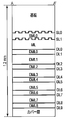
- 12B is a cross-sectional view taken along the line A-A ′ of FIG. 12A.
- the outer shape of the optical recording medium is disk-shaped, and a clamp hole is formed at the center thereof.
- the optical recording medium has a layer structure in which two servo layers and a plurality of information recording layers are formed.
- a servo layer is provided on the back side when viewed from the light incident direction, and an information recording layer is provided on the front side.
- the disk substrate the servo layer 0 (SL0), the servo interlayer intermediate layer 0 (SML0), the servo layer 1 (SL1), and the intermediate layer (ML) in order from the back as viewed from the light incident direction.
- a cover layer is provided on the most front side when viewed from the light incident direction.
- the thickness of the optical recording medium is 1.2 mm, and the thickness of the disk substrate is about 0.8 mm.
- the thickness of the servo interlayer intermediate layer No. 0 (SML0) is determined in consideration of the wavelength of the laser for the servo layer (for example, 605 nm), and can be designed to be, for example, 55 ⁇ m.
- the intermediate layer (ML) has a thickness of 126 ⁇ m.
- the cover layer has a thickness of 50 ⁇ m.
- a plurality of types of thicknesses may be designed for the information recording interlayer. If the adjacent information recording interlayers are appropriately designed to have different thicknesses, the reflected light from the non-reproducing layer is not condensed on the reproducing layer.
- the thickness of the first type layer is designed to be relatively thin (for example, 12 ⁇ m)
- the thickness of the second type layer is designed to be relatively thick (for example, 16 ⁇ m).
- the thickness of the optical recording medium can be reduced by designing the total number of the first type layers to be equal to or greater than the total number of the second type layers. In the optical recording medium shown in FIGS.
- the even-numbered information recording interlayers (DML0, DML2,7) are treated as the first type layers, and the odd-numbered information recording interlayers ( It is preferable to design DML1, DML3, etc To be handled as the second type of layer. Note that if the thickness of the optical recording medium is reduced, aberrations that occur when reproducing the inner layer can be reduced.
- the thickness of each layer can be designed based on the wavelength of the laser for the information recording layer and the wavelength of the laser for the servo layer. For example, since the wavelength of the servo layer laser is longer than the wavelength of the information recording layer laser, the thickness of the servo interlayer interlayer is smaller than that of the information recording interlayer interlayer in order to reduce the influence of interlayer crosstalk. Designed thick. Further, no interlayer jump operation of the focused spot occurs between the servo layer and the information recording layer. Therefore, the thickness of the intermediate layer (ML) is designed to be thicker than that of the servo interlayer, thereby reducing the influence of crosstalk.
- the servo interlayer intermediate layer, the intermediate layer (ML), and the information recording interlayer interlayer are all designed to exhibit a transmittance close to 100% with respect to the servo layer laser and the information recording layer laser.
- the servo layer is formed of a film made of a metal having a thickness of submicron order.
- the servo layer No. 0 (SL0) is formed of a film that exhibits a semi-transmission characteristic that reflects part of the servo layer laser and transmits part of the laser.
- tracks serving as servo guides are formed in the servo layer.
- the information recording layer is composed of a multilayer film including a storage material capable of recording / reproducing and erasing information with a laser for the information recording layer. This multilayer film exhibits the characteristic of transmitting the servo layer laser. Further, this multilayer film exhibits the characteristics of transmitting a part of the laser for the information recording layer, reflecting a part thereof, and absorbing a part thereof.
- FIG. 13 shows an example of the servo layer and the information recording layer.
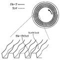
- a spiral track is formed on the servo layer.
- tracks are formed in spiral shapes in opposite directions on both servo layers. That is, if a track is formed in a clockwise spiral on the servo layer 0 (SL0), a track is formed in a counterclockwise spiral on the servo layer 1 (SL1). Conversely, tracks may be formed in a counterclockwise spiral shape on the servo layer 0 (SL0), and tracks may be formed in a clockwise spiral shape on the servo layer 1 (SL1).
- the track is provided with continuously formed grooves.
- the groove is given a minute vibration (wobble) in the radial direction of the optical recording medium.
- By modulating the frequency or phase of this wobble, or by placing recording marks such as prepits on part of the track, address information indicating the track number and circumferential position, and disc information indicating the characteristics of the optical recording medium Etc. are recorded in the servo layer.
- a preformat area is formed on the inner periphery and outer periphery of the information recording layer. In the inner circumference preformat area and the outer circumference preformat area, a learning pattern for optimizing the recording waveform, management information for managing the disk, and the like are recorded.
- the disc information shown in FIG. 16 is recorded on the servo layer using wobble modulation or recording marks.
- the disc information can include information indicating the type of the disc format, information indicating the disc size (for example, a physical size such as the diameter of the optical recording medium), and information indicating the maximum transfer rate.
- the disc information includes information indicating the number of servo layers, information indicating the number of information recording layers, and information indicating the type of format applicable to the information recording layer (for example, once recording, packet recording, etc.). Can do.
- the disc information can include information indicating the recording density (for example, the track pitch of the recording mark row, the mark pitch in the linear direction, etc.).
- the disc information an arrangement of areas in which user data is recorded among areas assigned addresses in the optical recording medium and information other than the user data (for example, a learning pattern for optimizing the recording waveform) are recorded.
- Information area arrangement information indicating the arrangement of the management information recording area can be included.
- the disc information includes information indicating the order of the Volterra filter 130 suitable for reproduction of the optical recording medium (for example, the optimum) and the number of taps required for the filter operation of each order, and the noise correlation length required in the ARML filter 150. Indicating information.
- the disc information includes information indicating the control band of the adaptive control filter (for example, the step size parameter of the Volterra filter 130, the band for calculating the noise parameter given to the ARML filter 150 (or the period of the update timing of the noise parameter), etc.). Can be included.
- the disc information indicates information indicating the reproduction power allowed by the optical recording medium, information indicating the recording power suitable for the optical recording medium (for example, optimum), and the shape of the recording pulse (for example, width, interval, etc.). Recording pulse information. Further, a spare area may be provided in the optical recording medium for disc information.
- spiral tracks are formed on the servo layer. As shown in FIG. 14, this track is formed by carving a groove on a surface called a land. The groove is formed so as to be displaced in the inner circumferential direction or the outer circumferential direction by half of the groove pitch for each round of the optical recording medium. Accordingly, the track has a single spiral structure in which the groove and the land are alternately switched every round of the optical recording medium.
- FIG. 15 illustrates wobble phase modulation.
- 1-bit information is expressed by the phase of four sine wave wobbles.
- the phase in which the meandering first advances toward the inner circumference side in the scanning direction is assigned to “0”, and the phase in which the first meandering advances outward in the scanning direction is assigned to “1”.
- the recording waveform is a type of waveform called a multi-pulse in which a plurality of pulses are used to record one mark. Of these multiple pulses, the first one is called the first pulse and the last one is called the last pulse. Of these multiple pulses, pulses other than the first pulse and the last pulse are referred to as multi-pulses. After the last pulse, a period (cooling pulse) for outputting bias power 1 is prepared.
- the shape of the recording waveform is defined by using four levels of recording power, erasing power, bias power 1 and bypass power 2 with respect to the level.
- the shape of the recording waveform is defined with respect to time using various time parameters based on the rising edge of the NRZI signal and the clock signal.
- the time information includes, for example, a first pulse start time F1, a first pulse end time F3, a first pulse interval F2, and the like.
- time parameters that easily affect the formation of recording marks such as the first pulse start time F1 and the last pulse end time L3 may be dynamically changed during data recording in accordance with the NRZI signal.
- Various parameters that determine the shape of the recording waveform are managed in the memory of the information recording / reproducing apparatus as shape information of the recording waveform, and are recorded on the optical recording medium as physical format information and management information.
- the reference clock is used for timing control in the information recording / reproducing apparatus.
- T represents the period of the reference clock.
- the reference clock is generated by the clock generation unit 341 described above.
- the NRZI signal is obtained by converting recording data into the NRZI format.
- the above-described pulse modulation circuit 324 When recording data on the optical recording medium, the above-described pulse modulation circuit 324 generates a recording pulse based on the shape information of the recording waveform and the NRZI signal output from the signal processing unit 343.
- the laser drive circuit 313 drives the LD 302 according to the recording pulse.
- the power of the laser applied to the optical recording medium is modulated as shown in the recording waveform shown in FIG.
- the information recording / reproducing apparatus controls the shape of the recording mark through the recording power level, the width of each pulse, and the like. For example, as the recording power level increases, the width of the recording mark increases. Further, if the start time of the first pulse is advanced, the start position of the recording mark is advanced, and as a result, the recording mark length becomes longer. In other words, if the recording power level, the width of each pulse, etc. deviate from the optimum values, the shape of the recording mark also changes from the optimum shape, so that a nonlinear noise component is generated in the reproduction
- system margin was evaluated based on the experimental results.
- system margins are subdivided and assigned as allowable values for various error factors. For example, if the recording power margin is 25%, about 12% is assigned as the tolerance for the recording power error of the information recording / reproducing apparatus, and the remaining 13% is assigned as the tolerance for the manufacturing error of the optical recording medium.
- An error in recording power in an information recording / reproducing apparatus mainly includes two types of elements.
- One element is an error generated in the automatic power adjustment process for maintaining the recording power constant, and the other element is an error generated in the recording power optimization process for determining the optimum recording power for the optical recording medium. . Therefore, 6% is assigned as an allowable value for these two error elements.
- the manufacturing error of the optical recording medium also mainly includes two types of elements. One element is a characteristic variation between optical recording media, and the other element is a characteristic variation between information recording layers in the same optical recording medium. 8% is assigned as a tolerance for variation in characteristics between optical recording media, and 5% is assigned as a tolerance for variations in characteristics of each information recording layer in the optical recording medium. If the information recording / reproducing apparatus and the optical recording medium are designed based on the assigned tolerance, the information recording / reproducing apparatus can stably reproduce data from the optical recording medium.
- the characteristics of the information recording layer include not only variations in sensitivity with respect to the recording power of the information recording layer but also variations in transmittance that determine the amount of light passing through the information recording layer. That is, when the information recording layer is multilayered, in addition to variations in sensitivity of a given information recording layer, one or more formed on the front side (laser incident surface side) of the information recording layer It is necessary to consider variations in the transmittance of the information recording layer.
- the sensitivity variation of each information recording layer is about 3% and the transmittance variation of each information recording layer is about 1%.
- the variation in characteristics of the information recording layer formed on the most front side is estimated to be 3%.
- the variation in characteristics of the information recording layers formed in the second and subsequent layers is evaluated by adding the variation in transmittance of the information recording layer formed in front of the information recording layer. That is, the variation in characteristics of the second information recording layer was estimated to be 4%, and the variation in characteristics of the information recording layer formed in the third layer was estimated to be 5%.
- the recording power margin is increased to 34%. Therefore, by assigning a part of the enlarged margin as an allowable value for the characteristic variation of each information recording layer in the optical recording medium, the allowable value can be increased to, for example, 10%. Therefore, according to the information recording / reproducing apparatus according to the present embodiment, the data can be stably recorded on the optical recording medium in which the information recording layer is composed of four or more layers without improving the film characteristics of the information recording layer. Can be recorded and reproduced. That is, by multilayering the conventional information recording layer, an optical recording medium capable of stably recording and reproducing data can be manufactured at low cost.
- the information recording layer does not have a guide groove structure. Therefore, the manufacturing cost of the optical recording medium can be reduced. In addition, since light is not diffracted by the groove structure, the transmittance of the information recording layer can be improved. That is, it is possible to suppress a decrease in the reflectance of the optical recording medium due to the multilayered information recording layer.
- the servo layer laser and the information recording layer laser are different as described above.
- the focused spot of the laser for the information recording layer is positioned according to the guide of the servo layer.
- the radial positions of the condensing spots of the laser for the information recording layer and the laser for the servo layer do not completely coincide with each other, and both of them are caused by the tilt of the optical recording medium or the objective lens. There is a misalignment between the two.
- the optical recording medium provided with the servo layer is positioned in the radial direction of the focused spot of the laser for the information recording layer as compared with a normal optical recording medium (that is, the information recording layer has a guide groove structure). It is inferior in accuracy. Therefore, according to the optical recording medium including the servo layer, for example, the positioning procedure in the additional recording process that is resumed after the data recording is interrupted becomes more complicated than that of a normal optical recording medium.
- an information recording / reproducing apparatus performs the above-described recording power optimization process in, for example, a preformat area in an information recording layer when recording data on an optical recording medium. Specifically, the information recording / reproducing apparatus records a learning test pattern while changing the recording power in a specific area in the information recording layer, and reproduces the recorded test pattern to thereby record the information recording layer. Determine the optimal power. According to a normal optical recording medium, the error in the recording power optimization process can be suppressed to about 6%. On the other hand, according to the optical recording medium provided with the servo layer, the above-described deterioration in positioning accuracy, complication of the positioning procedure, and the like are affected. .
- the information recording / reproducing apparatus distributes a part of the above-described margin increase as an allowable value for an error caused by the recording power optimization process, thereby expanding the allowable value to 9%, for example.
- Data can be stably recorded and reproduced with respect to an optical recording medium having a layer.
- the information recording / reproducing apparatus can read, for example, an optical recording medium that satisfies the specifications shown in FIG. 19A.
- the information recording layer type is a write-once type
- the number of servo layers is 2
- the guide structure formed in each servo layer is a land groove
- the number of information recording layers is The channel bit length is 56.28 [nm].
- the track pitch is 0.32 [ ⁇ m]
- the recording capacity of data in each information recording layer is 32.0 GB
- the reflectance of each information recording layer is about 1%
- the data is converted by 17 modulation methods. Recorded in a modulated state.
- the information recording / reproducing apparatus satisfies the specification shown in FIG. 19B, for example. 19B, the NA of the objective lens for the servo layer is 0.6, the wavelength of the laser for the servo layer is 660 [nm], and the reproduction power for the servo layer is 2.0 [mW ].
- the NA of the objective lens for the information recording layer is 0.85, the wavelength of the laser for the information recording layer is 405 [nm], and the reproduction power for the information recording layer is 1.2 [mW].
- the PR class employed in signal processing is 12221, and the channel bit rate is 132 Mbps.
- the order of the Volterra filter 130 is 3, the number of taps of the linear filter operation is 13, the number of taps of the secondary filter operation is 13 ⁇ 13, and the number of taps of the tertiary filter operation is 7 ⁇ 7 ⁇ 7. .
- the information recording / reproducing apparatus performs, for example, the data recording process shown in FIG. 23A on an optical recording medium having a servo layer.
- the data recording process in FIG. 23A starts from step ST1-1.
- the information recording / reproducing apparatus turns on a servo layer laser (for example, a red laser having a wavelength of 660 [nm]), and focuses the focused spot of the laser on a desired servo layer in the optical recording medium. Focus on.
- the information recording / reproducing apparatus reads the disk information from the guide track formed in the desired servo layer using the servo layer laser (step ST1-2).
- the disc information read in step ST1-2 is, for example, as shown in FIG.
- the information recording / reproducing apparatus can confirm the number of information recording layers in the optical recording medium, the type of format applicable to the information recording layer, and the like by referring to the disc information.
- the information recording / reproducing apparatus starts processing for the information recording layer based on the disc information read in step ST1-2. Specifically, the information recording / reproducing apparatus turns on a laser for an information recording layer (for example, a blue laser having a wavelength of 405 [nm]), and uses the focused spot of the laser to record desired information on an optical recording medium. Focus on the layer (step ST1-3). Subsequently, the information recording / reproducing apparatus records the condensing spot of the laser for the servo layer and the information recording layer for optimizing the recording condition on the information recording layer based on the guide track formed on the servo layer. Move to the radial position set as the learning area (step ST1-4). The information recording / reproducing apparatus performs recording learning in the recording learning area and optimizes recording power, pulse width, and the like (step ST1-5). When step ST1-5 is completed, the process proceeds to step ST1-6.
- a laser for an information recording layer for example, a blue laser having a wavelength of 405 [nm]
- step ST1-6 the information recording / reproducing apparatus moves the converging spot of the laser for the servo layer and the information recording layer to a desired radial position in the information recording layer based on the guide track formed in the servo layer.
- the information recording / reproducing apparatus records user data based on the recording power, pulse width, etc. optimized in step ST1-5 (step ST1-7). Step ST1-7 is repeated until all target user data is recorded (step ST1-8), and the data recording process is completed.
- the information recording / reproducing apparatus performs, for example, the data reproducing process shown in FIG. 23B on the optical recording medium having the servo layer.
- the data reproduction process in FIG. 23B starts from step ST2-1.
- the information recording / reproducing apparatus turns on a servo layer laser (for example, a red laser having a wavelength of 660 [nm]), and the focused spot of the laser is changed to a desired servo layer in the optical recording medium. Focus on.
- the information recording / reproducing apparatus reads the disk information from the guide track formed in the desired servo layer using the servo layer laser (step ST2-2).
- the disc information read in step ST2-2 is, for example, as shown in FIG.
- the information recording / reproducing apparatus can confirm the number of information recording layers in the optical recording medium, the type of format applicable to the information recording layer, and the like by referring to the disc information. Further, the information recording / reproducing apparatus can confirm the number of equalizer taps (for example, the number of taps of the Volterra filter 130) suitable for reproducing data from the information recording layer of the optical recording medium and the noise correlation length of the ARML filter 150. . Further, the information recording / reproducing apparatus can control band information of an adaptive control filter suitable for reproducing data from the information recording layer of the optical recording medium (for example, a step size parameter of the Volterra filter 130, a noise parameter given to the ARML filter 150). Can be confirmed (or the noise parameter update timing period).
- the information recording / reproducing apparatus sets various signal processing parameters based on the disc information read in step ST2-2 (step ST2-3). Specifically, the information recording / reproducing apparatus sets the number of taps of the Volterra filter 130 or sets the noise correlation length of the ARML filter 150. Further, the information recording / reproducing apparatus sets control bands for the offset suppression unit, the Volterra filter 130, and the ARML filter 150. When step ST2-3 is completed, the process proceeds to step ST2-4.
- step ST2-4 the information recording / reproducing apparatus turns on the laser for the information recording layer (for example, a blue laser having a wavelength of 405 [nm]), and sets the focused spot of the laser to desired information on the optical recording medium. Focus on the recording layer. Subsequently, the information recording / reproducing apparatus moves the condensing spot of the laser for the servo layer and the information recording layer to a desired radial position in the information recording layer based on the guide track formed in the servo layer (step ST2-5). The information recording / reproducing apparatus reads user data (step ST2-6). When all target user data is read, the data reproduction process is completed. Incidentally, according to the data reproduction process of FIG. 23B, various signal processing parameters are set to appropriate values in step ST2-3. Therefore, data can be stably reproduced from an optical recording medium having a servo layer and having multiple information recording layers.
- the laser for the information recording layer for example, a blue laser having a wavelength of 405 [nm]
- the information recording / reproducing apparatus records / reproduces data on / from an optical recording medium including a servo layer and having a multilayered information recording layer. Specifically, since this information recording / reproducing apparatus performs the same or similar reproduction signal processing as in the first embodiment, nonlinear noise components in the reproduction signal can be effectively suppressed. Therefore, according to the information recording / reproducing apparatus, a large system margin is ensured, so that data can be stably recorded / reproduced on the optical recording medium.
- the processing of each of the above embodiments can be realized by using a general-purpose computer as basic hardware.
- the program for realizing the processing of each of the above embodiments may be provided by being stored in a computer-readable storage medium.
- the program is stored in the storage medium as an installable file or an executable file. Examples of the storage medium include a magnetic disk, an optical disk (CD-ROM, CD-R, DVD, etc.), a magneto-optical disk (MO, etc.), and a semiconductor memory.
- the storage medium may be any as long as it can store the program and can be read by the computer.
- the program for realizing the processing of each of the above embodiments may be stored on a computer (server) connected to a network such as the Internet and downloaded to the computer (client) via the network.
Landscapes
- Engineering & Computer Science (AREA)
- Signal Processing (AREA)
- Signal Processing For Digital Recording And Reproducing (AREA)
- Optical Recording Or Reproduction (AREA)
Abstract
Selon le mode de réalisation de la présente invention, un appareil de traitement de signal est fourni avec une première unité de traitement de signal, une deuxième unité de traitement de signal, et une troisième unité de traitement de signal. La première unité de traitement de signal supprime des composantes de décalage laissées dans des signaux de reproduction lus sur un support d'enregistrement optique, et obtient des premiers signaux. La deuxième unité de traitement de signal supprime les composantes de contrainte non linéaires laissées dans les premiers signaux, et obtient des deuxièmes signaux. La troisième unité de traitement de signal supprime des composantes de bruit de corrélation laissées dans les deuxièmes signaux, et obtient des troisièmes signaux.
Priority Applications (3)
| Application Number | Priority Date | Filing Date | Title |
|---|---|---|---|
| PCT/JP2012/056918 WO2013136519A1 (fr) | 2012-03-16 | 2012-03-16 | Appareil de traitement de signal et appareil de reproduction d'informations |
| JP2014504598A JP5714177B2 (ja) | 2012-03-16 | 2012-03-16 | 信号処理装置及び情報再生装置 |
| US14/487,689 US9117485B2 (en) | 2012-03-16 | 2014-09-16 | Signal processing apparatus capable of suppressing non-linear noise component during reading optical recording medium |
Applications Claiming Priority (1)
| Application Number | Priority Date | Filing Date | Title |
|---|---|---|---|
| PCT/JP2012/056918 WO2013136519A1 (fr) | 2012-03-16 | 2012-03-16 | Appareil de traitement de signal et appareil de reproduction d'informations |
Related Child Applications (1)
| Application Number | Title | Priority Date | Filing Date |
|---|---|---|---|
| US14/487,689 Continuation US9117485B2 (en) | 2012-03-16 | 2014-09-16 | Signal processing apparatus capable of suppressing non-linear noise component during reading optical recording medium |
Publications (1)
| Publication Number | Publication Date |
|---|---|
| WO2013136519A1 true WO2013136519A1 (fr) | 2013-09-19 |
Family
ID=49160484
Family Applications (1)
| Application Number | Title | Priority Date | Filing Date |
|---|---|---|---|
| PCT/JP2012/056918 Ceased WO2013136519A1 (fr) | 2012-03-16 | 2012-03-16 | Appareil de traitement de signal et appareil de reproduction d'informations |
Country Status (3)
| Country | Link |
|---|---|
| US (1) | US9117485B2 (fr) |
| JP (1) | JP5714177B2 (fr) |
| WO (1) | WO2013136519A1 (fr) |
Families Citing this family (4)
| Publication number | Priority date | Publication date | Assignee | Title |
|---|---|---|---|---|
| KR102029154B1 (ko) * | 2014-12-26 | 2019-10-07 | 카와사키 주코교 카부시키 카이샤 | 자주식 관절 로봇 |
| US10887022B2 (en) | 2017-06-15 | 2021-01-05 | Nokia Of America Corporation | Backward propagation with compensation of some nonlinear effects of polarization mode dispersion |
| CN113067786B (zh) * | 2020-01-02 | 2023-08-29 | 上海诺基亚贝尔股份有限公司 | 用于均衡信号的设备、方法、装置及计算机可读介质 |
| JP2022045663A (ja) * | 2020-09-09 | 2022-03-22 | 株式会社東芝 | 磁気ディスク装置及びリード処理方法 |
Citations (3)
| Publication number | Priority date | Publication date | Assignee | Title |
|---|---|---|---|---|
| JP2002367291A (ja) * | 2001-06-11 | 2002-12-20 | Fujitsu Ltd | 情報記録再生装置及び方法並びに信号復号回路 |
| JP2006313592A (ja) * | 2005-05-09 | 2006-11-16 | Sony Corp | 信号処理装置および方法、プログラム記録媒体、並びにプログラム |
| JP2011192377A (ja) * | 2010-02-22 | 2011-09-29 | Tdk Corp | 光記録媒体、光記録再生方法 |
Family Cites Families (11)
| Publication number | Priority date | Publication date | Assignee | Title |
|---|---|---|---|---|
| JP4027444B2 (ja) * | 1996-03-11 | 2007-12-26 | 富士通株式会社 | 信号再生方法及び信号再生装置 |
| US6185175B1 (en) * | 1998-12-02 | 2001-02-06 | Cirrus Logic, Inc. | Sampled amplitude read channel employing noise whitening in a remod/demod sequence detector |
| JP2002117585A (ja) | 2000-06-09 | 2002-04-19 | Tdk Corp | 光情報媒体 |
| SE521130C2 (sv) * | 2002-04-17 | 2003-10-07 | Dirac Res Ab | Digital audiokompensering |
| JP4142537B2 (ja) * | 2003-09-19 | 2008-09-03 | 松下電器産業株式会社 | 光ディスク装置 |
| JP4276516B2 (ja) | 2003-10-20 | 2009-06-10 | パイオニア株式会社 | 多層光記録媒体および光ピックアップ装置 |
| WO2007010994A1 (fr) * | 2005-07-20 | 2007-01-25 | Matsushita Electric Industrial Co., Ltd. | Dispositif de reproduction de signal numérique |
| TWI346329B (en) * | 2006-03-14 | 2011-08-01 | Ricoh Co Ltd | Data reproduction method, data reproduction apparatus, optical disk, and data recording/reproduction apparatus |
| JP4720768B2 (ja) | 2007-03-28 | 2011-07-13 | 株式会社日立製作所 | ディスク状媒体及びディスク装置 |
| JPWO2012063326A1 (ja) | 2010-11-09 | 2014-05-12 | 株式会社東芝 | 情報記録媒体、情報再生装置及び情報記録装置 |
| US8767869B2 (en) * | 2011-08-18 | 2014-07-01 | Qualcomm Incorporated | Joint linear and non-linear cancellation of transmit self-jamming interference |
-
2012
- 2012-03-16 WO PCT/JP2012/056918 patent/WO2013136519A1/fr not_active Ceased
- 2012-03-16 JP JP2014504598A patent/JP5714177B2/ja active Active
-
2014
- 2014-09-16 US US14/487,689 patent/US9117485B2/en active Active
Patent Citations (3)
| Publication number | Priority date | Publication date | Assignee | Title |
|---|---|---|---|---|
| JP2002367291A (ja) * | 2001-06-11 | 2002-12-20 | Fujitsu Ltd | 情報記録再生装置及び方法並びに信号復号回路 |
| JP2006313592A (ja) * | 2005-05-09 | 2006-11-16 | Sony Corp | 信号処理装置および方法、プログラム記録媒体、並びにプログラム |
| JP2011192377A (ja) * | 2010-02-22 | 2011-09-29 | Tdk Corp | 光記録媒体、光記録再生方法 |
Non-Patent Citations (2)
| Title |
|---|
| SEIICHI MITA ET AL.: "Jiki Disk no Shingo Shori Gijutsu -PRML Hoshiki no Kiso to Jissai-", MORIKITA PUBLISHING CO. LTD., 7 September 2010 (2010-09-07), pages 99 - 102 * |
| TOSHIYUKI NAKAGAWA ET AL.: "Adaptive Third-Order Volterra Filter for High-Density Read-Only Blu-ray Disc", JAPANESE JOURNAL OF APPLIED PHYSICS, vol. 45, no. 2B, 24 February 2006 (2006-02-24), pages 1084 - 1087 * |
Also Published As
| Publication number | Publication date |
|---|---|
| JP5714177B2 (ja) | 2015-05-07 |
| US9117485B2 (en) | 2015-08-25 |
| JPWO2013136519A1 (ja) | 2015-08-03 |
| US20150003225A1 (en) | 2015-01-01 |
Similar Documents
| Publication | Publication Date | Title |
|---|---|---|
| KR100869299B1 (ko) | 데이터 재생 방법, 데이터 재생 장치, 광 디스크, 및데이터 기록/재생 장치 | |
| JP5042236B2 (ja) | 情報記録媒体評価方法、情報記録媒体、情報記録媒体の製造方法、信号処理方法、アクセス制御装置 | |
| EP3267440B1 (fr) | Dispositif de détection de données, dispositif de reproduction et procédé de détection de données | |
| JP2011103153A (ja) | 情報検出装置及び光ディスク装置 | |
| JP5057925B2 (ja) | デジタル情報再生方法 | |
| US8873358B2 (en) | Skew detection method and optical disc device | |
| JP5714177B2 (ja) | 信号処理装置及び情報再生装置 | |
| CN100587825C (zh) | 光学信息介质的再生信号等化方法 | |
| JP2010262702A (ja) | 記録条件の調整方法及び光ディスク装置 | |
| JP5766281B2 (ja) | 信号処理装置、信号処理方法、及び光ディスク装置 | |
| US11749307B2 (en) | Signal processing device, signal processing method, and program | |
| JP2004326839A (ja) | 情報再生方法及びそれを用いた情報再生装置 | |
| JP2017162537A (ja) | 光ディスク装置 | |
| JP5623097B2 (ja) | 情報再生方法及び装置、並びに光ディスク装置 | |
| JP6123821B2 (ja) | 光媒体再生装置及び光媒体再生方法 | |
| JP7236392B2 (ja) | 復号装置、復号方法 | |
| CA2707185A1 (fr) | Procede d'evaluation d'un signal reproduit, support d'enregistrement d'0nformations, dispositif de reproduction, et dispositif d'enregistrement | |
| US8179760B2 (en) | Reproduction signal evaluation method, information recording medium, reproduction apparatus and recording apparatus | |
| JP4234042B2 (ja) | 多値情報記録媒体,多値情報波形等化装置,多値情報再生装置 | |
| JP7774201B2 (ja) | 情報記録再生装置及び情報記録再生方法 | |
| JP2008300023A (ja) | 情報再生装置及び方法 | |
| JP2015057753A (ja) | データ検出装置、再生装置、データ検出方法 | |
| US20090141605A1 (en) | Optical disc reproducing device and optical disc reproducing method | |
| US20090010116A1 (en) | Information recording apparatus, information processing method, and computer program | |
| JP2009238283A (ja) | 光学的情報再生装置、情報再生方法 |
Legal Events
| Date | Code | Title | Description |
|---|---|---|---|
| 121 | Ep: the epo has been informed by wipo that ep was designated in this application |
Ref document number: 12871062 Country of ref document: EP Kind code of ref document: A1 |
|
| ENP | Entry into the national phase |
Ref document number: 2014504598 Country of ref document: JP Kind code of ref document: A |
|
| NENP | Non-entry into the national phase |
Ref country code: DE |
|
| 122 | Ep: pct application non-entry in european phase |
Ref document number: 12871062 Country of ref document: EP Kind code of ref document: A1 |