WO2013136629A1 - Commutateur et procédé pour sa fabrication - Google Patents
Commutateur et procédé pour sa fabrication Download PDFInfo
- Publication number
- WO2013136629A1 WO2013136629A1 PCT/JP2012/083664 JP2012083664W WO2013136629A1 WO 2013136629 A1 WO2013136629 A1 WO 2013136629A1 JP 2012083664 W JP2012083664 W JP 2012083664W WO 2013136629 A1 WO2013136629 A1 WO 2013136629A1
- Authority
- WO
- WIPO (PCT)
- Prior art keywords
- base
- fixed
- contact
- case
- switch
- Prior art date
- Legal status (The legal status is an assumption and is not a legal conclusion. Google has not performed a legal analysis and makes no representation as to the accuracy of the status listed.)
- Ceased
Links
Images


Classifications
-
- H—ELECTRICITY
- H01—ELECTRIC ELEMENTS
- H01H—ELECTRIC SWITCHES; RELAYS; SELECTORS; EMERGENCY PROTECTIVE DEVICES
- H01H50/00—Details of electromagnetic relays
- H01H50/02—Bases; Casings; Covers
- H01H50/023—Details concerning sealing, e.g. sealing casing with resin
-
- H—ELECTRICITY
- H01—ELECTRIC ELEMENTS
- H01H—ELECTRIC SWITCHES; RELAYS; SELECTORS; EMERGENCY PROTECTIVE DEVICES
- H01H50/00—Details of electromagnetic relays
- H01H50/16—Magnetic circuit arrangements
- H01H50/18—Movable parts of magnetic circuits, e.g. armature
- H01H50/30—Mechanical arrangements for preventing or damping vibration or shock, e.g. by balancing of armature
- H01H50/305—Mechanical arrangements for preventing or damping vibration or shock, e.g. by balancing of armature damping vibration due to functional movement of armature
-
- H—ELECTRICITY
- H01—ELECTRIC ELEMENTS
- H01H—ELECTRIC SWITCHES; RELAYS; SELECTORS; EMERGENCY PROTECTIVE DEVICES
- H01H3/00—Mechanisms for operating contacts
- H01H3/60—Mechanical arrangements for preventing or damping vibration or shock
-
- H—ELECTRICITY
- H01—ELECTRIC ELEMENTS
- H01H—ELECTRIC SWITCHES; RELAYS; SELECTORS; EMERGENCY PROTECTIVE DEVICES
- H01H50/00—Details of electromagnetic relays
- H01H50/16—Magnetic circuit arrangements
- H01H50/18—Movable parts of magnetic circuits, e.g. armature
- H01H50/24—Parts rotatable or rockable outside coil
- H01H50/26—Parts movable about a knife edge
-
- H—ELECTRICITY
- H01—ELECTRIC ELEMENTS
- H01H—ELECTRIC SWITCHES; RELAYS; SELECTORS; EMERGENCY PROTECTIVE DEVICES
- H01H51/00—Electromagnetic relays
- H01H51/02—Non-polarised relays
- H01H51/04—Non-polarised relays with single armature; with single set of ganged armatures
- H01H51/06—Armature is movable between two limit positions of rest and is moved in one direction due to energisation of an electromagnet and after the electromagnet is de-energised is returned by energy stored during the movement in the first direction, e.g. by using a spring, by using a permanent magnet, by gravity
Definitions
- the present invention relates to a switch, in particular, a switch such as an electromagnetic relay and a switch used in a large current region, and a manufacturing method thereof.
- a fixed contact member having a normally closed fixed contact
- a fixed contact member having a normally open fixed contact
- a movable contact spring having a movable contact facing each of a closed fixed contact and a normally open fixed contact
- an armature coupled to the movable contact spring
- the movable contact spring faces the movable contact with either the normally closed fixed contact or the normally open fixed contact by the interaction between the spring force of the movable contact spring and the magnetic force generated by the excitation current.
- An electromagnetic relay that is interrupted by contact, the normally open fixed contact as seen from the sliding direction of sliding of the movable contact and the normally open fixed contact caused by bending of the movable contact spring; Serial movable contacts, opposing angle before the surface contact theta is 0 ° ⁇ theta electromagnetic relay configured so as to be ⁇ 45 degrees (see Patent Document 1). That is, it is disclosed that the above-described electromagnetic relay is processed so that a predetermined facing angle is formed before the surface contact between the contact surface of the movable contact and the contact surface of the fixed contact.
- the present invention provides a switch and a method of manufacturing the same that are less likely to generate arcs due to contact bounce, are easy to manufacture, and are less susceptible to variations in operating characteristics even when used in a large current range. It is in.
- a switch according to the present invention includes a base, a case fitted to the base, and one fixed component integrated with the base or the case, and is fixed to the base.
- a switch that contacts and separates the movable contact provided on the movable contact piece to the fixed contact of the one fixed contact terminal either the base, the case or the one fixed component, and the one fixed contact terminal It is set as the structure which provided the interposition member which contact
- the movable contact provided on the movable contact piece is contacted and separated from the fixed contact of the other fixed contact terminal fixed to the base. It is good also as a structure which provided the interposition member which contact
- the impact force of the movable contact is absorbed and alleviated by the interposition member, so that the contact bounce is reduced, the generated arc heat is suppressed, the frequency of contact welding is reduced, and the contact life is extended. Further, since it is only necessary to fill the interposing members that are in contact with the opposite sides of the constituent members, a switch that is easy to manufacture and that does not easily vary in operating characteristics can be obtained.
- the interposition member may be an impact absorbing member filled in at least a part between the opposing sides. According to this embodiment, since it is only necessary to fill at least a part between the opposing sides with the interposed member, a switch that can save the interposed member is obtained.
- the one fixed component member or the other fixed component member may be a spool that forms an electromagnet body of an electromagnetic relay. According to this embodiment, since the spool which comprises an electromagnetic relay can be used effectively, a switch with a long contact life is obtained, without increasing a number of parts.
- the interposition member may be at least one of a curable resin, in particular, an ultraviolet curable resin, an anaerobic curable resin, and a thermosetting resin. According to this embodiment, since it is only necessary to fill the curable resin, a switch that is easy to manufacture and has high productivity can be obtained.
- the interposition member may be a sheet-like elastic material. According to the present embodiment, not only the selection range of the interposed member is widened, but also the curing time is not required, so that a switch with a simple production process can be obtained.
- the switch manufacturing method includes a base, a case fitted to the base, and one fixed component integrated with the base or the case, and one fixed fixed to the base.
- the manufacturing method of the switch which contacts and separates the movable contact provided in the movable contact piece to the fixed contact of the contact terminal, either the base, the case or the one fixed component and the one fixed contact terminal After providing an interposition member in contact with both opposing sides, curing the interposition member and fixing and integrating the base, the case or the one fixed component with the one fixed contact terminal, the base And a process of fitting and sealing the case.
- the case is fitted and sealed to the base, so that the interposition member does not come off during the assembly, and the working efficiency is improved.
- the interposition member may be at least one of an ultraviolet curable resin, an anaerobic curable resin, and a thermosetting resin. According to this embodiment, the range of material selection is expanded, and a method for manufacturing a switch that is easy to manufacture can be obtained.
- Another method for manufacturing a switch according to the present invention includes a base, a case fitted to the base, and a fixed structural member integrated with the base or the case, and is fixed to the base.
- the manufacturing method of the switch which contacts and separates the movable contact provided in the movable contact piece to the fixed contact of the fixed contact terminal, either the base, the case or the one fixed component, and the one fixed contact terminal And the base member and the case are fitted and sealed, and then the intermediate member is cured to either the base, the case, or the one fixed component member, It consists of a process in which one fixed contact terminal is fixed and integrated.
- the interposition member is cured after the base and the case are fitted and sealed, the range that can be selected in the assembly process is expanded.
- the interposition member may be at least one of an anaerobic curable resin and a thermosetting resin. According to this embodiment, the range of material selection is expanded, and a method for manufacturing a switch that is easy to manufacture can be obtained.
- the one fixed component may be a spool that forms an electromagnet body of an electromagnetic relay.
- the spool constituting the electromagnetic relay can be effectively used, there is no need to increase the number of parts and the number of assembly steps, and there is an effect that a highly productive switch manufacturing method can be obtained.
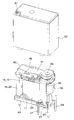
- FIGS. 1 to 3 An embodiment in which a switch according to the present invention is applied to an electromagnetic relay will be described with reference to the accompanying drawings of FIGS.
- the normally open fixed contact terminal 30, the movable contact terminal 40 and the normally closed fixed contact terminal 50 are assembled to the electromagnet body 10.
- the box-shaped case 60 is fitted.
- the shock absorbers 70 and 71 are shown only in FIG.
- the electromagnet body 10 is formed by winding a coil 20 around a cylindrical body portion (not shown) of a spool 13 in which a base portion 11 is integrally formed at a lower end and a flange portion 12 is integrally formed at an upper end.
- the electromagnet main body 10 has an iron core 21 having a substantially T-shaped cross section inserted into the through hole of the cylindrical body portion of the spool 13 from above, and the projecting upper end portion serves as the magnetic pole portion 22, while the projecting lower end.
- the portion 23 is caulked and fixed to the horizontal portion 26 of the yoke 25 having a substantially L-shaped cross section (see FIG. 3).
- the normally open fixed contact terminal 30 has a normally open fixed contact 32 fixed by caulking to a horizontal portion 31 whose upper end is bent in a substantially L shape, and its lower end is press-fitted.
- the protrusion 33 is used.
- the normally open fixed contact terminal 30 is provided with a terminal portion 34 and a press-fitting projection 35 by being bent by extending sideward from the lower edge portion.
- the movable contact terminal 40 is formed by bending a conductive leaf spring into a substantially L shape, having one end as a movable contact piece 41, and a movable contact 42 fixed to the free end thereof by caulking. On the other hand, the other end portion is used as a terminal portion 43.
- the movable contact terminal 40 has a pair of caulking holes, and a movable iron piece 45 is caulked and fixed to the lower surface of the movable contact piece 41.
- the normally closed fixed contact terminal 50 has a normally closed fixed contact 52 fixed by caulking to a horizontal portion 51 whose upper end is bent in a substantially L shape, and its lower end is press-fitted.
- the protrusion 53 is used.
- the normally closed fixed contact terminal 50 is provided with a terminal portion 54 and a press-fitting projection 55 by being bent by extending laterally from the lower end side edge portion thereof.
- the box-shaped case 60 has an outer peripheral shape that can be fitted to the base portion 11 of the electromagnet main body 10, and has a hole 61 at the upper surface corner.
- the shock absorbing material 70 is filled in the gap between the flange portion 12 of the spool 13 and the horizontal portion 31 of the normally open fixed contact terminal 30.
- a shock absorbing material 71 is also filled in the gap between the horizontal portion 51 of the normally closed fixed contact terminal 50 and the ceiling surface of the box-shaped case 60.
- the shock absorbers 70 and 71 do not need to be filled in the entire gap, and may be filled at least in part. For example, of the lower surface of the horizontal portion 31 of the normally open fixed contact terminal 30, only the base portion, only the back surface of the normally open fixed contact 32, or only the front end edge portion may be filled with the shock absorbing material 70. The same applies to the shock absorbing material 71.
- the shock absorbers 70 and 71 may be sheet-like elastic materials that sandwich the front and back surfaces, or may be filled and cured with a curable resin, or a combination of both. Also good.
- the curable resin include an ultraviolet curable resin (for example, Toa Gosei UV-3300), an anaerobic curable resin, and a thermosetting resin.
- the thermosetting resin is a one-component epoxy heat curing. Mold adhesive (for example, EW2020 manufactured by Sumitomo 3M).
- the curable resin does not necessarily need to be liquid, and may be a paste-like curable resin.
- the coil 20 is wound around the cylindrical body portion of the spool 13 in which the coil terminals 27 and 27 are press-fitted into the base portion 11, and the lead wire is entangled with the binding portion 27 a of the coil terminal 27 and soldered.
- the horizontal part of the yoke 25 which inserted the iron core 21 of a cross-sectional substantially T shape into the through-hole of the cylindrical trunk
- the press-fitting protrusions 33 and 35 of the normally open fixed contact terminal 30 are press-fitted and fixed into the press-fitting holes 14 a and 14 b of the base portion 11.
- the yoke 25 is fixed to the vertical portion of the yoke 25 via the crimping hole 44 of the movable contact terminal 40, and the movable iron piece 45 is rotatably supported on the upper edge of the yoke 25.
- the movable contact 42 opposes the normally open fixed contact 32 so that contact / separation is possible.
- the normally closed fixed contact 52 can be brought into and out of contact with the movable contact 42 by press-fitting and fixing the press-fitting protrusions 53 and 55 of the normally closed fixed contact terminal 50 into the press-fitting holes 15 a and 15 b of the base portion 11. opposite.
- the shock absorbing material made of a paste-like thermosetting resin material is filled in the entire gap between the horizontal portion 31 of the normally open fixed contact terminal 30 and the flange portion 12 of the spool 13. Further, an appropriate amount of impact absorbing material 71 made of a paste-like thermosetting resin material is applied to the upper surface of the horizontal portion 51 of the normally closed fixed contact terminal 50.
- thermosetting resin is sealed in the recess formed by the bottom surface of the base portion 11 and the opening edge of the box-shaped case 60. Injected as material (not shown). Then, the shock absorbers 70 and 71 and the sealing material are heated and cured. Next, the hole 61 is heat sealed to complete the assembly operation. According to the present embodiment, since the shock absorbers 70 and 71 and the sealing material are heated and cured simultaneously, there is an advantage that an electromagnetic relay with a low production man-hour and high productivity can be obtained.
- the shock absorbers 70 and 71 and the sealing material need not be cured at the same time.
- the gap between the horizontal portion 31 and the flange portion 12 of the spool 13 is filled with the shock absorber 70 made of an ultraviolet curable resin.
- the impact absorbing material 70 is cured in advance by irradiating with ultraviolet rays.
- an impact absorbing material 71 made of a paste-like thermosetting resin material is applied to the upper surface of the horizontal portion 51, a box-shaped case 60 is fitted to the electromagnet main body 10, a sealing material is injected, and then heated and cured. May be.
- a curable resin can be used in an appropriate place.
- the shock absorbing material 71 when applied to the upper surface of the horizontal portion 51 of the normally closed fixed contact terminal 50, a resin material having a high viscosity is injected and filled from an injection hole (not shown) provided in the case 60. Accordingly, the horizontal portion 51 may be fixedly integrated with the ceiling surface of the box-shaped case 60.
- the operation of the electromagnetic relay will be described.
- the movable contact 42 is biased upward by the spring force of the movable contact piece 41, and the movable contact 42 is in contact with the normally closed fixed contact 52.
- the magnetic pole portion 22 of the iron core 21 attracts the movable iron piece 45, resists the spring force of the movable contact piece 41, and the movable contact 42 contacts the normally open fixed contact 32.
- the impact force of the movable contact 42 is absorbed by the shock absorber 70, and contact bounce is unlikely to occur in the movable contact 42.
- the movable contact 42 contacts the normally closed fixed contact 52 after the movable contact 42 is separated from the normally open fixed contact 32 by the spring force of the movable contact piece 41. Also at this time, the impact force of the movable contact 42 is absorbed by the shock absorber 71, and contact bounce is unlikely to occur at the movable contact.
- the reason why the contact bounce hardly occurs in the movable contact 42 is that when the movable contact 42 comes into contact with the normally open / normally closed fixed contacts 32 and 52, the impact force of the movable contact 42 is absorbed by the shock absorbers 70 and 71. This is considered to be because the normally open / normally closed fixed contacts 32 and 52 are less likely to bend accompanying the movement of the movable contact 42.
- the second embodiment of the switch according to the present invention is applied to a switch as shown in FIG.
- a switch for example, a switch disclosed in Japanese Patent Application Laid-Open No. 2010-40310 can be given. That is, a plunger 83 having an operation portion 82 is assembled in a housing 81 fitted to the base 80 via a coil spring 84 so as to be movable up and down, and the movable contact piece 85 is supported on the base 80 so as to be rotatable. .
- a fixed contact 88 is provided at the free end of the support terminal 87 assembled to the base 80, and an impact absorbing member 89 is filled between the base 80 and the fixed contact 88.
- the movable contact piece 85 provided at the free end of the movable contact piece 85 is brought into contact with the fixed contact 88 of the support terminal 87 by pushing down the operation portion 82 of the plunger 83 and rotating the movable contact piece 85. Touch.
- the impact absorbing material 89 provided on the back surface of the fixed contact 88 absorbs and relaxes the impact force when the movable contact 86 abuts on the fixed contact 88. There is an advantage that contact bounce hardly occurs.
- Example 1 Thermosetting is performed on the entire back surface of the horizontal portion of the normally open fixed contact terminal (opening force (20 cN), contact force (25 cN), fixed terminal angle (+2 degrees upward from the horizontal plane)) of the electromagnetic relay illustrated in FIG.
- a sample was obtained by filling and curing an impact-absorbing material made of a conductive resin (Sumitomo 3M one-part epoxy resin).
- a thermosetting resin (1 mm 3 ) was injected with a dropper between the fixed contact and the spool on the back surface.
- a curing method it was cured by heating in an oven at 100 ° C. for 1 hour.
- the contact bounce time at the time of closing only the normally open fixed contact of the obtained sample was measured 5 times.
- the contact bounce time when the sample was closed averaged 0.05 ms.
- the contact bounce time refers to the time until the voltage between the contacts being measured decreases to several hundred mV or less.
- Example 2 As is clear from the measurement results of Example 1 and Comparative Example 1 described above, it was found that according to Example 1, the contact bounce time at the closing time was significantly shorter than that of Comparative Example 1. [Example 2]
- thermosetting resin one-component epoxy resin
- Example 3 From the measurement results of Example 2 and Comparative Example 2 described above, it was found that the contact bounce time at the time of closing is shortened even if only the base portion of the horizontal portion of the normally open fixed contact terminal is fixed and integrated.
- Example 3 Except that the shock absorber was not provided, the rest was assembled in the same manner as in Example 3 to obtain six samples. Then, an electrical durability test was performed under the same conditions as in Example 3.
- Example 4 From the measurement results of Example 3 and Comparative Example 3 described above, the average contact opening / closing frequency of Example 3 was 1.87 times the average contact opening / closing frequency of Comparative Example 3, and it was confirmed that the electrical durability was high. . [Example 4]
- the operation of the electromagnetic relay according to FIG. 1 was photographed with a high-speed camera, and the operation of the movable contact was visually observed. It was confirmed that when the movable contact abuts the normally open / normally closed fixed contact, the normally open / normally closed fixed contact hardly bends along with the movement of the movable contact, and contact bounce hardly occurs. In addition, it was confirmed that the arc during closing was less likely to occur.
- the electromagnetic relay according to the present invention is not limited to the electromagnetic relay described above.
- the electromagnetic relay having only a normally open fixed contact or only a normally closed fixed contact, and other switches such as a switch causing contact bounce.
- the above may also be applied.
- Electromagnet main body 11 Base part 12: collar part 13: Spool 20: Coil 21: Iron core 25: Yoke 27: Coil terminal 30: Normally open fixed contact terminal 31: Horizontal part 32: Normally open fixed contact 34: Terminal part 40: movable contact terminal 41: movable contact piece 42: movable contact 43: terminal portion 45: movable iron piece 50: normally closed fixed contact terminal 51: horizontal portion 52: normally closed fixed contact 54: terminal portion 60: box-shaped case 70, 71: Shock absorber (intervening member) 80: base 85: movable contact piece 86: movable contact 87: support terminal 88: fixed contact 89: shock absorbing member (intervening member)
Landscapes
- Physics & Mathematics (AREA)
- Electromagnetism (AREA)
- Electromagnets (AREA)
Abstract
La présente invention concerne un commutateur, qui est facilement fabriqué, possède des caractéristiques de fonctionnement uniformes, et pour lequel il y a peu d'occurrences de formation d'arc en raison de rebondissement de contact même durant l'utilisation dans une plage de courant élevé, et un procédé pour sa fabrication. Ainsi, le commutateur comporte : une base (11) ; un boîtier (60) accouplé avec la base (11) ; et un élément constituant fixe unifié avec la base (11) ou le boîtier (60). Le commutateur met un contact mobile (42), qui est prévu sur une pièce de contact mobile (41), en contact avec un contact fixe (52) d'une borne de contact fixe (50) fixée à la base (11) et le sépare de celui-ci. Plus spécifiquement, un élément intervenant (71) qui entre en contacts avec les deux côtés opposés, sur le boîtier (60) et la borne de contact fixe (50), est prévu.
Applications Claiming Priority (2)
| Application Number | Priority Date | Filing Date | Title |
|---|---|---|---|
| JP2012-058245 | 2012-03-15 | ||
| JP2012058245A JP2013191480A (ja) | 2012-03-15 | 2012-03-15 | 開閉器およびその製造方法 |
Publications (1)
| Publication Number | Publication Date |
|---|---|
| WO2013136629A1 true WO2013136629A1 (fr) | 2013-09-19 |
Family
ID=49160582
Family Applications (1)
| Application Number | Title | Priority Date | Filing Date |
|---|---|---|---|
| PCT/JP2012/083664 Ceased WO2013136629A1 (fr) | 2012-03-15 | 2012-12-26 | Commutateur et procédé pour sa fabrication |
Country Status (2)
| Country | Link |
|---|---|
| JP (1) | JP2013191480A (fr) |
| WO (1) | WO2013136629A1 (fr) |
Cited By (1)
| Publication number | Priority date | Publication date | Assignee | Title |
|---|---|---|---|---|
| WO2015087543A1 (fr) * | 2013-12-13 | 2015-06-18 | パナソニックIpマネジメント株式会社 | Relais électromagnétique |
Families Citing this family (1)
| Publication number | Priority date | Publication date | Assignee | Title |
|---|---|---|---|---|
| JP7508774B2 (ja) * | 2019-12-19 | 2024-07-02 | オムロン株式会社 | 電磁継電器 |
Citations (4)
| Publication number | Priority date | Publication date | Assignee | Title |
|---|---|---|---|---|
| JPS61148733A (ja) * | 1984-12-21 | 1986-07-07 | 富士電機株式会社 | 開閉器の緩衝装置 |
| JPS6355829A (ja) * | 1986-08-26 | 1988-03-10 | 松下電工株式会社 | 電磁継電器 |
| JPH0244235U (fr) * | 1988-09-20 | 1990-03-27 | ||
| JPH0527942U (ja) * | 1991-09-24 | 1993-04-09 | 日本電気株式会社 | 電磁リレー |
-
2012
- 2012-03-15 JP JP2012058245A patent/JP2013191480A/ja active Pending
- 2012-12-26 WO PCT/JP2012/083664 patent/WO2013136629A1/fr not_active Ceased
Patent Citations (4)
| Publication number | Priority date | Publication date | Assignee | Title |
|---|---|---|---|---|
| JPS61148733A (ja) * | 1984-12-21 | 1986-07-07 | 富士電機株式会社 | 開閉器の緩衝装置 |
| JPS6355829A (ja) * | 1986-08-26 | 1988-03-10 | 松下電工株式会社 | 電磁継電器 |
| JPH0244235U (fr) * | 1988-09-20 | 1990-03-27 | ||
| JPH0527942U (ja) * | 1991-09-24 | 1993-04-09 | 日本電気株式会社 | 電磁リレー |
Cited By (4)
| Publication number | Priority date | Publication date | Assignee | Title |
|---|---|---|---|---|
| WO2015087543A1 (fr) * | 2013-12-13 | 2015-06-18 | パナソニックIpマネジメント株式会社 | Relais électromagnétique |
| JP2015115248A (ja) * | 2013-12-13 | 2015-06-22 | パナソニックIpマネジメント株式会社 | 電磁リレー |
| US10269516B2 (en) | 2013-12-13 | 2019-04-23 | Panasonic Intellectual Property Management Co., Ltd. | Electromagnetic relay |
| USRE49318E1 (en) | 2013-12-13 | 2022-11-29 | Panasonic Intellectual Property Management Co., Ltd. | Electromagnetic relay |
Also Published As
| Publication number | Publication date |
|---|---|
| JP2013191480A (ja) | 2013-09-26 |
Similar Documents
| Publication | Publication Date | Title |
|---|---|---|
| CN104641441B (zh) | 电磁继电器 | |
| US8198964B2 (en) | Sealed contact device | |
| CN103367042B (zh) | 电磁继电器 | |
| CN103035448B (zh) | 电磁继电器 | |
| JP6258138B2 (ja) | 電磁継電器 | |
| CN1290949A (zh) | 电磁断路器 | |
| US9401256B2 (en) | Electromagnetic relay | |
| JP2019096460A (ja) | 電磁継電器 | |
| JP2002237241A (ja) | 電磁継電器 | |
| CN107251182B (zh) | 触点机构及具备该触点机构的电磁继电器 | |
| US8963660B2 (en) | Electromagnetic relay | |
| CN101283428A (zh) | 继电器 | |
| CN203150486U (zh) | 电磁继电器 | |
| CN104037023B (zh) | 电磁继电器及其制造方法 | |
| JP2012015088A (ja) | 電磁接触器 | |
| JP4476072B2 (ja) | 電磁継電器 | |
| WO2013136629A1 (fr) | Commutateur et procédé pour sa fabrication | |
| CN101283429A (zh) | 继电器 | |
| CN203288514U (zh) | 电子设备的密封结构 | |
| CN115910691A (zh) | 电磁继电器 | |
| CN101283431B (zh) | 继电器 | |
| CN112582210A (zh) | 继电器 | |
| CN212365865U (zh) | 触点装置、电磁继电器和具备电磁继电器的装置 | |
| JP5525672B2 (ja) | 電磁リレーのヨークの構造 | |
| JP7468277B2 (ja) | 電磁継電器 |
Legal Events
| Date | Code | Title | Description |
|---|---|---|---|
| 121 | Ep: the epo has been informed by wipo that ep was designated in this application |
Ref document number: 12870965 Country of ref document: EP Kind code of ref document: A1 |
|
| NENP | Non-entry into the national phase |
Ref country code: DE |
|
| 122 | Ep: pct application non-entry in european phase |
Ref document number: 12870965 Country of ref document: EP Kind code of ref document: A1 |