WO2013136714A1 - Équipement de régulation de l'humidité - Google Patents
Équipement de régulation de l'humidité Download PDFInfo
- Publication number
- WO2013136714A1 WO2013136714A1 PCT/JP2013/001321 JP2013001321W WO2013136714A1 WO 2013136714 A1 WO2013136714 A1 WO 2013136714A1 JP 2013001321 W JP2013001321 W JP 2013001321W WO 2013136714 A1 WO2013136714 A1 WO 2013136714A1
- Authority
- WO
- WIPO (PCT)
- Prior art keywords
- valve
- humidity control
- control circuit
- heat exchanger
- refrigerant
- Prior art date
- Legal status (The legal status is an assumption and is not a legal conclusion. Google has not performed a legal analysis and makes no representation as to the accuracy of the status listed.)
- Ceased
Links
Images




Classifications
-
- F—MECHANICAL ENGINEERING; LIGHTING; HEATING; WEAPONS; BLASTING
- F24—HEATING; RANGES; VENTILATING
- F24F—AIR-CONDITIONING; AIR-HUMIDIFICATION; VENTILATION; USE OF AIR CURRENTS FOR SCREENING
- F24F3/00—Air-conditioning systems in which conditioned primary air is supplied from one or more central stations to distributing units in the rooms or spaces where it may receive secondary treatment; Apparatus specially designed for such systems
- F24F3/12—Air-conditioning systems in which conditioned primary air is supplied from one or more central stations to distributing units in the rooms or spaces where it may receive secondary treatment; Apparatus specially designed for such systems characterised by the treatment of the air otherwise than by heating and cooling
- F24F3/14—Air-conditioning systems in which conditioned primary air is supplied from one or more central stations to distributing units in the rooms or spaces where it may receive secondary treatment; Apparatus specially designed for such systems characterised by the treatment of the air otherwise than by heating and cooling by humidification; by dehumidification
- F24F3/1411—Air-conditioning systems in which conditioned primary air is supplied from one or more central stations to distributing units in the rooms or spaces where it may receive secondary treatment; Apparatus specially designed for such systems characterised by the treatment of the air otherwise than by heating and cooling by humidification; by dehumidification by absorbing or adsorbing water, e.g. using an hygroscopic desiccant
- F24F3/1429—Air-conditioning systems in which conditioned primary air is supplied from one or more central stations to distributing units in the rooms or spaces where it may receive secondary treatment; Apparatus specially designed for such systems characterised by the treatment of the air otherwise than by heating and cooling by humidification; by dehumidification by absorbing or adsorbing water, e.g. using an hygroscopic desiccant alternatively operating a heat exchanger in an absorbing/adsorbing mode and a heat exchanger in a regeneration mode
-
- F—MECHANICAL ENGINEERING; LIGHTING; HEATING; WEAPONS; BLASTING
- F24—HEATING; RANGES; VENTILATING
- F24F—AIR-CONDITIONING; AIR-HUMIDIFICATION; VENTILATION; USE OF AIR CURRENTS FOR SCREENING
- F24F11/00—Control or safety arrangements
- F24F11/0008—Control or safety arrangements for air-humidification
-
- F—MECHANICAL ENGINEERING; LIGHTING; HEATING; WEAPONS; BLASTING
- F25—REFRIGERATION OR COOLING; COMBINED HEATING AND REFRIGERATION SYSTEMS; HEAT PUMP SYSTEMS; MANUFACTURE OR STORAGE OF ICE; LIQUEFACTION SOLIDIFICATION OF GASES
- F25B—REFRIGERATION MACHINES, PLANTS OR SYSTEMS; COMBINED HEATING AND REFRIGERATION SYSTEMS; HEAT PUMP SYSTEMS
- F25B13/00—Compression machines, plants or systems, with reversible cycle
Definitions
- the present invention relates to a humidity control apparatus.
- an air conditioning system in which outdoor air and indoor air are conditioned and the conditioned air is supplied indoors (see, for example, Patent Document 1).
- This air conditioning system has a refrigerant circuit in which a refrigerant is circulated and a refrigeration cycle is performed.
- the refrigerant circuit includes a heat source circuit to which a compressor that compresses the refrigerant is connected, and a plurality of humidity control circuits that are connected in parallel to the heat source circuit via a communication pipe.
- the humidity control circuit is connected with first and second adsorption heat exchangers, an expansion valve, and a four-way switching valve.
- the adsorption heat exchanger is configured by carrying an adsorbent on the surface of the heat exchanger.
- the first port of the four-way selector valve is connected to the discharge side of the compressor of the heat source circuit via the discharge gas communication pipe.
- the second port is connected to the suction side of the compressor of the heat source circuit via the suction gas communication pipe.
- the third port is connected to the gas side end of the first adsorption heat exchanger.
- the fourth port is connected to the gas side end of the second adsorption heat exchanger.
- the four-way switching valve when the four-way switching valve is in the first state in which the first port and the third port are connected and the second port and the fourth port are connected, the high-pressure side of the heat source circuit and the first adsorption heat exchanger are Connecting, the low pressure side of the heat source circuit and the second adsorption heat exchanger are connected.
- the high-pressure refrigerant compressed by the compressor is shunted to each humidity control circuit and then condensed by the first adsorption heat exchanger.
- the condensed refrigerant is depressurized by the expansion valve and then evaporated by the second adsorption heat exchanger.
- the evaporated refrigerant joins in the heat source circuit and is sucked into the compressor again.
- each humidity control circuit the adsorbent of the first adsorption heat exchanger is heated and regenerated by the refrigerant, while the adsorbent of the second adsorption heat exchanger is cooled by the refrigerant, and the adsorbent is in the air. Moisture is adsorbed.
- the four-way switching valve when the four-way switching valve is in the second state in which the first port and the fourth port are connected and the second port and the third port are connected, the high-pressure side of the heat source circuit and the second adsorption heat exchanger are connected. The low-pressure side of the heat source circuit and the first adsorption heat exchanger are connected.
- the high-pressure refrigerant compressed by the compressor is shunted to each humidity control circuit and then condensed by the second adsorption heat exchanger.
- the condensed refrigerant is depressurized by the expansion valve and then evaporated by the first adsorption heat exchanger.
- the evaporated refrigerant joins in the heat source circuit and is sucked into the compressor again.
- each humidity control circuit the adsorbent of the second adsorption heat exchanger is heated and regenerated by the refrigerant, while the adsorbent of the first adsorption heat exchanger is cooled by the refrigerant, and the adsorbent is in the air. Moisture is adsorbed.
- the third port of the four-way switching valve and the gas side end of the first adsorption heat exchanger A high-pressure refrigerant circulates in the refrigerant pipe connecting the two.
- the second port and the third port are connected, and the gas side end of the first adsorption heat exchanger is connected to the intake gas communication pipe. Therefore, the high-pressure refrigerant remaining in the refrigerant pipe before switching the four-way switching valve flows suddenly toward the intake gas communication pipe when the four-way switching valve is switched, and the equalized sound at this time is communicated. It will propagate to the piping and increase.
- the present invention has been made in view of this point, and an object of the present invention is to reduce the switching sound that occurs when the pressure difference in the humidity control circuit equalizes by switching the four-way switching valve. .
- the present invention includes a heat source circuit (60) having a compressor (33) for compressing a refrigerant, an adsorption heat exchanger (31, 32) carrying an adsorbent, and a four-way switching valve (34 And a humidity control circuit (20) connected to the heat source circuit (60) via a communication pipe (11, 12), and switching the four-way switching valve (34),
- a heat source circuit 60
- a compressor 33
- adsorption heat exchanger 31, 32
- a four-way switching valve 34
- a humidity control circuit (20) connected to the heat source circuit (60) via a communication pipe (11, 12), and switching the four-way switching valve (34)
- An adsorption operation in which the heat exchanger (31, 32) serves as an evaporator to adsorb moisture in the air to the adsorbent, and the adsorption heat exchanger (31, 32) serves as a condenser to remove moisture from the adsorbent.
- the following solution
- the first invention is provided with a differential pressure reducing mechanism (40) for reducing a high / low differential pressure between the high pressure side and the low pressure side of the humidity control circuit (20) before switching the four-way switching valve (34). It is characterized by having.
- the differential pressure reduction mechanism (40) reduces the high / low differential pressure between the high pressure side and the low pressure side of the humidity control circuit (20). .
- the four-way switching valve (34) when the four-way switching valve (34) is switched, the switching sound generated when the pressure difference between the high pressure side and the low pressure side of the humidity control circuit (20) is equalized is connected to the communication pipe ( 11,12) can be suppressed.
- the adsorption heat exchanger (31, 32) becomes a condenser and performs a regeneration operation to desorb moisture from the adsorbent
- the four-way switching valve (34) and the adsorption heat exchanger (31, 32) High-pressure refrigerant circulates in the refrigerant pipe (25) connecting the two.
- the four-way switching valve (34) when the four-way switching valve (34) is switched and the adsorption heat exchanger (31, 32) becomes an evaporator and performs an adsorption operation for adsorbing moisture in the air to the adsorbent, the four-way switching valve (34 ),
- the high-pressure refrigerant remaining in the refrigerant pipe (25) suddenly flows toward the low-pressure side connecting pipe (12) when the four-way selector valve (34) is switched. Pressure noise will propagate to the low-pressure side connecting pipe (12) and increase.
- the pressure difference of the humidity control circuit (20) is reduced by the differential pressure reduction mechanism (40) before the four-way switching valve (34) is switched.
- the differential pressure reduction mechanism (40) has a valve mechanism (45) connected to at least the outflow pipe (24) of the inflow pipe (23) and the outflow pipe (24) of the humidity control circuit (20).
- the valve mechanism (45) includes an on-off valve (46) that shuts off the refrigerant flow when the valve mechanism (45) is closed, or an electric valve (47) whose opening degree can be adjusted.
- At least the outflow pipe (24) of the inflow pipe (23) and the outflow pipe (24) of the humidity control circuit (20) is configured with an on-off valve (46) or an electric valve (47).
- Each valve mechanism (45) is connected.
- the circulation of the refrigerant in the inflow piping (23) and the outflow piping (24) is interrupted by closing the on-off valve (46) or reducing the opening of the motor operated valve (47).
- the on-off valve (46) is closed, or the opening of the motor-operated valve (47) is reduced, so that the humidity control circuit (20)
- the refrigerant in the refrigerant pipe (25) connecting the four-way selector valve (34) and the adsorption heat exchanger (31, 32) is made an intermediate pressure to reduce the high and low differential pressure by blocking the circulation of the refrigerant inside be able to.
- the amount of refrigerant circulating in the humidity control circuit (20) is small, so the high-pressure refrigerant flows into the refrigerant pipe (25) before switching the four-way switching valve (34). Even if it is not shut off, the amount of refrigerant remaining in the refrigerant pipe (25) does not increase so much. Therefore, in a humidity control device that performs low-load operation, if the differential pressure reduction mechanism (40) is provided only in the outflow pipe (24) of the humidity control circuit (20), the high and low differential pressures of the humidity control circuit (20) can be reduced. It is possible to reduce the switching sound generated when the pressure is equalized.
- a pipe (24) to which the valve mechanism (45) is connected is connected to a bypass pipe (bypassing the valve mechanism (45)). 41) is connected,
- the differential pressure reduction mechanism (40) has a pressure reducing valve (42) connected to the bypass pipe (41) and having an adjustable opening.
- the pressure reducing valve (42) is configured to gradually increase the opening degree after switching the four-way switching valve (34) and before opening the valve mechanism (45). It is characterized by being configured to reduce the differential pressure.
- the valve mechanism (45) is bypassed to the pipe (24) to which the valve mechanism (45) is connected among the inflow pipe (23) and the outflow pipe (24) of the humidity control circuit (20).
- the bypass pipes (41) are connected to each other.
- a pressure reducing valve (42) whose opening degree can be adjusted is connected to the bypass pipe (41). After switching the four-way selector valve (34) and before opening the valve mechanism (45), gradually increase the opening of the pressure reducing valve (42) to reduce the differential pressure across the valve mechanism (45). Decrease.
- the pressure equalization control before and after the valve mechanism (45) can be performed by the pressure reducing valve (42), and when the valve mechanism (45) is opened. Switching noise can be reduced by suppressing rapid pressure fluctuations.
- the differential pressure reducing mechanism (40) reduces the high / low differential pressure of the humidity control circuit (20).
- the refrigerant can be prevented from flowing rapidly toward the low-pressure side connecting pipe (12).
- the switching sound produced when the pressure difference of the humidity control circuit (20) equalizes can be reduced.
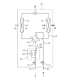
- FIG. 1 is a piping diagram showing a configuration of a refrigerant circuit of a humidity control apparatus according to Embodiment 1 of the present invention, and shows a first operation.
- FIG. 2 is a piping system diagram showing the configuration of the refrigerant circuit of the humidity control apparatus, and shows the second operation.
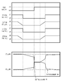
- FIG. 3 is a timing chart showing the switching timing of the four-way switching valve, the on-off valve, and the pressure reducing valve, and a graph showing the pressure fluctuation of the high / low differential pressure of the humidity control circuit at the switching timing.
- FIG. 4 is a piping diagram illustrating a humidity control circuit of the humidity control apparatus according to the second embodiment.
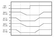
- FIG. 5 is a timing chart showing the switching timing of the four-way switching valve, the electric valve, and the pressure reducing valve.
- FIG. 6 is a piping diagram illustrating a humidity control circuit of the humidity control apparatus according to the third embodiment.
- FIG. 7 is a piping diagram illustrating a humidity control circuit of the humidity control apparatus according to the fourth embodiment.
- FIG. 1 is a piping system diagram showing a configuration of a refrigerant circuit of a humidity control apparatus according to Embodiment 1 of the present invention.
- the humidity controller (1) includes a refrigerant circuit (10) in which a refrigerant circulates and a vapor compression refrigeration cycle is performed.
- the refrigerant circuit (10) includes a heat source circuit (60) and three humidity control circuits (20 connected in parallel to the heat source circuit (60) via the high-pressure side communication pipe (11) and the low-pressure side communication pipe (12). ).
- the number of humidity control circuits (20) is merely an example.
- the compressor (33), the high-pressure side shut-off valve (61), and the low-pressure side shut-off valve (62) are connected to the heat source circuit (60).
- the compressor (33) is a so-called inverter type compressor in which the rotation speed of the motor (that is, the compressor capacity) is variable. Further, the compressor (33) is constituted by, for example, a scroll type compressor.
- the humidity control circuit (20) adjusts the humidity of the taken outdoor air (OA) and supplies it to the room.
- the humidity control circuit (20) is installed on the back of the ceiling, for example.
- a first adsorption heat exchanger (31), an electric expansion valve (35), and a second adsorption heat exchanger (32) are sequentially connected to the humidity control circuit (20).
- the first adsorption heat exchanger (31) and the second adsorption heat exchanger (32) carry an adsorbent on the surface and adsorb and desorb moisture in the air.
- the electric expansion valve (35) is an electronic expansion valve whose opening degree is adjustable. Further, a four-way switching valve (34) for switching the refrigerant flow direction is connected to the humidity control circuit (20).
- the four-way switching valve (34) has first to fourth ports.
- the first port of the four-way selector valve (34) is connected to the inflow pipe (23) of the humidity control circuit (20).
- a valve mechanism (45) constituting a differential pressure reducing mechanism (40) and a high-pressure side shut-off valve (21) are connected to the inflow pipe (23).
- the high-pressure side shut-off valve (61) of the heat source circuit (60) and the high-pressure side shut-off valve (21) of the humidity control circuit (20) are connected via a high-pressure side connecting pipe (11). Thereby, the humidity control circuit (20) is connected with the high voltage
- the second port of the four-way selector valve (34) is connected to the outflow pipe (24) of the humidity control circuit (20).
- a valve mechanism (45) and a low-pressure side closing valve (22) are connected to the outflow pipe (24).
- the low pressure side closing valve (62) of the heat source circuit (60) and the low pressure side closing valve (22) of the humidity control circuit (20) are connected via a low pressure side communication pipe (12).
- the humidity control circuit (20) is connected with the low voltage
- the third port of the four-way switching valve (34) is connected to one end of the first adsorption heat exchanger (31), and the fourth port of the four-way switching valve (34) is connected to the second adsorption heat exchanger (32). ) Is connected to one end.
- the four-way selector valve (34) has a first state in which the first port and the third port communicate with each other and the second port and the fourth port communicate with each other, and the first port and the fourth port communicate with each other. It is possible to switch to a second state (see FIG. 2) in which the second port and the third port communicate with each other.
- the four-way switching valve (34) in the first state shown in FIG. 1 connects the high pressure side of the heat source circuit (60) and one end of the first adsorption heat exchanger (31) to connect the low pressure of the heat source circuit (60).
- the side and one end of the second adsorption heat exchanger (32) are connected.
- the four-way selector valve (34) in the second state shown in FIG. 2 connects the high pressure side of the heat source circuit (60) and the second adsorption heat exchanger (32) to the low pressure side of the heat source circuit (60). Connect the first adsorption heat exchanger (31).
- the valve mechanism (45) is composed of an on-off valve (46) that shuts off the refrigerant flow when the valve mechanism (45) is closed.
- a bypass pipe (41) for bypassing the on-off valve (46) is connected to the inflow pipe (23) and the outflow pipe (24) of the humidity control circuit (20).
- a pressure reducing valve (42) whose opening degree can be adjusted is connected to the bypass pipe (41).
- the pressure reducing valve (42) is a small diameter type valve having a small nominal diameter.
- the differential pressure reducing mechanism (40) includes a valve mechanism (45) and a pressure reducing valve (42).
- dehumidification ventilation operation and humidification ventilation operation are selectively performed.
- the humidity control circuit (20) during dehumidification ventilation operation or humidification ventilation operation adjusts the humidity of the taken outdoor air (OA) and then supplies it to the room as supply air (SA).
- SA taken outdoor air
- RA room air
- EA exhaust air
- ⁇ Dehumidification ventilation operation> In the humidity control circuit (20) during the dehumidifying ventilation operation, the first operation and the second operation are alternately repeated at a predetermined time interval (for example, every 3 minutes).
- the outdoor air (OA) is taken in as the first air from the outside air suction port
- the indoor air (RA) is taken in as the second air from the inside air suction port.
- the four-way selector valve (34) is set to the first state (the state shown in FIG. 1), and the first adsorption heat exchanger (31) serves as a condenser.
- the two-adsorption heat exchanger (32) serves as an evaporator.
- the first air taken in from the outside air inlet passes through the second adsorption heat exchanger (32).
- the second adsorption heat exchanger (32) an adsorption operation is performed in which moisture in the first air is adsorbed by the adsorbent, and the heat of adsorption generated at that time is absorbed by the refrigerant.
- the supply air (SA) dehumidified by the second adsorption heat exchanger (32) is supplied into the room through the air supply port.
- the indoor air (RA) (second air) taken in from the inside air suction port passes through the first adsorption heat exchanger (31).
- the first adsorption heat exchanger (31) a regeneration operation is performed in which moisture is desorbed from the adsorbent heated by the refrigerant, and the desorbed moisture is imparted to the second air.
- Exhaust air (EA) to which moisture has been given by the first adsorption heat exchanger (31) is discharged to the outside through the exhaust port.
- the second operation of the dehumidifying ventilation operation will be described.
- the four-way switching valve (34) In order to perform the second operation in the refrigerant circuit (10), it is necessary to switch the four-way switching valve (34) from the first state to the second state (the state shown in FIG. 2).
- the on-off valve (46) before switching the four-way switching valve (34), the on-off valve (46) is closed to block the flow of refrigerant in the humidity control circuit (20).
- the pressure reducing valve (42) and the on-off valve (46) are closed.
- the four-way switching valve (34) is switched from the first state to the second state, and the inside of the humidity control circuit (20) is set to an intermediate pressure.
- the four-way switching valve (34) is set to the second state (the state shown in FIG. 2), and the first adsorption heat exchanger (31) is connected to the evaporator.
- the second adsorption heat exchanger (32) becomes a condenser.
- the opening degree of the pressure reducing valve (42) is gradually increased. Enlarge. Thereby, the differential pressure before and after the on-off valve (46) is reduced. Thereafter, the on-off valve (46) is opened. Thereby, a sudden pressure fluctuation when the on-off valve (46) is opened can be suppressed.
- the pressure difference between the high pressure side and the low pressure side of the humidity control circuit (20) is reduced by the pressure reducing valve (42) and the on-off valve (46).
- the four-way switching valve (34) is switched, it is possible to prevent the switching sound generated when the pressure difference in the humidity control circuit (20) is equalized from propagating to the low-pressure side connecting pipe (12).
- the four-way selector valve (34) when the four-way selector valve (34) is in the first state, the high-pressure refrigerant flows through the refrigerant pipe (25) connecting the four-way selector valve (34) and the first adsorption heat exchanger (31). ing. Therefore, when the four-way switching valve (34) is switched and the first adsorption heat exchanger (31) becomes an evaporator and performs an adsorption operation for adsorbing moisture in the air to the adsorbent, the four-way switching valve (34) ), The high-pressure refrigerant remaining in the refrigerant pipe (25) suddenly flows toward the low-pressure side connecting pipe (12) when the four-way selector valve (34) is switched. Pressure noise will propagate to the low-pressure side connecting pipe (12) and increase.
- the pressure difference in the humidity control circuit (20) is reduced by the pressure reducing valve (42) and the on-off valve (46).
- the refrigerant in the refrigerant pipe (25) can be set to an intermediate pressure, and the refrigerant can be prevented from flowing rapidly toward the low-pressure side connecting pipe (12). Thereby, the switching sound produced when the pressure difference of the humidity control circuit (20) equalizes can be reduced.
- the first air taken in from the outside air inlet passes through the first adsorption heat exchanger (31).
- the first adsorption heat exchanger (31) an adsorption operation is performed in which moisture in the first air is adsorbed by the adsorbent, and the heat of adsorption generated at that time is absorbed by the refrigerant.
- the first air dehumidified by the first adsorption heat exchanger (31) is supplied into the room through the air supply port.
- the second air taken in from the inside air suction port passes through the second adsorption heat exchanger (32).
- the second adsorption heat exchanger (32) a regeneration operation is performed in which moisture is desorbed from the adsorbent heated by the refrigerant, and the desorbed moisture is imparted to the second air.
- the second air given moisture by the second adsorption heat exchanger (32) is discharged to the outside through the exhaust port.
- ⁇ Humidified ventilation operation In the humidity control circuit (20) during the humidification ventilation operation, the first operation and the second operation are alternately repeated at a predetermined time interval (for example, every 4 minutes).
- the outdoor air (OA) is taken in as the second air from the outside air suction port
- the indoor air (RA) is taken in as the first air from the inside air suction port.
- the four-way selector valve (34) is set to the first state (the state shown in FIG. 1), and the first adsorption heat exchanger (31) serves as a condenser.
- the two-adsorption heat exchanger (32) serves as an evaporator.
- the first air taken in from the inside air suction port passes through the second adsorption heat exchanger (32).
- the second adsorption heat exchanger (32) an adsorption operation is performed in which moisture in the first air is adsorbed by the adsorbent, and the heat of adsorption generated at that time is absorbed by the refrigerant.
- the first air deprived of moisture by the second adsorption heat exchanger (32) is discharged to the outside through the exhaust port.
- the second air taken in from the outside air suction port passes through the first adsorption heat exchanger (31).
- the first adsorption heat exchanger (31) a regeneration operation is performed in which moisture is desorbed from the adsorbent heated by the refrigerant, and the desorbed moisture is imparted to the second air.
- the second air humidified by the first adsorption heat exchanger (31) is supplied into the room through the air supply port.
- the four-way selector valve (34) is set to the second state (the state shown in FIG. 2), and the first adsorption heat exchanger (31) serves as the evaporator.
- the two-adsorption heat exchanger (32) serves as a condenser.
- the pressure reducing valve (42) and the on-off valve (46) are connected to the high pressure side and the low pressure side of the humidity control circuit (20) as described in the dehumidifying ventilation operation. Control is performed to reduce the differential pressure level.
- the first air taken in from the inside air suction port passes through the first adsorption heat exchanger (31).
- the first adsorption heat exchanger (31) an adsorption operation is performed in which moisture in the first air is adsorbed by the adsorbent, and the heat of adsorption generated at that time is absorbed by the refrigerant.
- the first air deprived of moisture by the first adsorption heat exchanger (31) is discharged to the outside through the exhaust port.
- the second air taken in from the outside air suction port passes through the second adsorption heat exchanger (32).
- the second adsorption heat exchanger (32) a regeneration operation is performed in which moisture is desorbed from the adsorbent heated by the refrigerant, and the desorbed moisture is imparted to the second air.
- the second air humidified by the second adsorption heat exchanger (32) is supplied into the room through the air supply port.
- the on-off valve (46) is closed and the humidity control circuit (20) is closed.
- the circulation of the refrigerant is cut off. Accordingly, the refrigerant in the refrigerant pipe (25) connecting the four-way switching valve (34) and the first and second adsorption heat exchangers (31, 32) is set to an intermediate pressure, and the high pressure of the humidity control circuit (20). High and low differential pressures between the side and the low pressure side can be reduced.
- the opening degree of the pressure reducing valve (42) is gradually increased to reduce the differential pressure across the on-off valve (46). As a result, it is possible to suppress a sudden pressure fluctuation when the on-off valve (46) is opened and to reduce the switching sound.
- FIG. 4 is a piping diagram illustrating a humidity control circuit of the humidity control apparatus according to the second embodiment. Since the difference from the first embodiment is that an electric valve (47) is provided instead of the on-off valve (46), the same parts as those in the first embodiment are denoted by the same reference numerals, and only the differences are described below. explain.
- a valve mechanism (45) is connected to the inflow pipe (23) and the outflow pipe (24) of the humidity control circuit (20).
- the valve mechanism (45) is composed of an electric valve (47) whose opening degree can be adjusted.
- the electric valve (47) is a large-diameter type valve having a large nominal diameter.
- a bypass pipe (41) for bypassing the on-off valve (46) is connected to the inflow pipe (23) and the outflow pipe (24) of the humidity control circuit (20).
- a pressure reducing valve (42) whose opening degree can be adjusted is connected to the bypass pipe (41).
- the pressure reducing valve (42) is a small-diameter type valve having a smaller nominal diameter than the motor-operated valve (47).
- FIG. 5 is a timing chart showing the switching timing of the four-way switching valve, the electric valve, and the pressure reducing valve. As shown in FIG. 5, before switching the four-way selector valve (34), the motor-operated valve (47) is closed to block the refrigerant flow in the humidity control circuit (20).
- the opening degree of the pressure reducing valve (42) and the motor operated valve (47) is gradually reduced.
- the four-way switching valve (34) is switched from the first state to the second state, and the humidity control circuit (20) is set to an intermediate pressure.
- the four-way switching valve (34) is set to the second state, and the first adsorption heat exchanger (31) serves as an evaporator to perform the second adsorption heat exchange.
- the vessel (32) becomes a condenser.
- the opening degree of the pressure reducing valve (42) is gradually increased. Thereby, the differential pressure before and after the electric valve (47) is reduced. Thereafter, the opening degree of the motor-operated valve (47) is gradually increased to be opened. Thereby, rapid pressure fluctuation when the motor-operated valve (47) is opened can be suppressed.
- FIG. 6 is a piping diagram illustrating a humidity control circuit of the humidity control apparatus according to the third embodiment.
- a valve mechanism (45) is connected to the inflow pipe (23) and the outflow pipe (24) of the humidity control circuit (20).
- the valve mechanism (45) is composed of an electric valve (47) whose opening degree can be adjusted.
- the electric valve (47) is a large-diameter type valve having a large nominal diameter.
- the opening degree of the motor-operated valve (47) is gradually decreased to close it, and the refrigerant flow in the humidity control circuit (20) is shut off.
- the high / low differential pressure between the high pressure side and low pressure side of the humidity control circuit (20) is reduced, and the high / low differential pressure of the humidity control circuit (20) equalizes when the four-way selector valve (34) is switched. It is possible to suppress the switching sound generated at this time from propagating to the low-pressure side connecting pipe (12).
- the differential pressure reduction mechanism (40) is configured using only the large-diameter motor-operated valve (47), there is no need to provide a bypass pipe (41) or a pressure reducing valve (42). , Can reduce the cost.
- FIG. 7 is a piping diagram illustrating a humidity control circuit of the humidity control apparatus according to the fourth embodiment. Since the difference from the first embodiment is that the valve mechanism (45) is provided only in the outflow pipe (24), the same parts as those in the first embodiment are denoted by the same reference numerals, and only the differences will be described. To do.
- a valve mechanism (45) is connected to the outflow pipe (24) of the humidity control circuit (20).
- the valve mechanism (45) includes an on-off valve (46) that shuts off the refrigerant flow when the valve mechanism (45) is closed.
- a bypass pipe (41) for bypassing the on-off valve (46) is connected to the outflow pipe (24).
- a pressure reducing valve (42) whose opening degree can be adjusted is connected to the bypass pipe (41).
- the pressure reducing valve (42) is a small diameter type valve having a small nominal diameter.
- the differential pressure reducing mechanism (40) includes a valve mechanism (45) and a pressure reducing valve (42).
- a differential pressure reduction mechanism (40) is provided only in the outflow pipe (24) of the humidity control circuit (20), the differential pressure level of the humidity control circuit (20) It is possible to reduce the switching sound that occurs when pressure equalizes.
- the four-way switching valve (34) and the first and second adsorptions The amount of refrigerant remaining in the refrigerant pipe (25) connecting the heat exchanger (31, 32) is also increased. Therefore, before switching the four-way selector valve (34), the on-off valve (46) is closed and the refrigerant flow in the humidity control circuit (20) is shut off, so that the refrigerant in the refrigerant pipe (25) is intermediate. It is necessary to make pressure.
- the amount of refrigerant circulating in the humidity control circuit (20) is small, so the high-pressure refrigerant flows into the refrigerant pipe (25) before switching the four-way selector valve (34). Even without shutting off the refrigerant, the amount of refrigerant remaining in the refrigerant pipe (25) does not increase so much.
- the differential pressure reduction mechanism (40) is provided only in the outflow pipe (24), and before the four-way selector valve (34) is switched, the outflow pipe (24) The on-off valve (46) connected to is closed.
- the opening of the pressure reducing valve (42) is gradually increased to reduce the differential pressure across the on-off valve (46). As a result, it is possible to suppress a sudden pressure fluctuation when the on-off valve (46) is opened and to reduce the switching sound.
- the mode in which the differential pressure reduction mechanism (40) is configured using the on-off valve (46) and the pressure reducing valve (42) has been described.
- the present invention is not limited to this mode.
- the differential pressure reduction mechanism (40) may be configured using an electric valve (47) and a pressure reducing valve (42).
- the present invention is extremely useful because it provides a highly practical effect that the switching sound generated when the four-way switching valve is switched to equalize the level differential pressure of the humidity control circuit can be reduced. Industrial applicability is high.
- Humidity control device 1 Humidity control device 11 High pressure side connection piping 12 Low pressure side connection piping 20 Humidity control circuit 23 Inflow piping 24 Outflow piping 31 First adsorption heat exchanger 32 Second adsorption heat exchanger 33 Compressor 34 Four-way switching valve 40 Differential pressure reduction Mechanism 41 Bypass piping 42 Pressure reducing valve 45 Valve mechanism 46 On-off valve 47 Motorized valve 60 Heat source circuit
Landscapes
- Engineering & Computer Science (AREA)
- Chemical & Material Sciences (AREA)
- Combustion & Propulsion (AREA)
- Mechanical Engineering (AREA)
- General Engineering & Computer Science (AREA)
- Central Air Conditioning (AREA)
- Drying Of Gases (AREA)
- Air Conditioning Control Device (AREA)
- Compression-Type Refrigeration Machines With Reversible Cycles (AREA)
Priority Applications (2)
| Application Number | Priority Date | Filing Date | Title |
|---|---|---|---|
| CN201380013892.2A CN104246382B (zh) | 2012-03-14 | 2013-03-04 | 调湿装置 |
| US14/384,817 US9441844B2 (en) | 2012-03-14 | 2013-03-04 | Humidity controller |
Applications Claiming Priority (2)
| Application Number | Priority Date | Filing Date | Title |
|---|---|---|---|
| JP2012057780 | 2012-03-14 | ||
| JP2012-057780 | 2012-03-14 |
Publications (1)
| Publication Number | Publication Date |
|---|---|
| WO2013136714A1 true WO2013136714A1 (fr) | 2013-09-19 |
Family
ID=49160650
Family Applications (1)
| Application Number | Title | Priority Date | Filing Date |
|---|---|---|---|
| PCT/JP2013/001321 Ceased WO2013136714A1 (fr) | 2012-03-14 | 2013-03-04 | Équipement de régulation de l'humidité |
Country Status (4)
| Country | Link |
|---|---|
| US (1) | US9441844B2 (fr) |
| JP (1) | JP5447705B2 (fr) |
| CN (1) | CN104246382B (fr) |
| WO (1) | WO2013136714A1 (fr) |
Cited By (1)
| Publication number | Priority date | Publication date | Assignee | Title |
|---|---|---|---|---|
| CN107106975A (zh) * | 2015-03-10 | 2017-08-29 | 三菱电机株式会社 | 除湿装置 |
Families Citing this family (3)
| Publication number | Priority date | Publication date | Assignee | Title |
|---|---|---|---|---|
| DE102015215253A1 (de) * | 2015-08-11 | 2017-02-16 | Bayerische Motoren Werke Aktiengesellschaft | Kühlvorrichtung für Energiespeicher |
| EP3453981B1 (fr) * | 2016-06-27 | 2021-09-15 | Daikin Industries, Ltd. | Dispositif de régulation d'humidité |
| CN107121996B (zh) * | 2017-07-04 | 2022-07-01 | 南京信息工程大学 | 一种恒温恒湿控制装置及控制方法 |
Citations (4)
| Publication number | Priority date | Publication date | Assignee | Title |
|---|---|---|---|---|
| JPH03260561A (ja) * | 1990-03-09 | 1991-11-20 | Hitachi Ltd | 空気調和機 |
| JP2005283041A (ja) * | 2004-03-31 | 2005-10-13 | Daikin Ind Ltd | 調湿装置 |
| JP2005291535A (ja) * | 2004-03-31 | 2005-10-20 | Daikin Ind Ltd | 調湿装置 |
| JP2009109096A (ja) * | 2007-10-31 | 2009-05-21 | Daikin Ind Ltd | 調湿装置 |
Family Cites Families (14)
| Publication number | Priority date | Publication date | Assignee | Title |
|---|---|---|---|---|
| KR900005979B1 (ko) * | 1985-08-22 | 1990-08-18 | 미쓰비시 덴끼 가부시기가이샤 | 공기조화장치 |
| JP2902853B2 (ja) * | 1992-04-27 | 1999-06-07 | 三洋電機株式会社 | 空気調和機 |
| JPH1047812A (ja) * | 1996-08-06 | 1998-02-20 | Saginomiya Seisakusho Inc | 弁制御方法及び冷凍サイクルの制御方法 |
| JP4250466B2 (ja) * | 2003-06-30 | 2009-04-08 | キヤノン株式会社 | 画像処理装置、画像処理方法、その記録媒体およびプログラム |
| JP3668763B2 (ja) * | 2003-10-09 | 2005-07-06 | ダイキン工業株式会社 | 空気調和装置 |
| US7886556B2 (en) | 2004-03-31 | 2011-02-15 | Daikin Industries, Ltd. | Air conditioning system |
| JP3711999B2 (ja) * | 2004-03-31 | 2005-11-02 | ダイキン工業株式会社 | 調湿装置 |
| JP3742864B2 (ja) | 2004-03-31 | 2006-02-08 | ダイキン工業株式会社 | 空気調和システム |
| JP3861902B2 (ja) * | 2004-09-09 | 2006-12-27 | ダイキン工業株式会社 | 調湿装置 |
| JP4052319B2 (ja) * | 2005-05-24 | 2008-02-27 | ダイキン工業株式会社 | 空調システム |
| JP3995007B2 (ja) * | 2005-05-30 | 2007-10-24 | ダイキン工業株式会社 | 調湿装置 |
| JP3992051B2 (ja) * | 2005-05-30 | 2007-10-17 | ダイキン工業株式会社 | 空調システム |
| CN100386580C (zh) * | 2006-04-11 | 2008-05-07 | 珠海格力电器股份有限公司 | 一种热泵空调系统及其蒸气喷射控制装置和控制方法 |
| JP5018402B2 (ja) * | 2007-10-31 | 2012-09-05 | ダイキン工業株式会社 | 調湿装置 |
-
2013
- 2013-03-04 WO PCT/JP2013/001321 patent/WO2013136714A1/fr not_active Ceased
- 2013-03-04 CN CN201380013892.2A patent/CN104246382B/zh not_active Expired - Fee Related
- 2013-03-04 JP JP2013041568A patent/JP5447705B2/ja not_active Expired - Fee Related
- 2013-03-04 US US14/384,817 patent/US9441844B2/en not_active Expired - Fee Related
Patent Citations (4)
| Publication number | Priority date | Publication date | Assignee | Title |
|---|---|---|---|---|
| JPH03260561A (ja) * | 1990-03-09 | 1991-11-20 | Hitachi Ltd | 空気調和機 |
| JP2005283041A (ja) * | 2004-03-31 | 2005-10-13 | Daikin Ind Ltd | 調湿装置 |
| JP2005291535A (ja) * | 2004-03-31 | 2005-10-20 | Daikin Ind Ltd | 調湿装置 |
| JP2009109096A (ja) * | 2007-10-31 | 2009-05-21 | Daikin Ind Ltd | 調湿装置 |
Cited By (1)
| Publication number | Priority date | Publication date | Assignee | Title |
|---|---|---|---|---|
| CN107106975A (zh) * | 2015-03-10 | 2017-08-29 | 三菱电机株式会社 | 除湿装置 |
Also Published As
| Publication number | Publication date |
|---|---|
| CN104246382A (zh) | 2014-12-24 |
| US20150027680A1 (en) | 2015-01-29 |
| JP2013217633A (ja) | 2013-10-24 |
| US9441844B2 (en) | 2016-09-13 |
| JP5447705B2 (ja) | 2014-03-19 |
| CN104246382B (zh) | 2017-03-08 |
Similar Documents
| Publication | Publication Date | Title |
|---|---|---|
| JP4466774B2 (ja) | 調湿装置 | |
| CN203874648U (zh) | 除湿装置 | |
| US20230022397A1 (en) | Air quality adjustment system | |
| CN100432554C (zh) | 空气调节装置 | |
| CN103221752B (zh) | 空气调节系统和调湿装置 | |
| JP5962201B2 (ja) | 空調システム | |
| WO2005036061A1 (fr) | Systeme d'air conditionne | |
| KR101667979B1 (ko) | 제습 및 가습 기능을 갖는 공기조화기와 이를 이용한 제습냉방 및 가습난방 방법 | |
| CN109312939B (zh) | 调湿装置 | |
| JP5218135B2 (ja) | 調湿装置 | |
| JP5447705B2 (ja) | 調湿装置 | |
| JP5109590B2 (ja) | 調湿装置 | |
| WO2005095868A1 (fr) | Dispositif de conditionnement d'humidité | |
| KR101973648B1 (ko) | 환기장치의 제어방법 | |
| JP2015048982A (ja) | ドライルーム用の除湿システム | |
| JP7475851B2 (ja) | 除湿装置 | |
| JP2013190177A (ja) | 調湿装置 | |
| JP2002022205A (ja) | 空調システム | |
| KR101665936B1 (ko) | 주거용 냉난방제습장치와 이를 이용한 제습냉방 및 가습난방 방법 | |
| JP2010127522A (ja) | 空調システム | |
| JP2020012603A (ja) | 空気調和システム | |
| JP2009109151A (ja) | 調湿装置 | |
| JP2015068599A (ja) | 除湿システム | |
| JP2010084970A (ja) | 空調システムおよび熱交換ユニット | |
| JP2010078246A (ja) | 空調システム |
Legal Events
| Date | Code | Title | Description |
|---|---|---|---|
| 121 | Ep: the epo has been informed by wipo that ep was designated in this application |
Ref document number: 13761340 Country of ref document: EP Kind code of ref document: A1 |
|
| WWE | Wipo information: entry into national phase |
Ref document number: 14384817 Country of ref document: US |
|
| NENP | Non-entry into the national phase |
Ref country code: DE |
|
| 122 | Ep: pct application non-entry in european phase |
Ref document number: 13761340 Country of ref document: EP Kind code of ref document: A1 |