WO2013136734A1 - Système de détartrage - Google Patents
Système de détartrage Download PDFInfo
- Publication number
- WO2013136734A1 WO2013136734A1 PCT/JP2013/001456 JP2013001456W WO2013136734A1 WO 2013136734 A1 WO2013136734 A1 WO 2013136734A1 JP 2013001456 W JP2013001456 W JP 2013001456W WO 2013136734 A1 WO2013136734 A1 WO 2013136734A1
- Authority
- WO
- WIPO (PCT)
- Prior art keywords
- water
- descaling
- dissolved oxygen
- oxygen concentration
- pump
- Prior art date
- Legal status (The legal status is an assumption and is not a legal conclusion. Google has not performed a legal analysis and makes no representation as to the accuracy of the status listed.)
- Ceased
Links
Images



Classifications
-
- B—PERFORMING OPERATIONS; TRANSPORTING
- B21—MECHANICAL METAL-WORKING WITHOUT ESSENTIALLY REMOVING MATERIAL; PUNCHING METAL
- B21B—ROLLING OF METAL
- B21B45/00—Devices for surface or other treatment of work, specially combined with or arranged in, or specially adapted for use in connection with, metal-rolling mills
- B21B45/04—Devices for surface or other treatment of work, specially combined with or arranged in, or specially adapted for use in connection with, metal-rolling mills for de-scaling, e.g. by brushing
- B21B45/08—Devices for surface or other treatment of work, specially combined with or arranged in, or specially adapted for use in connection with, metal-rolling mills for de-scaling, e.g. by brushing hydraulically
Definitions
- the present invention relates to a descaling system for removing scale on the surface of a steel plate.
- the steel material rolling line In the steel material rolling line, the steel material is placed in a heating furnace in an oxidizing atmosphere, heated in a temperature range of 1100 to 1300 ° C. for several hours, and then hot-rolled. During hot rolling, a primary scale generated during heating and a secondary scale generated after extraction from the heating furnace are generated. When the steel material is rolled without such scale being removed, the scale bites into the surface of the steel plate as a product, and remains as scale wrinkles. This scale wrinkle significantly deteriorates the surface quality of the steel sheet and also has a significant effect on product quality because it becomes a starting point for cracks during bending.
- an antioxidant is applied to the surface of the steel material (see, for example, Patent Document 1), and (2) the heating temperature of the steel material is set below the melting point (about 1170 ° C.) of the firelight (for example, refer to Patent Document 2), (3) Perform rolling in a completely oxygen-free state (for example, refer to Patent Document 3), (4) Set the temperature before rolling and the temperature during rolling to a high temperature (about 1000 ° C. or higher). (5) A proposal has been made to perform complete descaling of the generated scale (see, for example, Patent Document 4).
- the means (1) not only increases the complicated application work, but also increases the manufacturing cost due to the cost of the treatment agent. Moreover, since the means of (2) heats steel materials at low temperature, the burden on a rolling mill increases, and there is a standard that cannot be applied from the viewpoint of securing material properties depending on the steel type. Further, the means (3) is not realistic because the equipment cost becomes enormous. Further, since the means (4) is extracted from the heating furnace at a high temperature, the fuel unit price increases, and the scale loss increases.
- FIG. 3 shows a conventional descaling system.
- a descaling system 101 shown in FIG. 3 includes a first descaling device 140 called a descaler installed on the outlet side (HSB) of the heating furnace 110 and the inlet side of the rough rolling mill 120 ( RSB) includes a second descaling device 150 and a third descaling device 160 installed on the entry side (FSB) of finishing mill 130.
- HSB outlet side
- RSB rough rolling mill 120
- the first descaling device 140 injects water onto the front and back surfaces of the material to be rolled (steel plate) K taken out from the rough rolling mill 110, thereby removing a pair of scales formed on the front and back surfaces.
- a descaling nozzle 141 is provided.
- the second descaling device 150 injects water onto the front and back surfaces of the material to be rolled K that has passed through the first descaling device 140, thereby removing a pair of descales formed on the front and back surfaces.
- a scaling nozzle 151 is provided.
- the third descaling device 160 injects water onto the front and back surfaces of the material to be rolled K that has passed through the rough rolling mill 120, thereby a pair of descaling nozzles for removing the scale formed on the front and back surfaces. 161.
- Each descaling nozzle 141, 151, 161 is connected to a plurality of pumps 170 and an accumulator 180 via a pipe, and the plurality of pumps 170 are connected to a water supply source 190.
- Water from the water supply source 190 is pressurized by a plurality of pumps 170 and an accumulator 180 and stably maintained at a high pressure from each descaling nozzle 141, 151, 161 toward the front and back surfaces of the material K to be rolled. Is injected.
- the discharge amount of the spray water is stably secured by the plurality of pumps 170 and the accumulator 180.
- the technique described in Patent Document 4 is to review the internal structure of the descaling nozzle used in the descaling device.
- a nozzle is disclosed.
- the technique described in Patent Document 4 is a technique in which the internal structure of a conventional descaling nozzle is optimized, there is a limit in greatly improving the descaling capability.
- the present invention has been made in view of the above-described problems, and an object thereof is to provide a descaling system capable of removing scales more efficiently.
- the present inventors have focused on such problems and repeatedly studied to provide a steel plate descaling system that can remove scales more efficiently.
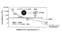
- the water jet discharged from the descaling nozzle becomes droplets, and the steel plate scale Attention was paid to cavitation occurring on the surface (see FIG. 4).
- FIG. 5 the phenomenon that the pressure generated when the bubbles generated by this cavitation disappear is significantly larger than the impact force generated when the droplet collides depending on the conditions.
- the present inventors thought that the descaling ability can be improved if cavitation can be positively imparted to the water jet. Therefore, as a result of conducting tests and diligent studies in various descaling systems (indicated by reference numeral 101 in FIG.
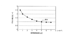
- the present inventors changed the dissolved oxygen concentration contained in the jet water by setting the descaling capability when normal jet water (raw water, dissolved oxygen concentration 5 ⁇ 10 ⁇ 3 g / l) was jetted to 1.
- the change of descaling ability when jetting water was injected was evaluated.
- the evaluation results are shown in FIG.
- the descaling capability is When the raw water was jetted, the descaling ability was 1, and it changed from about 0.9 times to about 2.5 times.
- the present inventors installed a deaeration device on the inlet side of the pump 170, and improved the descaling capability by lowering the dissolved oxygen concentration contained in the jet water than the dissolved oxygen concentration contained in the raw water. And invented a descaling system that can remove scale more efficiently.
- a descaling system is a descaling system installed in at least one position on the outlet side of a heating furnace, the inlet side of a roughing mill, and the inlet side of a finishing mill in a hot rolling line for steel sheets.
- a descaling nozzle for spraying water onto the surface of the steel sheet and thereby removing scale formed on the surface comprising a water supply source
- a descaling system that is connected to a pump that pressurizes water from the water and injects water pressurized by the pump onto the surface of the steel sheet, and is dissolved oxygen in water that is fed into the pump on the inlet side of the pump
- a deaeration device is provided that lowers the concentration below the dissolved oxygen concentration in the raw water from the water supply source.
- the degassing device converts the dissolved oxygen concentration in the water fed into the pump into the raw water from the water supply source. It is characterized by reducing the dissolved oxygen concentration to 1 ⁇ 10 -3 g / l or less greater than 0 g / l.
- the descaling system according to the present invention is the descaling system according to (1) or (2), wherein the degassing device reduces the dissolved oxygen concentration in the water fed to the pump by a vacuum degassing method. It is characterized by letting.
- the descaling system according to the present invention is the descaling system according to (1) or (2), wherein the degassing device lowers the dissolved oxygen concentration in the water fed to the pump by a heating degassing method. It is characterized by letting.
- the degassing device reduces the dissolved oxygen concentration in the water fed to the pump by a nitrogen purge method. It is characterized by letting.
- the degassing device is provided on the inlet side of the pump to lower the dissolved oxygen concentration in the water fed into the pump to be lower than the dissolved oxygen concentration in the raw water from the water supply source. .
- the dissolved oxygen concentration in the injection water injected toward the surface of a steel plate from a descaling nozzle can be reduced, descaling capability can be improved, and a scale can be removed more efficiently.
- the deaeration device converts the dissolved oxygen concentration in the water fed into the pump into the raw water from the water supply source.
- the dissolved oxygen concentration is reduced to greater than 0 g / l and less than or equal to 1 ⁇ 10 ⁇ 3 g / l.
- the dissolved oxygen concentration be larger than 0 g / l.
- the dissolved oxygen concentration is preferably 1 ⁇ 10 ⁇ 3 g / l or less. .
- the degassing device includes a vacuum degassing method, a heating degassing method, a nitrogen purge, respectively. It is possible to reduce the dissolved oxygen concentration in the water fed into the pump in this manner.
- FIG. 1 is a schematic configuration diagram showing an example of a descaling system according to the present invention together with a hot rolling line.
- FIG. 2 is an explanatory view showing a collision model of water droplets on a steel plate in scale removal by spray water.
- FIG. 3 is a schematic configuration diagram showing a conventional descaling system together with a hot rolling line.
- FIG. 4 is a schematic diagram showing an image of a state in which cavitation occurs when the water jet discharged from the descaling nozzle becomes droplets and collides with the steel plate scale surface.
- FIG. 5 is a diagram showing an image of a state in which pressure is generated when bubbles generated by cavitation shown in FIG.
- FIG. 6 shows a case in which a normal water (raw water, a dissolved oxygen concentration of 5 ⁇ 10 ⁇ 3 g / l) is sprayed with a descaling capability of 1 and a dissolved oxygen concentration contained in the water being changed. It is a graph which shows the result of having evaluated the change of the descaling capability when injecting.
- FIG. 1 is a schematic configuration diagram showing an example of a descaling system according to the present invention together with a hot rolling line.
- a descaling system 1 shown in FIG. 1 is provided in a hot rolling line for steel plates.
- the hot rolling line includes a heating furnace 10 that heats the material to be rolled (steel plate) K from the upstream side toward the downstream side, and a rough rolling machine 20 that roughly rolls the material K to be rolled out from the heating furnace 10. And a finish rolling mill 30 for finish rolling the roughly rolled material K.
- the descaling system 1 includes a first descaling device 40 called deskera installed on the outlet side (HSB) of the heating furnace 10 and the inlet side (RSB) of the rough rolling mill 20 in the hot rolling line for steel plates. ) And a third descaling device 60 installed on the entry side (FSB) of the finishing mill 30.
- the first descaling device 40 injects water onto the front and back surfaces of the material to be rolled K taken out from the heating furnace 10, and thereby a pair of descaling nozzles 41 for removing scales formed on the front and back surfaces. It has. Further, the second descaling device 50 injects water onto the front and back surfaces of the material to be rolled K that has passed through the first descaling device 40, thereby removing a pair of scales formed on the front and back surfaces. A scaling nozzle 51 is provided. Further, the third descaling device 60 injects water onto the front and back surfaces of the material to be rolled K that has passed through the roughing mill 20, and thereby a pair of descaling nozzles for removing scales formed on the front and back surfaces. 61 is provided.
- Each descaling nozzle 41, 51, 61 is connected to a plurality of pumps 70 and an accumulator 80 for pressurizing water from the water supply source 100 via pipes.
- Water from the water supply source 100 is pressurized by a plurality of pumps 70 and an accumulator 80 and stably kept at a high pressure from each descaling nozzle 41, 51, 61 toward the front and back surfaces of the material K to be rolled. Be injected.
- the discharged water discharge amount is stably secured by the plurality of pumps 70 and the accumulator 80.
- the dissolved oxygen concentration in the water fed into the plurality of pumps 70 is determined from the dissolved oxygen concentration in the raw water from the water supply source 100.
- a deaeration device 90 is also provided to reduce the temperature.
- the degassing device 90 a vacuum degassing method is used, but the dissolved oxygen concentration in the water fed to the plurality of pumps 70 may be reduced using a heat degassing method or a nitrogen purge method.
- a dissolved oxygen meter 91 is installed on the exit side of the deaerator 90.
- the deaeration device 90 for reducing the dissolved oxygen concentration in the water sent to the plurality of pumps 70 is provided on the inlet side of the plurality of pumps 70, the dissolution in the raw water sent from the water supply source 100 is provided.
- the oxygen concentration is lowered by the deaeration device 90, and the dissolved oxygen concentration in the water sent to the plurality of pumps 70 is lowered.
- the concentration of dissolved oxygen in the spray water that is sprayed from each pump 70 toward the front and back surfaces of the material to be rolled K from each descaling nozzle 41, 51, 61 and from each descaling nozzle 41, 51, 61 decreases Therefore, the descaling capability can be improved and the scale can be removed more efficiently.
- the dissolved oxygen concentration in the water sent to the plurality of pumps 70 is dissolved in the raw water from the water supply source 100.
- the oxygen concentration (usually about 5 ⁇ 10 ⁇ 3 g / l) is preferably decreased from 0 g / l to 1 ⁇ 10 ⁇ 3 g / l or less. Reducing the dissolved oxygen concentration to the 1 ⁇ 10 -3 g / l, 2 times descaling capacity for descaling ability of state of not completely degassed (usually about 5 ⁇ 10 -3 g / l) It becomes.
- the dissolved oxygen concentration in the spray water injected from the descaling nozzles 41, 51, 61 toward the front and back surfaces of the material K to be rolled is reduced to a suitable range. And the descaling ability can be greatly improved, and the scale can be removed more efficiently. Since it is technically difficult to make the dissolved oxygen concentration 0 g / l, it is preferable that the dissolved oxygen concentration be larger than 0 g / l. On the other hand, when the dissolved oxygen concentration is higher than 1 ⁇ 10 ⁇ 3 g / l, the degree of improvement in descaling ability is reduced. Therefore, the dissolved oxygen concentration is preferably 1 ⁇ 10 ⁇ 3 g / l or less. .
- the dissolved oxygen concentration in the water sent to the plurality of pumps 70 is changed to the dissolved oxygen concentration in the state of the raw water from the water supply source 100.
- the dissolved oxygen concentration in the water sent to the plurality of pumps 70 is not necessarily limited to the dissolved oxygen concentration in the raw water from the water supply source 100 (usually 5 ⁇ 10 ⁇ 3 g / 1) to greater than 0 g / l to 1 ⁇ 10 ⁇ 3 g / l or less.
- the descaling device may be installed at at least one position on the exit side of the heating furnace 10, the entry side of the roughing mill 20, and the entry side of the finishing mill 30. , It is not necessarily required to be installed at all positions. Further, the number of pumps 70 is not necessarily plural, and may be one. Furthermore, the dissolved oxygen meter 91 may be installed not only on the outlet side of the degassing device 90 but also on the inlet side of the degassing device 90 in order to manage the dissolved oxygen concentration before degassing.
- the degassing device 90 is a membrane vacuum degassing device using a gas separation membrane, and a dissolved oxygen meter (DO meter) 91 is installed on the outlet side of the degassing device 90. Then, the concentration of dissolved oxygen in the raw water (5 ⁇ 10 ⁇ 3 g / l) was reduced to 1 ⁇ 10 ⁇ 3 g / l by the deaerator 90.
- the deaeration device 90 since the deaeration device 90 is not installed, water having a dissolved oxygen concentration (5 ⁇ 10 ⁇ 3 g / l) in the raw water state is sent to the plurality of pumps 70.
- the steel material as the material to be rolled K has a standard sheet width of 1.2 m, a standard sheet thickness of the heating furnace 10 on the outlet side (HSB) 220 mm, the roughing mill 20 on the inlet side (RSB) 220 to 70 mm, and the finishing mill 30 An inlet side (FSB) of 60 to 40 mm was used.
- FIG. 2 is a diagram illustrating a collision model of water droplets on a steel material in scale removal by jet water.
- the total impact force (F) and the unit impact force (S) can be expressed by the following equations.
- the degassing device 90 reduces the dissolved oxygen concentration (5 ⁇ 10 ⁇ 3 g / l) in the raw water state to 1 ⁇ 10 ⁇ 3 g / l, thereby reducing the descaling capability.
- the water quality was improved by a factor of 2
- the occurrence rate of quality defects due to descaling ability could be reduced to less than 10% in the inventive example compared to the comparative example.
Landscapes
- Engineering & Computer Science (AREA)
- Mechanical Engineering (AREA)
- Cleaning And De-Greasing Of Metallic Materials By Chemical Methods (AREA)
- Degasification And Air Bubble Elimination (AREA)
Priority Applications (3)
| Application Number | Priority Date | Filing Date | Title |
|---|---|---|---|
| CN201380013987.4A CN104169014B (zh) | 2012-03-12 | 2013-03-07 | 除氧化皮系统 |
| KR1020147026443A KR101624448B1 (ko) | 2012-03-12 | 2013-03-07 | 디스케일링 시스템 |
| IN1674KON2014 IN2014KN01674A (fr) | 2012-03-12 | 2013-03-07 |
Applications Claiming Priority (2)
| Application Number | Priority Date | Filing Date | Title |
|---|---|---|---|
| JP2012054632A JP5739367B2 (ja) | 2012-03-12 | 2012-03-12 | デスケーリングシステム |
| JP2012-054632 | 2012-03-12 |
Publications (1)
| Publication Number | Publication Date |
|---|---|
| WO2013136734A1 true WO2013136734A1 (fr) | 2013-09-19 |
Family
ID=49160667
Family Applications (1)
| Application Number | Title | Priority Date | Filing Date |
|---|---|---|---|
| PCT/JP2013/001456 Ceased WO2013136734A1 (fr) | 2012-03-12 | 2013-03-07 | Système de détartrage |
Country Status (5)
| Country | Link |
|---|---|
| JP (1) | JP5739367B2 (fr) |
| KR (1) | KR101624448B1 (fr) |
| CN (1) | CN104169014B (fr) |
| IN (1) | IN2014KN01674A (fr) |
| WO (1) | WO2013136734A1 (fr) |
Cited By (1)
| Publication number | Priority date | Publication date | Assignee | Title |
|---|---|---|---|---|
| EP3601623B1 (fr) | 2017-03-22 | 2021-04-28 | Fives Stein | Procede et dispositif de refroidissement d'une bande d'acier en defilement dans une section de refroidissement d'une ligne continue |
Families Citing this family (1)
| Publication number | Priority date | Publication date | Assignee | Title |
|---|---|---|---|---|
| DE102023211482A1 (de) * | 2023-11-17 | 2025-05-22 | Sms Group Gmbh | Entzunderungssystem, Überwachungsvorrichtung und Überwachungsverfahren |
Citations (4)
| Publication number | Priority date | Publication date | Assignee | Title |
|---|---|---|---|---|
| JPH0673578A (ja) * | 1992-06-25 | 1994-03-15 | Yoshihide Shibano | ワークの表面処理方法 |
| JPH11189886A (ja) * | 1997-12-25 | 1999-07-13 | Babcock Hitachi Kk | 金属材料製造プロセスにおける表面処理装置及び表面処理方法 |
| JP2004238727A (ja) * | 2002-03-25 | 2004-08-26 | Jfe Steel Kk | 高炭素熱延鋼板およびその製造方法 |
| JP2007260550A (ja) * | 2006-03-28 | 2007-10-11 | Jfe Steel Kk | 複合ノズルおよび鋼材表面の処理方法 |
Family Cites Families (5)
| Publication number | Priority date | Publication date | Assignee | Title |
|---|---|---|---|---|
| JPH02182315A (ja) * | 1989-01-09 | 1990-07-17 | Sumitomo Metal Ind Ltd | 熱間圧延鋼板のスケール除去方法および装置 |
| JP3149583B2 (ja) * | 1992-11-25 | 2001-03-26 | 住友金属工業株式会社 | 脱スケール方法 |
| CN100411763C (zh) * | 2005-12-09 | 2008-08-20 | 广东韶钢松山股份有限公司 | 高压水除鳞系统 |
| KR200436513Y1 (ko) * | 2006-10-31 | 2007-08-31 | 한국전력공사 | 일체형 용존산소 제거 장치 |
| CN101559439A (zh) * | 2009-05-26 | 2009-10-21 | 广州金关节能科技发展有限公司 | 多段除鳞节能控制方法及其控制装置 |
-
2012
- 2012-03-12 JP JP2012054632A patent/JP5739367B2/ja active Active
-
2013
- 2013-03-07 IN IN1674KON2014 patent/IN2014KN01674A/en unknown
- 2013-03-07 KR KR1020147026443A patent/KR101624448B1/ko active Active
- 2013-03-07 WO PCT/JP2013/001456 patent/WO2013136734A1/fr not_active Ceased
- 2013-03-07 CN CN201380013987.4A patent/CN104169014B/zh active Active
Patent Citations (4)
| Publication number | Priority date | Publication date | Assignee | Title |
|---|---|---|---|---|
| JPH0673578A (ja) * | 1992-06-25 | 1994-03-15 | Yoshihide Shibano | ワークの表面処理方法 |
| JPH11189886A (ja) * | 1997-12-25 | 1999-07-13 | Babcock Hitachi Kk | 金属材料製造プロセスにおける表面処理装置及び表面処理方法 |
| JP2004238727A (ja) * | 2002-03-25 | 2004-08-26 | Jfe Steel Kk | 高炭素熱延鋼板およびその製造方法 |
| JP2007260550A (ja) * | 2006-03-28 | 2007-10-11 | Jfe Steel Kk | 複合ノズルおよび鋼材表面の処理方法 |
Cited By (2)
| Publication number | Priority date | Publication date | Assignee | Title |
|---|---|---|---|---|
| EP3601623B1 (fr) | 2017-03-22 | 2021-04-28 | Fives Stein | Procede et dispositif de refroidissement d'une bande d'acier en defilement dans une section de refroidissement d'une ligne continue |
| EP3601623B2 (fr) † | 2017-03-22 | 2025-03-26 | Fives Stein | Procédé et dispositif de refroidissement d'une bande d'acier en defilement dans une section de refroidissement d'une ligne continue |
Also Published As
| Publication number | Publication date |
|---|---|
| IN2014KN01674A (fr) | 2015-10-23 |
| JP5739367B2 (ja) | 2015-06-24 |
| CN104169014A (zh) | 2014-11-26 |
| CN104169014B (zh) | 2016-03-23 |
| JP2013188756A (ja) | 2013-09-26 |
| KR101624448B1 (ko) | 2016-05-25 |
| KR20140127349A (ko) | 2014-11-03 |
Similar Documents
| Publication | Publication Date | Title |
|---|---|---|
| KR101563206B1 (ko) | 후강판의 제조 설비 | |
| JP5834853B2 (ja) | 鋼板のスケール除去用ノズルおよび鋼板のスケール除去装置並びに鋼板のスケール除去方法 | |
| KR101490663B1 (ko) | 열연 강판용 냉각수 제거 장치 및 제거 방법 | |
| KR101691020B1 (ko) | 후강판의 제조 방법 및 제조 설비 | |
| JP3802830B2 (ja) | 鋼板のデスケーリング方法および設備 | |
| JP5739367B2 (ja) | デスケーリングシステム | |
| JP2014083578A (ja) | 熱間圧延鋼材のデスケ―リング用ノズル | |
| JP6350456B2 (ja) | 熱間圧延鋼材のデスケーリング方法およびデスケーリング装置、熱間圧延鋼材の製造方法および製造装置 | |
| JP3994582B2 (ja) | 鋼板のデスケーリング方法 | |
| JP6603159B2 (ja) | デスケーリング装置およびデスケーリング方法 | |
| JP2012035310A (ja) | 熱延鋼板の製造方法および製造設備 | |
| JP3811380B2 (ja) | 熱間圧延による厚鋼板の製造方法 | |
| JP3882465B2 (ja) | 表面性状の良好な熱延鋼板の製造方法 | |
| JP6787096B2 (ja) | 熱間圧延方法 | |
| JP6058976B2 (ja) | 鋼板のデスケーリング水温の管理方法 | |
| JP2900765B2 (ja) | 鋼材のデスケール方法 | |
| JP4677056B2 (ja) | 熱延鋼板の製造方法 | |
| JP5987816B2 (ja) | 熱間圧延のデスケーリング設備、デスケーリング方法および熱延鋼板の製造方法 | |
| JP5686061B2 (ja) | ローラレベラーによる厚鋼板の矯正方法 | |
| JPH06154837A (ja) | 脱スケール方法 | |
| JP2002316206A (ja) | 表面性状の優れた形鋼と該形鋼用の鋼材およびそれらの製造方法と製造装置 | |
| JP6518948B2 (ja) | 鋼板の製造方法および製造設備 | |
| JP2017144442A (ja) | 鋼材のデスケーリング方法及びデスケーリング装置 | |
| JP2006181612A (ja) | 表面性状に優れた酸洗鋼板の製造方法 | |
| JP2018051596A (ja) | 鋼板の製造方法および製造設備 |
Legal Events
| Date | Code | Title | Description |
|---|---|---|---|
| WWE | Wipo information: entry into national phase |
Ref document number: 201380013987.4 Country of ref document: CN |
|
| 121 | Ep: the epo has been informed by wipo that ep was designated in this application |
Ref document number: 13760964 Country of ref document: EP Kind code of ref document: A1 |
|
| NENP | Non-entry into the national phase |
Ref country code: DE |
|
| ENP | Entry into the national phase |
Ref document number: 20147026443 Country of ref document: KR Kind code of ref document: A |
|
| 122 | Ep: pct application non-entry in european phase |
Ref document number: 13760964 Country of ref document: EP Kind code of ref document: A1 |