WO2013136774A1 - Dispositif détecteur de signaux et procédé de détection de signaux - Google Patents
Dispositif détecteur de signaux et procédé de détection de signaux Download PDFInfo
- Publication number
- WO2013136774A1 WO2013136774A1 PCT/JP2013/001609 JP2013001609W WO2013136774A1 WO 2013136774 A1 WO2013136774 A1 WO 2013136774A1 JP 2013001609 W JP2013001609 W JP 2013001609W WO 2013136774 A1 WO2013136774 A1 WO 2013136774A1
- Authority
- WO
- WIPO (PCT)
- Prior art keywords
- signal
- detection
- power
- threshold
- received signal
- Prior art date
- Legal status (The legal status is an assumption and is not a legal conclusion. Google has not performed a legal analysis and makes no representation as to the accuracy of the status listed.)
- Ceased
Links
Images




Classifications
-
- H—ELECTRICITY
- H04—ELECTRIC COMMUNICATION TECHNIQUE
- H04L—TRANSMISSION OF DIGITAL INFORMATION, e.g. TELEGRAPHIC COMMUNICATION
- H04L7/00—Arrangements for synchronising receiver with transmitter
- H04L7/04—Speed or phase control by synchronisation signals
- H04L7/041—Speed or phase control by synchronisation signals using special codes as synchronising signal
- H04L7/042—Detectors therefor, e.g. correlators, state machines
-
- H—ELECTRICITY
- H04—ELECTRIC COMMUNICATION TECHNIQUE
- H04L—TRANSMISSION OF DIGITAL INFORMATION, e.g. TELEGRAPHIC COMMUNICATION
- H04L1/00—Arrangements for detecting or preventing errors in the information received
- H04L1/20—Arrangements for detecting or preventing errors in the information received using signal quality detector
- H04L1/201—Frame classification, e.g. bad, good or erased
-
- H—ELECTRICITY
- H04—ELECTRIC COMMUNICATION TECHNIQUE
- H04B—TRANSMISSION
- H04B7/00—Radio transmission systems, i.e. using radiation field
- H04B7/02—Diversity systems; Multi-antenna system, i.e. transmission or reception using multiple antennas
- H04B7/04—Diversity systems; Multi-antenna system, i.e. transmission or reception using multiple antennas using two or more spaced independent antennas
- H04B7/06—Diversity systems; Multi-antenna system, i.e. transmission or reception using multiple antennas using two or more spaced independent antennas at the transmitting station
- H04B7/0613—Diversity systems; Multi-antenna system, i.e. transmission or reception using multiple antennas using two or more spaced independent antennas at the transmitting station using simultaneous transmission
- H04B7/0615—Diversity systems; Multi-antenna system, i.e. transmission or reception using multiple antennas using two or more spaced independent antennas at the transmitting station using simultaneous transmission of weighted versions of same signal
- H04B7/0617—Diversity systems; Multi-antenna system, i.e. transmission or reception using multiple antennas using two or more spaced independent antennas at the transmitting station using simultaneous transmission of weighted versions of same signal for beam forming
-
- Y—GENERAL TAGGING OF NEW TECHNOLOGICAL DEVELOPMENTS; GENERAL TAGGING OF CROSS-SECTIONAL TECHNOLOGIES SPANNING OVER SEVERAL SECTIONS OF THE IPC; TECHNICAL SUBJECTS COVERED BY FORMER USPC CROSS-REFERENCE ART COLLECTIONS [XRACs] AND DIGESTS
- Y02—TECHNOLOGIES OR APPLICATIONS FOR MITIGATION OR ADAPTATION AGAINST CLIMATE CHANGE
- Y02D—CLIMATE CHANGE MITIGATION TECHNOLOGIES IN INFORMATION AND COMMUNICATION TECHNOLOGIES [ICT], I.E. INFORMATION AND COMMUNICATION TECHNOLOGIES AIMING AT THE REDUCTION OF THEIR OWN ENERGY USE
- Y02D30/00—Reducing energy consumption in communication networks
- Y02D30/70—Reducing energy consumption in communication networks in wireless communication networks
Definitions
- the present invention relates to a signal detection apparatus and a signal detection method for detecting a signal of another system.
- Wireless communication standards have been formulated or studied in millimeter wave wireless communication using the 60 GHz band.
- Major wireless LAN (Local Area Network) / Wireless PAN (Personal Area Network) standards that do not require a license include, for example, WiGig (Wireless Gigabit Network), IEEE 802.15.3c, Wireless HD (High Definition), ECMA- There are 387.
- WiGig Wireless Gigabit Network
- IEEE 802.15.3c Wireless HD (High Definition)
- the IEEE 802.11ad standard is being developed.
- a plurality of radio systems for example, single carrier system, OFDM (Orthogonal Frequency Division Division Multiplexing) system
- OFDM Orthogonal Frequency Division Division Multiplexing
- the frequency channels that can be used in the 60 GHz band are limited to 3 to 4 channels, it is expected that a plurality of different systems will use the same frequency channel when millimeter-wave wireless communication becomes widespread. The As a result, interference occurs between the systems, and there is a concern that the communication performance in each system may deteriorate.
- Carrier sense is a method of detecting a signal by detecting power.
- the carrier sense the power of the received signal is measured, and when the measured power value exceeds a predetermined threshold value, it is recognized that the signal is detected.
- a feature of carrier sense is that signals can be detected regardless of the type.
- Patent Document 1 As a carrier sense, for example, a technique disclosed in Patent Document 1 is known.
- Patent Document 1 for example, in the carrier sense of IEEE 802.11 CCA (Clear Channel ⁇ Assessment), if the power (level) exceeds a predetermined threshold, it is determined that the transmission medium is busy. Even if the predetermined threshold value is not exceeded, a method has been proposed in which a transition is made to a pending state in which it is determined whether or not the transmission medium is in use, and a busy state is detected when a preamble is detected in the pending state. Thereby, the signal of the electric power which does not exceed a predetermined threshold value can also be detected.
- Patent Document 1 can detect a weak power signal, but if noise exceeding a predetermined threshold is detected, the noise cannot be distinguished from the signal, and the noise is erroneously detected as a signal. In order to detect, there exists a problem that the sensitivity of electric power detection itself is not improved.
- the predetermined threshold is set low to improve the detection sensitivity, noise is likely to be erroneously detected as a signal.
- the predetermined threshold is set high to prevent erroneous detection, the detection sensitivity deteriorates. The problem has not been improved.
- An object of the present invention is to provide a signal detection device and a signal detection method that reduce false detection of detecting noise as a signal and improve power detection sensitivity.
- the signal detection apparatus of the present invention includes a power detection means for detecting a reception signal having a reception power exceeding a predetermined first threshold, a detected first reception signal, and a second detected next to the first reception signal.
- Correlation value calculating means for calculating a correlation value with a received signal
- absolute value calculating means for calculating an absolute value of the calculated correlation value
- determining means for determining the presence / absence of the detection target signal based on the threshold determination.
- the signal detection method of the present invention includes a power detection step of detecting reception power exceeding a predetermined first threshold, a first reception signal of the detected reception power, and reception power detected next to the first reception signal.
- a correlation value calculating step of calculating a correlation value with the second received signal, an absolute value calculating step of calculating an absolute value of the calculated correlation value, and a predetermined second value of the calculated absolute value of the correlation value And a determination step of determining presence / absence of a detection target signal based on threshold determination with a threshold.
- erroneous detection of detecting noise as a signal can be reduced, and power detection sensitivity can be improved.
- FIG. 5 is a diagram for explaining an autocorrelation detector disclosed in Patent Document 2. Diagram for explaining general autocorrelation method The block diagram which shows the structure of the signal detection apparatus which concerns on one embodiment of this invention The figure which uses for description of signal detection operation
- a transmission device for example, an access point
- the signal detection device is mounted on a receiving device (for example, a terminal device) that communicates with any of the communication systems in the plurality of communication systems described above, and the communication that the mounted receiving device communicates with.
- a receiving device for example, a terminal device
- a frame from a system hereinafter referred to as “own system”.
- the signal detection apparatus detects a plurality of frames of another system.
- the detection target frame may include a frame of the own system.
- FIG. 1 is a diagram showing a configuration of a signal detection device 100 according to Embodiment 1 of the present invention. Hereinafter, the configuration of the signal detection apparatus 100 will be described with reference to FIG.
- the signal detection device 100 includes a power detection unit 101, a storage unit 102, a multiplier 103, an integrator 104, an absolute value calculation unit 105, and a determination unit 106.
- the signal detection apparatus 100 inputs a reception signal obtained after radio reception processing (for example, down-conversion, analog-digital conversion) is performed on a radio reception signal received via an antenna in the reception apparatus, that is, a baseband signal. To do.
- the input received signal is distributed (duplicated), and a plurality of distributed signals are input to the power detection unit 101, the storage unit 102, and the multiplier 103.
- the power detection unit 101 detects the power of the input received signal, and outputs a trigger to the storage unit 102 when power exceeding the power detection threshold is detected.
- the storage unit 102 When the trigger is output from the power detection unit 101, the storage unit 102 stores the input reception signal as the first reception signal. Further, when the next trigger is output from the power detection unit 101, the storage unit 102 outputs the stored first reception signal to the multiplier 103, and stores the newly input reception signal as the second reception signal. To do.
- the multiplier 103 multiplies the input second received signal by the first received signal output from the storage unit 102 and outputs the multiplication result to the integrator 104.
- the integrator 104 integrates the multiplication result output from the multiplier 103 in a predetermined period, and outputs the integration result (that is, the correlation value between the second reception signal and the first reception signal) to the absolute value calculation unit 105. .
- the multiplier 103 and the integrator 104 function as correlation value calculation means.
- the absolute value calculation unit 105 calculates the absolute value of the correlation value output from the integrator 104 and outputs it to the determination unit 106.
- the determination unit 106 determines the presence or absence of a detection target signal based on the absolute value of the correlation value output from the absolute value calculation unit 105. Specifically, the determination unit 106 determines that the detection target signal is detected when the absolute value of the correlation value is equal to or greater than the signal detection threshold, and detects the detection target signal when the absolute value of the correlation value is less than the signal detection threshold. In other words, the first received signal and / or the second received signal is determined as noise.
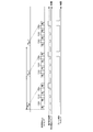
- FIG. 2 shows the received signal input timing, power detection timing, and detection target signal detection timing.
- the storage unit 102 stores the first reception signal S1.
- the storage unit 102 outputs the stored first received signal S1 to the multiplier 103.
- the second received signal S2 is stored. At this time, it is unknown whether the second reception signal S2 is a detection target signal or noise.
- the second received signal S2 input to the signal detection device 100 and the first received signal S1 output from the storage unit 102 are multiplied by the multiplier 103, and the multiplication result of the multiplier 103 is integrated by the integrator 104, A correlation value between the second received signal S2 and the first received signal S1 is obtained.
- the absolute value calculation unit 105 calculates the absolute value of the correlation value obtained by the integrator 104, and the determination unit 106 determines that the second reception signal S2 is the detection target signal if the correlation value is equal to or greater than the signal detection threshold. Is determined. Further, when the correlation value is less than the signal detection threshold, the determination unit 106 determines that the first reception signal S1 and / or the second reception signal S2 is noise.
- the power detection unit 101 when the second reception signal S2 exceeding the power detection threshold is noise, the correlation value between the first reception signal S1 and the second reception signal S2 becomes small, and the determination unit 106 Therefore, the frequency of erroneous detection of noise as a signal can be reduced. For this reason, the power detection sensitivity can be improved by setting the power detection threshold value of the power detection unit 101 low.
- the signal detection apparatus 100 sets the power detection threshold value low in order to improve the power detection sensitivity, and eliminates false detection of noise that tends to occur by detection detection processing using autocorrelation. As a result, it is possible to achieve both reduction in false detection of noise and improvement in power detection sensitivity.
- an operation for avoiding interference is started according to the power detected by the reception device including the signal detection device 100 or the frequency of detection.
- General operations for avoiding interference include, for example, frequency channel change, transmission timing change, transmission power control, and antenna directivity control.
- the correlation value with the previously detected reception signal is calculated, and the calculated correlation value is compared with the signal detection threshold.
- beacon frame for example, including time information of a wireless system
- a beacon frame group composed of several beacon frames is periodically transmitted. For this reason, it is difficult for the signal detection apparatus 100 to receive a plurality of beacon frames to which beamforming is applied with constant power.
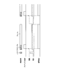
- FIG. 3 shows the input timing of the received signal, the power detection timing, and the frame detection timing.
- the signal detection apparatus 100 receives a beacon group including four beacons to which beamforming is applied.
- the first to third beacon groups are received.
- the received power of the first to fourth beacons included in the first beacon group received by the signal detection device 100 is different.
- the power is greater than or equal to the power detection threshold value, so the power detection unit 101 determines that there is a received signal, and the power is detected for the fourth beacon Since it is less than the threshold, the power detection unit 101 determines that there is no received signal.
- the presence or absence of a received signal is determined for the second beacon group for the fifth to eighth beacons, and the third beacon group for the ninth to twelfth beacons.
- the signal detection apparatus 100 uses the multiplier 103, the integrator 104, and the absolute value calculation unit 105 to correlate the first beacon and the second beacon, and the determination unit 106 detects the frame.
- the signal detection apparatus 100 performs a correlation calculation between the second beacon and the third beacon to detect a frame. Furthermore, the signal detection apparatus 100 performs a correlation calculation between the third beacon and the fifth beacon beyond the beacon group to detect a frame. Thereafter, the same operation as described above is performed.
- the determination unit 106 can detect a frame because the input correlation value is equal to or greater than the signal detection threshold.
- FIG. 4 shows received signal input timing, power detection timing, and frame detection timing.
- the fourth beacon, the eighth beacon, and the twelfth beacon exceed the power detection threshold. For this reason, it is difficult for the signal detection device 100 to take a correlation within each beacon group.
- the signal detection apparatus 100 performs a correlation operation between the fourth beacon of the first beacon group and the eighth beacon of the second beacon group, and detects a frame.
- the detection target signal is a beacon frame in which the same signal is repeatedly transmitted, even if the beacon frame has a different power detection level due to the application of beamforming, the first embodiment.
- the frame can be detected with high accuracy.
- frequency channels that can be used in the 60 GHz band are assumed to be 3 to 4 channels, when millimeter-wave wireless communication becomes widespread, different systems may use the same frequency channel. . For this reason, there is a concern that interference between systems occurs and the communication performance in each system is degraded.
- Patent Document 2 JP-A-2004-221940
- Non-Patent Document 1 IEEE Std 802.11-2007
- a signal pattern of a periodic signal used for the preamble portion is defined.
- a method of detecting the preamble by cross-correlation between a known signal pattern included in the preamble and the received signal is used.
- the method based on cross-correlation is not necessarily suitable.
- the period of the signal pattern used is common among several wireless communication standards, and the number of variations of the period of the periodic signal used for the preamble portion is relatively small compared to the number of variations of the signal pattern. Therefore, instead of the cross-correlation method, by providing an autocorrelation detector for the main period in the receiving apparatus, the receiving apparatus can widely detect interference signals from a wide variety of different systems.
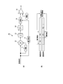
- FIG. 5 is a diagram for explaining the autocorrelation detector disclosed in Patent Document 2.
- FIG. 5A is a diagram showing a configuration of the autocorrelation detector 10 in Patent Document 2.
- FIG. 5B is a diagram conceptually showing processing in the autocorrelation detector.
- the first period portion of the periodic signal is represented by P1
- the second period portion is represented by P2.
- the autocorrelation detector performs a correlation operation between the first signal that is the received signal and the second signal obtained by delaying the first signal by the delay unit 11.
- the P1 portion and P2 portion of the first signal, and the P1 portion and P2 portion of the second signal are objects of correlation calculation processing.
- the second signal is given a delay of one period of the periodic signal, when calculating the correlation between the first signal and the second signal, the P2 part of the first signal is actually The correlation with the P1 portion of the two signals is calculated.
- the first signal and the delayed second signal are multiplied by the multiplier 12, and the multiplication result obtained by the multiplier 12 is integrated by the integrator 13 over a predetermined period. Is done. Thereby, a correlation value is obtained.
- the correlation calculation processing target is the P1 portion and P2 portion of the first signal and the P1 portion and P2 portion of the second signal
- the observation period of the power used for normalization also corresponds to both P1 and P2. It becomes. That is, the correlation value is normalized by the normalization unit 15 based on the average value of the power during the power observation period by the power detection unit 17, and the presence or absence of a signal is determined by the comparator 16 based on the normalized correlation value.
- Non-Patent Document 2 a general virtual carrier sense method disclosed in Non-Patent Document 2 is used.
- the virtual carrier sense method for example, in order to detect the signal of the own system in a wireless LAN, the frame length information is inserted into the frame header of the signal and transmitted, and the receiver extracts the frame length information from the signal. Determine the frame duration. Even if the reliability of carrier sense based on power is insufficient, the duration of a frame can be detected with high reliability by preamble detection and virtual carrier sense.
- CSMA carrier sense multiple access
- Non-Patent Document 2 it is necessary for the receiver to demodulate the received signal and decode the frame length information.
- frame length information in order to obtain frame length information from signals of a wide variety of different systems, it is necessary to demodulate the signals of all target different systems and decode the data. Applying the carrier sense method is not realistic.
- the purpose of the third embodiment is to provide a signal detection apparatus and a signal detection method for detecting a frame duration without demodulating a general signal including signals of various different systems.
- carrier sense the power of the received signal is measured, and if the measured power value exceeds a predetermined threshold, it is recognized that the signal has been detected.
- Carrier sense has a feature that a signal can be detected regardless of the type of system. On the other hand, depending on the power, there is a case where noise and a signal cannot be distinguished.
- carrier sense has the following relationship. If the predetermined threshold is set low to improve the detection sensitivity, erroneous detection that erroneously detects noise as a signal is likely to occur. Conversely, if the predetermined threshold is set high to prevent erroneous detection, Sensitivity deteriorates. In other words, there is a trade-off between improving detection sensitivity and preventing false detection.
- One is a cross-correlation method for detecting a detection target signal based on a correlation value between a preamble portion included in a received signal and a known pattern signal candidate used for the preamble portion.
- the other is an autocorrelation method for detecting a detection target signal based on a correlation value between preamble portions of a first signal and a second signal obtained by copying a received signal.
- a periodic signal in which a specific signal pattern is repeated is often used.
- the periodicity of the periodic signal is used for signal detection.
- the signal detection sensitivity of the autocorrelation method is lower than that of cross-correlation detection, but higher than that of carrier sense.
- the signal detection sensitivity of the autocorrelation method is higher than that of carrier sense because noise and a signal can be distinguished by the periodicity of the periodic signal.
- the autocorrelation method does not require the receiving side to know the specific signal pattern described above. Therefore, the receiving apparatus can be realized with a simple configuration. Further, in the autocorrelation method, it is only necessary to detect the periodicity of the waveform, so that it is not necessary to perform reception signal processing in accordance with the symbol rate of the interference signal.
- the autocorrelation method has an advantage that it can be easily applied to signal detection in different systems having different symbol rates or modulation methods.
- FIG. 6 is a diagram for explaining a general autocorrelation method.
- FIG. 6A shows the basic configuration of the autocorrelation detector 20
- FIG. 6B is a diagram conceptually showing the autocorrelation process.
- the second signal is delayed by the delay device 21 for a predetermined time out of the first signal and the second signal to which the received signal is distributed.
- the predetermined time corresponds to the period of the periodic signal used for the preamble portion of the detection target signal.
- the first signal and the delayed second signal are multiplied by the multiplier 22.
- a simple multiplier is provided, but a complex multiplier may be used. This is because a complex baseband signal is treated as a received signal and multiplied by a complex conjugate.
- the multiplication result obtained in the multiplier 22 is integrated over a predetermined period in the integrator 23 to obtain a correlation value.
- the absolute value of the obtained correlation value is calculated by the absolute value calculation unit 24, the absolute value of the calculated correlation value is compared with a predetermined threshold value, and a signal corresponding to the comparison result is output.
- the correlation value obtained from the complex baseband signal is a complex number.
- the obtained correlation value is a positive real number.
- the obtained correlation value may not necessarily be a positive real number.
- the correlation value obtained in the integrator 23 is not directly used for determination, but the absolute value of the correlation value is used for determination.
- the correlation component substantially matches the real number component, and the imaginary number component is caused by noise, for example.
- a real component of the correlation value may be used for the determination.
- the absolute value of the correlation value or the real component of the correlation value is input to the comparator 25 and compared with a predetermined threshold value. When the input value is larger than the predetermined threshold value, it is determined that the signal is detected by the comparator. Is done.
- an autocorrelation detector in order to minimize detection errors as much as possible and detect weak signals with high sensitivity, it is necessary to appropriately set a threshold value. Note that erroneous detection means that noise is not detected as a detection target signal, but an original detection target signal.
- a transmission device for example, an access point
- the signal detection apparatus according to Embodiment 3 of the present invention is mounted on a receiving apparatus that communicates in any one of the plurality of communication systems described above, for example, a terminal apparatus.
- the signal detection device detects a preamble signal from a plurality of communication systems (hereinafter referred to as “other systems”) other than the communication system (hereinafter referred to as “own system”) with which the mounted receiving device communicates. To do. In the following description, it is assumed that the signal detection device detects a plurality of preamble signals from other systems, but the preamble signal to be detected may be included in the preamble signal to be detected.
- FIG. 7 is a block diagram showing the configuration of the signal detection apparatus 50 according to Embodiment 3 of the present invention.
- the signal detection device 50 receives a reception signal (that is, a baseband signal) obtained after a radio reception signal received via an antenna in the reception device is subjected to radio reception processing (for example, down-conversion, analog-digital conversion). As input.
- a reception signal that is, a baseband signal
- radio reception processing for example, down-conversion, analog-digital conversion
- the preamble detection unit 51 detects the preamble at the beginning of the frame and outputs a preamble detection signal to the threshold control unit 53 and the determination unit 55.
- the use of the autocorrelation detector shown in FIG. 6 as the preamble detection unit 51 is suitable for signal detection in a heterogeneous system, but is not limited to this, and other preamble detection units (for example, cross-correlation detectors) May be used.
- the average power calculation unit 52 calculates the average power of the input signal for the most recent predetermined time, and outputs the calculated average power to the threshold control unit 53.
- the average time is set to a time sufficient to smooth a short time fluctuation. As the average time is increased, for example, malfunction due to instantaneous fluctuations in noise can be reduced, and precise threshold setting is possible. However, the delay in detection timing increases because the response to changes in the signal is delayed, and the delay is too large. And CSMA operation will be hindered. It is preferable to set it to several to several tens of times the reciprocal of the bandwidth of the input signal.
- the average power calculation operation may obtain an accurate average value over a predetermined time, but may be a smoothing operation using a low-pass filter, for example.
- the threshold controller 53 sets a threshold based on the average power output from the average power calculator 52. Specifically, before the preamble detection signal is input, the threshold value control unit 53 sets a value obtained by adding a predetermined level margin (first level margin value) to the average power as the first threshold value. Prevent detection. This is an operation that emphasizes the reduction of false detection. Note that the first threshold may be infinite and the detection operation may be substantially invalidated.
- the threshold value control unit 53 receives a preamble detection signal, and when the average power of the input preamble detection signal is lower than the first threshold value, the threshold value control unit 53 has a predetermined level margin (first power) with respect to the average power (preamble unit power). A value obtained by subtracting (2 level margin value) is set as the second threshold value. This is an operation that places importance on detection sensitivity. In addition, by using two threshold values, it is possible to achieve both improvement in detection sensitivity and reduction in false detection.
- the threshold control unit 53 when notified from the power detection unit 54 that the signal power is below the second threshold over a predetermined determination time, the threshold control unit 53 returns to the first threshold before the preamble detection signal is input.
- the method of returning from the second threshold value to the first threshold value may be instantaneously changed or may be gradually changed stepwise or smoothly over a predetermined time. By gradually changing the threshold value, it is possible to prevent frame detection from being ended erroneously due to instantaneous fluctuations in the signal, and stable frame detection can be performed.
- the threshold control unit 53 includes a timer that counts a predetermined timeout time. When the signal power does not fall from the preamble detection timing over the timeout time, the first threshold value before the preamble detection signal is input is restored. Thereby, for example, it is possible to prevent the false detection from continuing for a long time due to the fluctuation of the background noise level.
- the timeout time is preferably set to the maximum frame length that is normally used for the signal to be detected.
- the power detection unit 54 compares the power of the input signal with a threshold controlled by the threshold control unit 53, and outputs a power detection signal to the determination unit 55 when the power is greater than the threshold. In addition, when the power of the input signal falls below the second threshold over a predetermined determination time, the power detection unit 54 notifies the threshold control unit 53 to that effect.
- the fact that the signal power falls below the second threshold for a predetermined determination time means that the frame duration has ended, so that the frame duration can be detected.
- the determination unit 55 outputs a logical sum of the preamble detection signal output from the preamble detection unit 51 and the power detection signal output from the power detection unit 54 as a detection determination signal. That is, if either one or both of the preamble and the power is detected, it is determined that the signal is detected. This operation is effective in the following cases.
- the threshold control unit 53 needs time from detection of the preamble to calculation of an appropriate threshold. This is because time is required for the average operation or calculation for accurately measuring the power of the preamble portion. Therefore, the rise of the power detection signal is delayed from the preamble detection timing. This delay time is not negligible. For example, when the CSMA operation is disturbed, a signal is generated by the preamble detection signal regardless of the power detection signal in which a delay occurs by using the logical sum of the power detection signal and the preamble detection signal. Detection can be determined.
- the determination unit 55 may include a timeout process similar to the timeout time of the threshold control unit 53. That is, the determination unit 55 may forcibly invalidate the detection determination signal after a predetermined time has elapsed from the preamble detection timing.
- the determination unit 55 may forcibly invalidate the detection determination signal before preamble detection, after the falling edge of the power detection signal, and after the timeout time elapses. This is an operation equivalent to setting the first level margin to infinity in the threshold control unit 53.
- a first threshold value obtained by adding the first level margin value to the average power is set. For this reason, even if noise occurs, since the power of the noise is less than the first threshold value, signal detection is not performed and erroneous detection can be prevented.
- the second threshold obtained by subtracting the second level margin value from the average power (preamble portion power) is set. Sensitivity can be improved.
- the first threshold value obtained by adding the first level margin value to the average power of the input signal is set, and after the preamble detection, the average power is lower than the first threshold value.
- the second threshold value obtained by subtracting the second level margin value from the average power is set, and determining that the duration of the frame has ended when the signal power falls below the second threshold value for a predetermined determination time.
- the description has been made on the assumption that a preamble detection unit for detecting the preamble at the beginning of the frame is provided.
- the preamble detection unit instead of the preamble detection unit, other characteristic signals existing near the beginning of the frame are detected. It is good also as a feature signal detection part.
- the feature signal for example, a unique word for frame capture, a synchronization signal, or a frame header can be used.
- Preamble detecting means for detecting a preamble portion arranged at the head of the frame of the received signal; Power detection means for detecting the power of the received signal exceeding a variable threshold; Threshold control means for controlling the variable threshold based on detection of the preamble portion; Comprising The power detection means determines that the duration of the frame has ended when the power of the received signal falls below a predetermined determination time with respect to the variable threshold set when the preamble portion is detected.
- the preamble unit is a periodic signal.
- the threshold control means sets the variable threshold to the first threshold before the preamble portion is detected, and detects the preamble portion, and the average power of the received signal is lower than the first threshold
- the signal detection device according to claim 1, wherein the variable threshold is set to a second threshold.
- the threshold control means sets the variable threshold to the second threshold, and when the average power of the received signal falls below the second threshold for a predetermined determination time, the first threshold before detecting the preamble portion.
- the threshold control unit gradually changes from the second threshold to the first threshold.
- each functional block used in the description of each of the above embodiments is typically realized as an LSI which is an integrated circuit. These may be individually made into one chip, or may be made into one chip so as to include a part or all of each functional block.
- the name used here is LSI, but it may also be called IC, system LSI, super LSI, or ultra LSI depending on the degree of integration.
- the method of circuit integration is not limited to LSI, and may be realized by a dedicated circuit or a general-purpose processor.
- An FPGA Field Programmable Gate Array
- An FPGA Field Programmable Gate Array
- a reconfigurable processor in which connection and setting of circuit cells in the LSI can be reconfigured may be used.
- the signal detection device and the signal detection method according to the present invention can be applied to a reception device that communicates with any one of a plurality of communication systems, for example, a terminal device.
Landscapes
- Engineering & Computer Science (AREA)
- Computer Networks & Wireless Communication (AREA)
- Signal Processing (AREA)
- Quality & Reliability (AREA)
- Mobile Radio Communication Systems (AREA)
Abstract
L'invention concerne un dispositif détecteur de signaux et un procédé de détection de signaux qui permettent de réduire les erreurs de détection faisant prendre le bruit pour un signal, et d'améliorer la sensibilité de détection de puissance. Une unité détectrice de puissance (101) détecte la puissance d'un signal d'entrée reçu, et, si la puissance détectée dépasse un seuil de détection de puissance, elle émet un déclencheur à destination d'une unité de stockage (102). Si elle reçoit le déclencheur à son entrée, ladite unité de stockage (102) stocke un premier signal reçu, mais si elle reçoit un déclencheur consécutif à son entrée, elle émet le premier signal stocké à destination d'un multiplicateur (103), et elle stocke un second signal reçu. Ledit multiplicateur (103) multiplie le second signal reçu par le premier signal reçu, un intégrateur (104) intègre les résultats de la multiplication qui sont émis par le multiplicateur (103) lors d'un laps de temps imposé, déduisant une valeur de corrélation du second signal reçu et du premier signal reçu, et une unité de calcul de valeur absolue (105) calcule la valeur absolue de la valeur de corrélation qui est émise par ledit intégrateur (104). Sur la base de la valeur absolue de la valeur de corrélation qui est émise par ladite unité de calcul de valeur absolue (105), une unité de détermination (106) détermine si un signal à détecter est présent.
Priority Applications (1)
| Application Number | Priority Date | Filing Date | Title |
|---|---|---|---|
| US14/114,168 US9270444B2 (en) | 2012-03-15 | 2013-03-12 | Signal detector device and signal detection method |
Applications Claiming Priority (4)
| Application Number | Priority Date | Filing Date | Title |
|---|---|---|---|
| JP2012-058608 | 2012-03-15 | ||
| JP2012058608A JP5793098B2 (ja) | 2012-03-15 | 2012-03-15 | 信号検出装置及び信号検出方法 |
| JP2012-067343 | 2012-03-23 | ||
| JP2012067343A JP5852486B2 (ja) | 2012-03-23 | 2012-03-23 | 信号検出装置及び信号検出方法 |
Publications (1)
| Publication Number | Publication Date |
|---|---|
| WO2013136774A1 true WO2013136774A1 (fr) | 2013-09-19 |
Family
ID=49160703
Family Applications (1)
| Application Number | Title | Priority Date | Filing Date |
|---|---|---|---|
| PCT/JP2013/001609 Ceased WO2013136774A1 (fr) | 2012-03-15 | 2013-03-12 | Dispositif détecteur de signaux et procédé de détection de signaux |
Country Status (2)
| Country | Link |
|---|---|
| US (1) | US9270444B2 (fr) |
| WO (1) | WO2013136774A1 (fr) |
Cited By (2)
| Publication number | Priority date | Publication date | Assignee | Title |
|---|---|---|---|---|
| JP2016146518A (ja) * | 2015-02-06 | 2016-08-12 | 株式会社国際電気通信基礎技術研究所 | 無線通信装置およびチャネル占有状況検知方法 |
| JP2024001349A (ja) * | 2019-01-09 | 2024-01-09 | オシア インク. | 無線電力送信のためのタイミング取得モジュール |
Families Citing this family (2)
| Publication number | Priority date | Publication date | Assignee | Title |
|---|---|---|---|---|
| US10356719B2 (en) * | 2016-06-24 | 2019-07-16 | Microsoft Technology Licensing, Llc | Skip-correlation based symmetric carrier sensing with multiple power levels |
| TWI739349B (zh) | 2020-03-18 | 2021-09-11 | 瑞昱半導體股份有限公司 | 通訊裝置與動態調整封包偵測閥值的方法 |
Citations (3)
| Publication number | Priority date | Publication date | Assignee | Title |
|---|---|---|---|---|
| JP2005295085A (ja) * | 2004-03-31 | 2005-10-20 | Nec Corp | キャリア検出方法/プログラム/プログラム記録媒体/回路、受信機 |
| JP2009253911A (ja) * | 2008-04-10 | 2009-10-29 | Toshiba Corp | 信号検出装置、無線通信装置および方法 |
| WO2010056888A1 (fr) * | 2008-11-12 | 2010-05-20 | Qualcomm Incorporated | Procédé et appareil permettant d'évaluer un canal libre directionnel dans un système de communication sans fil |
Family Cites Families (4)
| Publication number | Priority date | Publication date | Assignee | Title |
|---|---|---|---|---|
| JP4254245B2 (ja) | 2003-01-15 | 2009-04-15 | ソニー株式会社 | 通信装置 |
| JP5106291B2 (ja) * | 2008-07-24 | 2012-12-26 | 株式会社東芝 | 通信装置 |
| JP2010130118A (ja) | 2008-11-25 | 2010-06-10 | Sony Corp | 送信装置、受信装置、通信システム、および、受信装置における処理方法 |
| EP2541980A4 (fr) | 2010-02-24 | 2013-11-27 | Kyocera Corp | Dispositif de terminal mobile, station de base et procédé d'évitement de brouillage |
-
2013
- 2013-03-12 US US14/114,168 patent/US9270444B2/en not_active Expired - Fee Related
- 2013-03-12 WO PCT/JP2013/001609 patent/WO2013136774A1/fr not_active Ceased
Patent Citations (3)
| Publication number | Priority date | Publication date | Assignee | Title |
|---|---|---|---|---|
| JP2005295085A (ja) * | 2004-03-31 | 2005-10-20 | Nec Corp | キャリア検出方法/プログラム/プログラム記録媒体/回路、受信機 |
| JP2009253911A (ja) * | 2008-04-10 | 2009-10-29 | Toshiba Corp | 信号検出装置、無線通信装置および方法 |
| WO2010056888A1 (fr) * | 2008-11-12 | 2010-05-20 | Qualcomm Incorporated | Procédé et appareil permettant d'évaluer un canal libre directionnel dans un système de communication sans fil |
Cited By (2)
| Publication number | Priority date | Publication date | Assignee | Title |
|---|---|---|---|---|
| JP2016146518A (ja) * | 2015-02-06 | 2016-08-12 | 株式会社国際電気通信基礎技術研究所 | 無線通信装置およびチャネル占有状況検知方法 |
| JP2024001349A (ja) * | 2019-01-09 | 2024-01-09 | オシア インク. | 無線電力送信のためのタイミング取得モジュール |
Also Published As
| Publication number | Publication date |
|---|---|
| US20140056394A1 (en) | 2014-02-27 |
| US9270444B2 (en) | 2016-02-23 |
Similar Documents
| Publication | Publication Date | Title |
|---|---|---|
| US11933874B2 (en) | Electronic device for performing ranging by using ultra-wideband in wireless communication system, and method of operating the electronic device | |
| KR101055364B1 (ko) | 매체 상에서의 코-채널 전송들을 선택적으로 무시하는 방법및 장치 | |
| JP2006222665A (ja) | 無線通信用送受信装置における制御装置及び無線通信用送受信方法 | |
| CN106412931B (zh) | 一种基于多时隙融合机制的lte-u空闲信道评估方法 | |
| CN117203914A (zh) | 信号处理方法、装置、设备及存储介质 | |
| JP5667497B2 (ja) | 信号検出装置及び信号検出方法 | |
| CN116781104A (zh) | 基于超带宽的信息反馈方法及装置 | |
| WO2013136774A1 (fr) | Dispositif détecteur de signaux et procédé de détection de signaux | |
| EP3596852B1 (fr) | Détection de signal basée sur une résonance stochastique | |
| Baradkar et al. | Implementation of energy detection method for spectrum sensing in cognitive radio based embedded wireless sensor network node | |
| US8022858B2 (en) | Radar detection method and apparatus using the same | |
| Thangalakshmi et al. | Matched filter detection based spectrum sensing in cognitive radio networks | |
| KR20210013999A (ko) | 레이더 신호 검출 방법 | |
| Nair et al. | A fast two stage detector for spectrum sensing in cognitive radios | |
| JP5852486B2 (ja) | 信号検出装置及び信号検出方法 | |
| JP5793098B2 (ja) | 信号検出装置及び信号検出方法 | |
| WO2017016331A1 (fr) | Procédé et appareil de détection de signal radar | |
| Zhang et al. | A practical ranging method using IR-UWB signals | |
| CN112165364A (zh) | 窄带频谱感知系统的增强频谱感知方法 | |
| Armi et al. | Sensing time-based throughput performance in OFDM cognitive radio system | |
| Armi et al. | Performance of energy detector with certain and uncertain noise in OFDM cognitive radio system | |
| Hao et al. | A particle filter and joint likelihood ratio based error source diagnosing method for IEEE 802.11 networks | |
| Schmidt et al. | Indoor positioning via WLAN channel state information and machine learning classification approaches | |
| Sood et al. | Capacity optimization using cognitive radios networks | |
| Sasaki et al. | High-Precision 5G-NR Downlink Signal Detection Sensor Developed Using Software-Defined Radio |
Legal Events
| Date | Code | Title | Description |
|---|---|---|---|
| WWE | Wipo information: entry into national phase |
Ref document number: 14114168 Country of ref document: US |
|
| 121 | Ep: the epo has been informed by wipo that ep was designated in this application |
Ref document number: 13761682 Country of ref document: EP Kind code of ref document: A1 |
|
| NENP | Non-entry into the national phase |
Ref country code: DE |
|
| 122 | Ep: pct application non-entry in european phase |
Ref document number: 13761682 Country of ref document: EP Kind code of ref document: A1 |