WO2013136974A1 - Procédé de purification de particules modifiées et leur procédé de fabrication, particules modifiées, matériau fonctionnel, élément optique, élément de transfert thermique, dispositif d'analyse du taux de couverture et procédé associé - Google Patents
Procédé de purification de particules modifiées et leur procédé de fabrication, particules modifiées, matériau fonctionnel, élément optique, élément de transfert thermique, dispositif d'analyse du taux de couverture et procédé associé Download PDFInfo
- Publication number
- WO2013136974A1 WO2013136974A1 PCT/JP2013/055000 JP2013055000W WO2013136974A1 WO 2013136974 A1 WO2013136974 A1 WO 2013136974A1 JP 2013055000 W JP2013055000 W JP 2013055000W WO 2013136974 A1 WO2013136974 A1 WO 2013136974A1
- Authority
- WO
- WIPO (PCT)
- Prior art keywords
- sample
- modified
- fine particles
- modifier
- surface area
- Prior art date
- Legal status (The legal status is an assumption and is not a legal conclusion. Google has not performed a legal analysis and makes no representation as to the accuracy of the status listed.)
- Ceased
Links
Images



Classifications
-
- B—PERFORMING OPERATIONS; TRANSPORTING
- B01—PHYSICAL OR CHEMICAL PROCESSES OR APPARATUS IN GENERAL
- B01D—SEPARATION
- B01D15/00—Separating processes involving the treatment of liquids with solid sorbents; Apparatus therefor
- B01D15/08—Selective adsorption, e.g. chromatography
- B01D15/26—Selective adsorption, e.g. chromatography characterised by the separation mechanism
- B01D15/40—Selective adsorption, e.g. chromatography characterised by the separation mechanism using supercritical fluid as mobile phase or eluent
-
- B—PERFORMING OPERATIONS; TRANSPORTING
- B01—PHYSICAL OR CHEMICAL PROCESSES OR APPARATUS IN GENERAL
- B01D—SEPARATION
- B01D11/00—Solvent extraction
- B01D11/02—Solvent extraction of solids
- B01D11/0203—Solvent extraction of solids with a supercritical fluid
-
- B—PERFORMING OPERATIONS; TRANSPORTING
- B01—PHYSICAL OR CHEMICAL PROCESSES OR APPARATUS IN GENERAL
- B01D—SEPARATION
- B01D11/00—Solvent extraction
- B01D11/02—Solvent extraction of solids
- B01D11/0215—Solid material in other stationary receptacles
- B01D11/0223—Moving bed of solid material
-
- B—PERFORMING OPERATIONS; TRANSPORTING
- B01—PHYSICAL OR CHEMICAL PROCESSES OR APPARATUS IN GENERAL
- B01D—SEPARATION
- B01D15/00—Separating processes involving the treatment of liquids with solid sorbents; Apparatus therefor
- B01D15/02—Separating processes involving the treatment of liquids with solid sorbents; Apparatus therefor with moving adsorbents
-
- B—PERFORMING OPERATIONS; TRANSPORTING
- B05—SPRAYING OR ATOMISING IN GENERAL; APPLYING FLUENT MATERIALS TO SURFACES, IN GENERAL
- B05D—PROCESSES FOR APPLYING FLUENT MATERIALS TO SURFACES, IN GENERAL
- B05D1/00—Processes for applying liquids or other fluent materials
- B05D1/18—Processes for applying liquids or other fluent materials performed by dipping
- B05D1/185—Processes for applying liquids or other fluent materials performed by dipping applying monomolecular layers
-
- B—PERFORMING OPERATIONS; TRANSPORTING
- B05—SPRAYING OR ATOMISING IN GENERAL; APPLYING FLUENT MATERIALS TO SURFACES, IN GENERAL
- B05D—PROCESSES FOR APPLYING FLUENT MATERIALS TO SURFACES, IN GENERAL
- B05D7/00—Processes, other than flocking, specially adapted for applying liquids or other fluent materials to particular surfaces or for applying particular liquids or other fluent materials
- B05D7/24—Processes, other than flocking, specially adapted for applying liquids or other fluent materials to particular surfaces or for applying particular liquids or other fluent materials for applying particular liquids or other fluent materials
-
- C—CHEMISTRY; METALLURGY
- C08—ORGANIC MACROMOLECULAR COMPOUNDS; THEIR PREPARATION OR CHEMICAL WORKING-UP; COMPOSITIONS BASED THEREON
- C08K—Use of inorganic or non-macromolecular organic substances as compounding ingredients
- C08K9/00—Use of pretreated ingredients
- C08K9/04—Ingredients treated with organic substances
- C08K9/06—Ingredients treated with organic substances with silicon-containing compounds
-
- G—PHYSICS
- G01—MEASURING; TESTING
- G01N—INVESTIGATING OR ANALYSING MATERIALS BY DETERMINING THEIR CHEMICAL OR PHYSICAL PROPERTIES
- G01N5/00—Analysing materials by weighing, e.g. weighing small particles separated from a gas or liquid
- G01N5/04—Analysing materials by weighing, e.g. weighing small particles separated from a gas or liquid by removing a component, e.g. by evaporation, and weighing the remainder
-
- B—PERFORMING OPERATIONS; TRANSPORTING
- B82—NANOTECHNOLOGY
- B82Y—SPECIFIC USES OR APPLICATIONS OF NANOSTRUCTURES; MEASUREMENT OR ANALYSIS OF NANOSTRUCTURES; MANUFACTURE OR TREATMENT OF NANOSTRUCTURES
- B82Y30/00—Nanotechnology for materials or surface science, e.g. nanocomposites
-
- B—PERFORMING OPERATIONS; TRANSPORTING
- B82—NANOTECHNOLOGY
- B82Y—SPECIFIC USES OR APPLICATIONS OF NANOSTRUCTURES; MEASUREMENT OR ANALYSIS OF NANOSTRUCTURES; MANUFACTURE OR TREATMENT OF NANOSTRUCTURES
- B82Y40/00—Manufacture or treatment of nanostructures
-
- G—PHYSICS
- G01—MEASURING; TESTING
- G01N—INVESTIGATING OR ANALYSING MATERIALS BY DETERMINING THEIR CHEMICAL OR PHYSICAL PROPERTIES
- G01N15/00—Investigating characteristics of particles; Investigating permeability, pore-volume or surface-area of porous materials
- G01N15/08—Investigating permeability, pore-volume, or surface area of porous materials
- G01N2015/0833—Pore surface area
-
- Y—GENERAL TAGGING OF NEW TECHNOLOGICAL DEVELOPMENTS; GENERAL TAGGING OF CROSS-SECTIONAL TECHNOLOGIES SPANNING OVER SEVERAL SECTIONS OF THE IPC; TECHNICAL SUBJECTS COVERED BY FORMER USPC CROSS-REFERENCE ART COLLECTIONS [XRACs] AND DIGESTS
- Y10—TECHNICAL SUBJECTS COVERED BY FORMER USPC
- Y10T—TECHNICAL SUBJECTS COVERED BY FORMER US CLASSIFICATION
- Y10T428/00—Stock material or miscellaneous articles
- Y10T428/29—Coated or structually defined flake, particle, cell, strand, strand portion, rod, filament, macroscopic fiber or mass thereof
- Y10T428/2982—Particulate matter [e.g., sphere, flake, etc.]
- Y10T428/2991—Coated
Definitions
- the present invention relates to a modified fine particle with very few impurity components, a functional material containing such a modified fine particle, an optical member, a heat transfer member, and a method for purifying and producing a modified fine particle capable of obtaining such a modified fine particle. It is about.
- the present invention also relates to a coverage analysis apparatus and a coverage analysis method for analyzing the coverage with a modifier on the surface of fine particles modified with the modifier.
- nano-particles have been promoted in various fields (see, for example, Patent Documents 1 to 7 and Non-Patent Documents 1 to 3).
- Patent Documents 1 to 4 various methods for surface modification of nanoparticles by binding and fixing a modifier on the surface of the nanoparticles have been studied in order to impart various functions to the nanoparticles (for example, Patent Documents 1 to 4). 7, Non-Patent Documents 1 to 3).
- the nanoparticles are likely to aggregate because they are fine particles, and therefore the original function of the nanoparticles is often not expressed. Therefore, surface modification of nanoparticles is used as one of the techniques for suppressing aggregation and stably isolating nanoparticles.
- the nanoparticles tend to aggregate, and the aggregated nanoparticles remain substantially aggregated during the modification reaction for binding and fixing the modifier on the surface of the nanoparticles. For this reason, the aggregated nanoparticles have voids between the nanoparticles, and impurities are taken into the voids after the modification reaction.
- the modified nanoparticles whose surface is modified by bonding and fixing the modifier to the surface thereof are produced in a state containing a large amount of impurities such as unreacted modifier, by-product and solvent.
- Patent Documents 1 to 7 and Non-Patent Documents 1 to 3 use a supercritical solvent in the reaction field.
- the solvent and the modifier enter between the nanoparticles that are aggregated as giant aggregated particles. For this reason, aggregation of nanoparticles during the modification reaction can be suppressed by setting the reaction field to a supercritical state.
- separation of the produced nanoparticles from the reaction mixture can be performed by applying a method known in the art, and in general, water and organic such as hydrophilic or hydrophobic are used. It is disclosed that phase separation or phase distribution can be performed using a solvent, and solvent extraction, chromatography, or the like can be preferably used.
- Patent Document 2 after the reaction, particles are collected from the reactor using water and methanol, and centrifuged at 10100 rpm for 20 minutes to obtain a precipitate. Then, ethanol is added to the precipitate, followed by centrifugation. It is disclosed that the unreacted reagent attached to the precipitate is removed by performing the applying operation twice under the same conditions as described above.
- the aggregated nanoparticles have voids between the nanoparticles, and after the modification reaction, impurities are taken into the voids. Moreover, even if aggregation during the modification reaction can be suppressed, impurities are incorporated during reaggregation by reaggregating after the modification reaction.
- the same peak is observed in the IR spectrum regardless of whether the modifying agent is bonded and fixed to the surface of the nanoparticle or is not bonded and only taken between the nanoparticles.
- Patent Document 3 discloses that, regarding the collection of organic modified fine particles as a product, the product was collected by repeating water washing and chloroform washing twice.
- Patent Document 3 discloses that, regarding the fine particles after the modification reaction, a peak that appears to be derived from the modifying agent is seen in the IR spectrum. However, for the reasons described above, even in Patent Document 3, the question that a large amount of unreacted modifier that has not been removed remains unwieldy.
- Patent Document 4 a surface modifier is reacted and added in the presence of an organic solvent to the surface of nano hollow particles made of silica shell, and then the surface-modified disperse silica nano hollow particles are stirred with a high-speed stirrer. It is disclosed that after dispersion, ultrasonic dispersion is performed in the presence of a modified silicone oil and filtered through a sieve having a mesh of 25 ⁇ m to obtain a high-concentration dispersion.
- Patent Document 4 discloses that an organic solvent and a surface modifier are added to nano hollow particles made of silica shells and stirred with a high-speed stirrer to disperse giant aggregated particles aggregated to a particle size of about 5 ⁇ m in the organic solvent. Then, it is filtered through a sieve and strongly dispersed with a wet jet mill to form fine agglomerated particles with a particle size of about 0.5 ⁇ m or less, and evaporator-concentrated and heat-dried to achieve surface-modified dispersibility A method for obtaining silica nano hollow particles is disclosed.
- the nanoparticles are in an agglomerated state, and no particular mention is made regarding the removal of unreacted modifiers and by-products.
- Patent Documents 5 and 6 do not mention any method for removing unreacted modifiers and by-products after the modification reaction.
- Patent Document 5 IR charts of fine inorganic particles before and after the modification reaction are posted.
- Patent Document 5 removes unreacted modifiers and by-products after the modification reaction. The question of unreacted modifier remaining in large quantities cannot be wiped out.
- Non-Patent Documents 1 to 3 describe that the product is extracted with a solvent, filtered and dried. However, in this case as well, the question that a large amount of unreacted modifier remains for the reasons described above cannot be wiped out.
- Patent Document 7 as a method for recovering the generated ultrafine particles as monodisperse fine particles, a coolant in which a surfactant is dissolved is injected into the supercritical solution, and the supercritical solution is rapidly cooled from the outside.
- a surfactant is adsorbed on the surface of the ultrafine particles, and the generated ultrafine particles are recovered as monodispersed fine particles.
- Patent Document 7 does not mention any method for removing the used surfactant.
- Patent Documents 1 to 7 and Non-Patent Documents 1 to 3 have no description and data on the purity of the product.
- the nanoparticles are only separated from the reaction mixture by using a general separation method such as filtration or centrifugation.
- a general separation method such as filtration or centrifugation.
- the removal of the unreacted modifier and by-products which are dispersed is merely removed, and the unreacted modifier and by-products incorporated in the aggregated nanoparticles are not removed.
- the present invention has been made in view of the above problems, and the first object thereof is a modified fine particle having an extremely small amount of impurity components and a function having high performance exceeding conventional performance, including such a modified fine particle. It is an object of the present invention to provide a refining material, an optical member, a heat transfer member, and a method for purifying and producing modified fine particles capable of obtaining such modified fine particles.
- a sample made of fine particles is also simply expressed as a sample.
- a specific surface area analysis method such as a BET adsorption method (hereinafter also simply referred to as a BET method) is widely used.
- the BET method is a method in which an inert gas (for example, N 2 gas) is adsorbed on the surface of cooled fine particles, and the specific surface area per unit volume is measured from the amount of the inert gas.
- N 2 gas for example, N 2 gas
- the coverage of the fine particles can be calculated as a ratio between the specific surface area of the fine particles not modified with the modifier and the specific surface area of the fine particles modified with the modifier. Details regarding the BET method are described in Non-Patent Document 4, for example.
- the measurement accuracy may decrease. This decrease in the measurement accuracy of the coverage is due to a decrease in the measurement accuracy of the specific surface area of the fine particles modified with the modifier.
- FIG. 12A is a schematic diagram showing the surface of fine particles that are not modified by a modifying material.
- FIG. 12B is a schematic diagram showing the surface of fine particles modified with a slight amount of modifying material.
- (C) of FIG. 12 is a schematic diagram showing the surface of fine particles modified with a relatively large number of modifiers.
- N 2 molecules when not modified by a modifying material, N 2 molecules are uniformly adsorbed on the surface of the fine particles.
- N 2 molecules when the surface is modified with a slight amount of modifier, N 2 molecules are uniformly present on the surface of the fine particles except for the region modified with the modifier. Adsorb. Therefore, in these cases, the specific surface area of the sample can be accurately measured by the BET method.
- N 2 molecules are adsorbed on the surface of the fine particles in addition to the region modified with the modifier. There will be no areas. This is because the N 2 molecule is less likely to enter between the modified material, be a region N 2 molecules should adsorption would otherwise, because the region N 2 molecules are not adsorbed occurs.
- the specific surface area of the region modified with the modifier is calculated based on the adsorption amount of N 2, the region not actually modified with the modifier is also included in the region modified with the modifier. It will be. As a result, the accuracy of the coverage obtained based on the specific surface area of the region modified with the modifier is reduced.
- a second object of the present invention is to provide a coverage analysis apparatus and a coverage analysis method that can accurately measure the coverage of a sample surface with a modifier.
- the method for purifying modified fine particles binds to fine particles having a primary particle diameter of less than 100 nm, to which a surface modifier is bound and fixed, and to the surfaces of the fine particles.
- a solvent containing a compound that is not fixed is brought into contact with a trap material larger than the fine particles, and the compound that is contained in the solvent and is not bonded and fixed to the surface of the fine particles is trapped in the trap material. Trap with to remove.
- the method for producing modified fine particles comprises contacting a fine particle having a primary particle diameter of less than 100 nm with a surface modifier in a supercritical solvent.
- a modification reaction step for binding and fixing the surface modifier on the surface of the fine particles, a fine particle having a primary particle diameter of less than 100 nm to which the surface modifier is bonded and fixed, and a compound that is not bonded and fixed to the surface of the fine particles In a supercritical state, the containing solvent is brought into contact with a trap material larger than the fine particles, and the compounds contained in the solvent that are not bonded and fixed to the surface of the fine particles are trapped and removed by the trap material. Purification step.
- the modified fine particle according to one aspect of the present invention is a modified fine particle in which a surface modifier is bonded and fixed to the surface of a fine particle having a primary particle diameter of less than 100 nm, and is a pyrolytic type. Impurity component ratio measured by gas chromatography mass spectrometry is less than 30%.
- the coverage analysis apparatus has a coverage that represents a ratio of a region modified with the modifier on the surface of the sample modified with the modifier.
- the coverage analysis method provides a coverage representing a ratio of a region modified with a modifier on the surface of the sample modified with the modifier.
- the functional material containing the modified fine particles, and the optical member and the heat transfer member made of such a functional material are not adversely affected by the elution of impurity components, and contain more modified fine particles. Can be dispersed. Therefore, according to this invention, articles
- the mass of the modifying material that is modifying the sample surface is measured by thermogravimetric analysis, and the specific surface area of the surface of the sample that is not modified by the modifying material is measured by specific surface area analysis.
- FIG. 2 is a decomposition GC chart of the product obtained in Example 1.
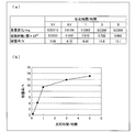
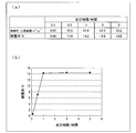
- FIG. 2 is a decomposition GC chart of the product obtained in Comparative Example 1. It is the schematic which shows the structure of the coverage analysis apparatus concerning one Embodiment of this invention. It is a figure which shows the flow of a process in the coverage analysis apparatus concerning one Embodiment of this invention. It is a figure which shows the flow of a process in the coverage analysis apparatus concerning one Embodiment of this invention. (A) is a figure which shows the coverage measured in the Example of this invention, (b) is the figure which plotted the said coverage with respect to the modification reaction time at the time of modifying a modifier.
- (A) is a figure which shows the coverage derived
- (b) is the figure which plotted the said coverage with respect to the modification reaction time at the time of modifying a modifier.
- (A) to (c) are schematic views showing a state in which an inert gas is adsorbed on the sample surface when the coverage is measured by specific surface area analysis in the conventional coverage analysis method.
- Embodiment 1 Hereinafter, Embodiment 1 of the present invention will be described in detail.
- the present embodiment relates to a method for producing modified fine particles (hereinafter referred to as “modified nanoparticles”) obtained by surface modification of fine particles having a particle size of nanometer size, referred to as nanoparticles, and at least a purification process.
- modified nanoparticles obtained by surface modification of fine particles having a particle size of nanometer size, referred to as nanoparticles, and at least a purification process.
- the present invention relates to a method of using a supercritical solvent (supercritical fluid) in an initial stage.
- the method for producing modified nanoparticles according to the present embodiment includes at least a modification reaction process and a purification process.
- the modified nanoparticle production method mainly includes (1) any of the modification reaction process and the purification process. (2) When using a supercritical fluid only for the modification reaction process, (3) When using a supercritical fluid for the modification reaction process and the purification process, (4) Only for the purification process When using a critical fluid, the following four methods are conceivable.
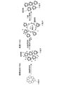
- FIG. 1 is a diagram schematically showing the state of nanoparticles when a supercritical fluid is used in (3) the modification reaction process and the purification process.
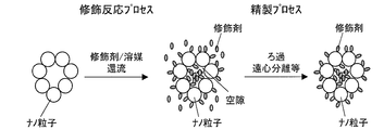
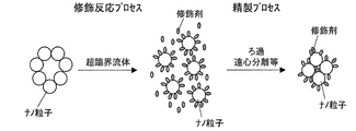
- FIGS. 2 and 3 respectively show (1) when the supercritical fluid is not used in any of the modification reaction process and the purification process, and (2) when the supercritical fluid is used only for the modification reaction process. It is a figure which shows the state of a nanoparticle typically.
- modifying agent a surface decorating agent (hereinafter simply referred to as “modifying agent”) and a solvent are added to the nanoparticles and refluxed. By doing so, the modifier is bound and fixed to the surface of the nanoparticles. Ultrasonic irradiation and ball milling may be performed, but it is known that they cannot be sufficiently dispersed to the primary particle level.
- the nanoparticles are usually agglomerated, and when the reaction is carried out in a normal solvent, the agglomeration is hardly dissolved and the agglomerated state of the nanoparticles is maintained. For this reason, in this case, impurities such as unreacted modifiers, by-products and solvents are taken into the voids of the aggregates of nanoparticles whose surfaces are modified.
- the modification reaction when the modification reaction is performed in a supercritical state, even if the nanoparticles are aggregated to form secondary particles or tertiary particles, the supercritical fluid and the modifying agent are secondary particles or tertiary particles. Penetration between the agglomerated nanoparticles forming the. As a result, each nanoparticle which is a primary particle reacts with the modifying agent, and the modifying agent is bonded and fixed to the surface of each nanoparticle, thereby forming a modified nanoparticle. As a result, the modified nanoparticles are dispersed as primary particles (or in a state close thereto), and impurities such as unreacted modifiers and by-products are present around them.
- the modified nanoparticles aggregated to form secondary particles or tertiary particles as shown in the middle diagram in the scheme of FIG.
- the supercritical solvent penetrates between the aggregated modified nanoparticles, and the aggregation of the modified nanoparticles can be solved. For this reason, impurities can be trapped in the dummy fine particles while the modified nanoparticles are dispersed as primary particles or a state close thereto.
- the nanoparticles easily aggregate, and when the reaction is carried out in a normal solvent as shown in FIG. 2, the aggregation is hardly solved in the process until the product is obtained. For this reason, the modifier cannot be efficiently bonded and fixed to the surface of the nanoparticles. In addition, since many modifiers that are not bonded and fixed to the nanoparticle surface are present in the solvent, many modifiers are wasted compared to the case where a supercritical fluid is used in the modification reaction process.
- the supercritical fluid and the modifier are aggregated even if the nanoparticles are aggregated to form secondary particles or tertiary particles. It penetrates between the nanoparticles and is bonded and fixed to the surface of each nanoparticle.
- the obtained modified nanoparticles are dispersed as primary particles or in a state close to the primary particles, and impurities such as unreacted modifiers and by-products are present around them.
- impurities such as unreacted modifier can be efficiently removed from the system.
- the coating ratio of the modifier on the nanoparticle surface is high, the dispersibility is improved, so that it is difficult to aggregate, and as a result, it becomes more difficult to incorporate impurities.
- the high dispersibility leads to an improvement in the filling rate when the modified nanoparticles are composited with a polymer or the like.
- the influence of surface energy on the characteristics becomes larger.
- the particle size of the fine particles decreases, the surface energy of the fine particles increases and the interaction with the polymer increases. For this reason, when the particle diameter of the fine particles becomes small, the dispersibility of the fine particles in the polymer tends to be lowered. In order to reduce the interaction, it is effective to reduce the area of the interface, that is, to increase the particle diameter.
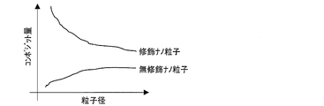
- FIG. 4 shows the particle diameters of the modified nanoparticles and unmodified nanoparticles when the surface-modified modified nanoparticles or unmodified nanoparticles are composited with PMMA (polymethyl methacrylate), and the composite amount to PMMA. It is a graph which shows the relationship.
- the composite amount of the modified nanoparticles to PMMA increased as the particle size of the modified nanoparticles decreased.
- the modified nanoparticles in a good monodispersed state can form a good composite material.
- a dispersant is used in combination to ensure dispersibility.
- the dispersant is used to improve the mixing property between the nanoparticles and a medium such as a polymer, but is generally used at least half the amount of the nanoparticles, and preferably used in an amount equivalent to the nanoparticles.
- TiO 2 titanium oxide
- TiO 2 titanium oxide
- organic surfactants that are essentially unrelated to increasing the refractive index can be plasticizers, resulting in a decrease in the glass transition point, a decrease in heat resistance, and so-called impurities.
- the modification reaction process is a step of bonding the modifier to the nanoparticle surface by bringing the nanoparticles and the modifier into contact with each other in a solvent, as described in the modification reaction process described in the scheme shown in FIG. 1 or FIG.
- various known modification reaction processes in which a modifier is bonded and fixed to the nanoparticle surface can be used.
- modification reaction when the modifier is bonded to the nanoparticle surface by bringing the nanoparticle and the modifier into contact in a supercritical fluid, the modification reaction itself is as follows: For example, modification reactions as shown in Patent Documents 1 to 6 and Non-Patent Documents 1 to 3 can be used.
- the purification process is a step of trapping and removing a compound that is not bonded and fixed to the nanoparticle surface in a supercritical fluid with a trap material.
- the compound that is not bonded and fixed to the nanoparticle surface is an impurity other than the target modified nanoparticle, and mainly a modifier and a by-product that are not bonded and fixed to the nanoparticle surface. Indicates.
- the step of trapping a compound that is not bonded and fixed to the nanoparticle surface with a trap material and the step of removing the compound that is not bonded and fixed to the surface of the nanoparticle from the system may be performed separately. It may be performed simultaneously.
- the purification process is performed by mixing a trap material with a solvent containing a modified nanoparticle and a free compound that is not bonded and fixed to the modified nanoparticle in a supercritical state.
- a step of trapping a compound which is not bonded and fixed to the substrate with a trap material and a step of removing the trap material from the system, specifically from the solvent.
- a solvent in a supercritical state containing a modified nanoparticle and a free compound that is not bonded and fixed to the modified nanoparticle is passed through a container containing a trap material, whereby the solvent It may include a step of trapping and removing the compound contained therein that is not bonded and fixed to the nanoparticle surface with the trap material.
- the purification process may comprise a step of drying the modified nanoparticles after removing the compound.
- Nanoparticles In the present embodiment, fine particles having a primary particle size of less than 100 nm are preferably used as the nanoparticles used as the raw material.
- the purification process according to the present embodiment is an important element in order to obtain modified nanoparticles with very few impurities.
- the particle diameter of the nanoparticles can be measured by a known measurement method such as a transmission electron microscope, an adsorption method, a light scattering method, an X-ray small angle scattering method, or an X-ray diffraction.
- a known measurement method such as a transmission electron microscope, an adsorption method, a light scattering method, an X-ray small angle scattering method, or an X-ray diffraction.
- the above nanoparticles are used as cores (core particles) of modified nanoparticles.
- the nanoparticles are not particularly limited as long as they are fine particles that do not dissolve in a solvent used as a supercritical fluid in a reaction field in a reaction system.
- the nanoparticles are typically inorganic fine particles, but may be organic fine particles made of an organic material such as a crosslinkable compound, and a composite mainly composed of either an organic material or an inorganic material. Fine particles may be used.
- nanoparticles examples include zinc oxide, aluminum oxide, silicon nitride, aluminum nitride, titanium oxide, titanate, zirconate titanate, niobate, tantalate, tungstate, gallium phosphate, and Rochelle. Examples thereof include salt, topaz, tourmaline, and silica.
- nanoparticles may be used alone or in appropriate combination of two or more.
- the modifier is not particularly limited as long as it can be bonded and fixed to the surface of the nanoparticle, and may be appropriately selected according to the type of nanoparticle and the function to be imparted to the nanoparticle. .
- the modifier for example, various known modifiers that can chemically bond an organic residue to the surface of the nanoparticles can be used.
- modifiers examples include isocyanate compounds, amine compounds, vinyl compounds, epoxy compounds, methacryloxy compounds, acrylic compounds, imide compounds, and the like in Patent Documents 1 to 6 and Non-Patent Documents 1 to 3.
- Known organic modifiers as shown can be used.
- the modifiers include, for example, silane couplings such as octadecyltrimethoxysilane, dimethoxydiphenylsilane, and aminopropyltrimethoxysilane.
- silane couplings such as octadecyltrimethoxysilane, dimethoxydiphenylsilane, and aminopropyltrimethoxysilane.
- a silane compound (organofunctional silane) such as an agent can be used alone or in combination with an organic modifier as described above. Such a compound is strongly chemically bonded to the surface of the inorganic or organic nanoparticles by a condensation reaction or the like.
- the organic functional group is firmly bonded to the surface of a nanoparticle made of silica fine particles, titanium oxide, aluminum oxide, or the like via, for example, a reactive silyl group or silanol group, and the modifier is difficult to peel off. Modified nanoparticles can be obtained.
- the solvent used in the method for producing modified nanoparticles according to this embodiment that is, the reaction field for the modification reaction according to this embodiment and the treatment field for the purification treatment are preferably supercritical fluids (super A critical solvent) is used.
- the supercritical fluid is a substance that has been placed at a temperature or pressure above the critical point, indicating that the substance is indistinguishable from gas and liquid.
- the solvent used in the present embodiment is not particularly limited, and includes aliphatic alcohols such as methanol, ethanol, and propanol, aliphatic hydrocarbons such as n-hexane and ketone, aromatic hydrocarbons such as xylene, and dioxide. Carbon, water, etc., for example, the solvents described in Patent Documents 1 to 7 and Non-Patent Documents 1 to 3 can be used.
- carbon dioxide, methanol, ethanol, acetone, and water are preferable because they are easy to handle in terms of temperature and pressure, and among them, various solvents are used.
- Carbon dioxide or methanol is preferably used because it has high solubility and can be handled at a relatively low temperature and low pressure.
- Methanol is suitable when the modifier is highly polar.
- the trap material is particularly limited as long as it is larger than the above-mentioned nanoparticles and can trap (capture) impurities, particularly unreacted modifiers, that are not bonded and fixed to the nanoparticle surface in the supercritical fluid. It is not something.
- the capture said here may be fixation by adsorption
- the trap material may be formed of the same material as the nanoparticles or may be formed of a different material.
- the trapping material used in the present embodiment may be, for example, a trapping dummy particle having a larger diameter than the nanoparticle to be used and made of the same material as the nanoparticle.
- the size of the trap material may be larger than the nanoparticles used as described above, but it is preferably a size of micron order or more.
- the material of the trap material is not particularly limited as long as it can trap impurities, particularly unreacted modifiers, that are not bonded and fixed to the nanoparticle surface in the supercritical fluid.
- the trap material examples include adsorbents having a hydrophilic surface.
- examples of such an adsorbent include polar adsorbents such as silica and alumina.
- Silica and alumina have a large specific surface area, excellent adsorption ability, heat resistance and water resistance, and adsorb many organic compounds that have functional groups that can be assumed to be used as modifiers. Therefore, it is suitable as a trap material.
- the trap material used in the present embodiment is not limited to this, the surface may be hydrophobic, and the surface may have both a hydrophilic group and a hydrophobic group. Good. Only one type of trap material may be used, or two or more types of trap materials may be used in combination as appropriate. That is, the trap material may be appropriately selected or used in combination depending on the type of the solvent and the modifier.
- an adsorbent with a hydrophobic surface such as activated carbon is suitable for adsorbing a weakly polar organic substance from a polar solvent.
- a hydrophobic surface such as activated carbon
- the treatment site is water-based, generally, particles having high hydrophobicity tend to aggregate, but the use of a supercritical fluid can suppress particle aggregation.
- a polar adsorbent such as silica or alumina whose surface is hydrophilic as a trapping material
- water and other polar molecules can be selectively adsorbed, while an adsorbent with a hydrophobic surface is non- Polar molecules can be selectively adsorbed.
- the trapping material when trapping dummy particles having a larger diameter than the nanoparticles to be used and made of the same material as the nanoparticles are used as the trapping material, the trapping material is brought into contact with the unreacted modifier in the supercritical fluid.
- the unreacted modifier can be bound and fixed to the surface of the trapping dummy particles.
- the trap material is made of a material having an affinity for the unreacted modifier, as in the case where the trap material is a dummy particle made of the same material as the nanoparticles used, the unreacted modifier can be efficiently used. It can be recovered by trapping.
- the nanoparticle when the nanoparticle is a fine particle having a hydrophilic surface such as silica, the fine particle itself has a hydrophilic property, but the hydrophilicity is reduced by the modification.
- the surface modification of the nanoparticles suppresses the adsorption of impurities to the modified nanoparticles.
- impurities can be efficiently adsorbed in such a state by mixing an unmodified trap material in the modified nanoparticles.
- the shape of the trap material is not particularly limited, and may be particulate, and may be a fiber, preferably a fiber bundle or cotton-like fiber such as glass wool.
- the trap material is formed in a fiber shape and the surface area is increased, impurities can be easily trapped in the fiber mesh.
- the trap material is easily removed from the reaction / purification system and has a sufficient surface area. For this reason, since the specific surface area is large as the trap material, an adsorbent having a porous structure is preferably used.
- Such a trap material is not particularly limited as long as the pore diameter on the trap material surface is smaller than that of the nanoparticles.
- the trap material can be easily separated and removed by filtering using a filter or sieve having a diameter larger than that of the nanoparticles and smaller than that of the trap material. Therefore, the trap material is not particularly limited as long as it is larger than the nanoparticles.
- the trap material has a size that can be easily removed by filtration or centrifugation, for example, a diameter of about several ⁇ m to several hundred ⁇ m. It is desirable that
- the trap material may be mixed directly into the solvent and taken out from the solvent after the trap treatment, or may be used in a container such as a column as a purification system separately from the reaction system.
- the trap is connected to the reaction vessel used for the modification reaction via a connecting member such as a valve that can open and close the connecting portion (connecting port) between the reaction vessel and the containing vessel containing the trap material.
- the container containing the material is connected, and after the modification reaction is completed, the connection part is opened to include the modified nanoparticles and impurities that are not bonded and fixed to the surface of the modified nanoparticles after the modification reaction.
- the solvent in the supercritical state may be passed through the storage container in the supercritical state without returning to normal temperature and normal pressure (that is, room temperature and atmospheric pressure).
- the compound contained in the solvent and not fixed to the nanoparticle surface can be trapped and removed by the trapping material.
- the purification process may further include a step of filtering the treatment liquid after removing glass wool or the treatment liquid after permeating through a container containing a trap material such as a silica column.
- the reaction field in the modification reaction process and the treatment field in the purification process can be obtained in an apparatus capable of achieving high-temperature and high-pressure conditions.
- Such an apparatus that is, an apparatus for bringing the field (specifically, a solvent used in each process) into a supercritical state is not particularly limited.
- a batch apparatus batch apparatus
- an autoclave pressure-resistant reactor or the like can be used.
- the reaction apparatus used for the modification reaction process and the treatment apparatus used for trapping impurities in the purification process may be different from each other. However, as a series of processes related to the production of modified nanoparticles, the purification process continues after the modification reaction. When performing the above, it is desirable to use the same apparatus from the viewpoint of preventing the yield from decreasing.
- the critical fluid be transferred to the purification process while containing the reactants and trap material.
- a container such as a column in which a trap material is accommodated (for example, packed) like a silica column or an alumina column is used as an impurity removing apparatus via a connecting member such as a valve. It may be connected.
- a filtration device such as a vacuum filtration device may be connected to the processing device as an impurity removal device via a connection member such as a valve.
- the trap material and impurities can be removed continuously after trapping the impurities by the trap material without taking out the processing liquid from the processing apparatus.
- the apparatus may be provided with a separate inlet for introducing the trap material into the apparatus after the modification reaction, and the addition apparatus for adding (input) the trap material into the apparatus is connected to a valve or the like, for example. It may be connected via a member.
- reaction temperature / reaction pressure in the modification reaction and the treatment temperature / treatment pressure in the trap treatment are such that the solvent can maintain a supercritical state at a temperature / pressure higher than the critical temperature / critical pressure of the solvent.
- What is necessary is just to set suitably according to the kind of said solvent, and if it is the temperature and pressure which the said solvent can maintain a supercritical state, it will not specifically limit.
- the conditions are 304K and 7.38 MPa or more
- the conditions are 512.6 K and 8.09 MPa or more.
- the modification reaction time may be appropriately set according to the type of nanoparticles and the modifying agent so that the desired modification reaction is completed, and the contact time with the trap material is also reduced by impurities such as unreacted modifying agent. What is necessary is just to set suitably according to the kind, usage-amount, etc. of a trap material, a modifier, and a solvent so that it can adsorb
- the ratio between the nanoparticles and the modifier may be appropriately set according to the type of nanoparticles used, the type of modifier, and the like so that the desired modified nanoparticles can be obtained, and is particularly limited. It is not a thing.
- the ratio between the nanoparticles and the modifying agent is that the modification reaction on the surface of the nanoparticles becomes an interfacial reaction, so it is necessary to use a large excess of the modifying agent with respect to the nanoparticles.
- the amount of modifier used is too large, the unreacted modifier removal process cannot be performed easily.
- the ratio of nanoparticles: modifier 1: several hundred to several tens of thousands is set. It is preferable to do.
- the amount of the supercritical fluid is not particularly limited as long as it is set to an amount that can sufficiently dissolve the modifier and can sufficiently immerse the nanoparticles.
- the trap material is not particularly limited as long as it is used in a large excess with respect to the nanoparticles so as to trap the added excessive excess modifier. It suffices that the total surface area of the added trapping material can secure a sufficient area for the amount of unreacted modifier to be adsorbed and fixed.
- the modified nanoparticles after removal of impurities by the trap material can be recovered as powdered modified nanoparticles by drying after removing the solvent by filtration or the like as necessary, as described above.
- the drying is preferably performed for a certain period of time under reduced pressure. Thereby, the modified nanoparticles can be efficiently dried.
- the decompression conditions are not particularly limited as long as the solvent can be completely removed.
- trapping impurities in the supercritical fluid with the trapping material allows the pyrolysis gas chromatography mass spectrometry (hereinafter, referred to as the primary particle diameter to be less than 100 nm).
- modified nanoparticles having a primary particle diameter of less than 100 nm and a purity calculated by GC-Mass analysis of 70% or more, preferably 80% or more, and more preferably 90% or more can be obtained.
- GC-Mass analysis of the modified nanoparticles confirmed that there was almost no impurity component and only the modifier layer bonded and fixed to the nanoparticle surface as the main peak.
- the modified nanoparticles can be used for various applications as a composite material by being composited with a base material such as a polymer.
- a typical strategy is to mix other high refractive index materials with the polymer.
- a composite polymer having a high performance that exceeds the conventional performance such as a solid or liquid composite, is produced as a functional material. can do.
- Such a functional material can be suitably used for an optical member or a heat conducting member, for example.
- the functional material is, for example, a high refractive index polymer
- the high refractive index polymer can be used, for example, as a material for various lenses.
- examples of the optical member include a lens widely used in glasses, a camera such as a portable camera or a digital camera, a CCD (Charge Coupled Device), and an optical disk pickup.
- a camera such as a portable camera or a digital camera
- CCD Charge Coupled Device
- the focal length can be shortened compared to the case where a conventional lens material is used. Can be rounded).
- a conventional glass such as glasses is replaced with an optical member using such a functional material, there is an advantage that the weight can be extremely reduced.
- examples of the optical member include a light diffusing material such as a diffusing film used in a liquid crystal panel, and an antireflection film.
- the functional material is, for example, a high thermal conductive polymer
- the high thermal conductive polymer may be used as a material for a printed board, a heat sink, an LED board or molding material, a heat exchange pipe or panel of an air conditioner, or the like. it can.
- thermal design is becoming very important as the size is reduced year by year. That is, a mechanism design that efficiently eliminates heat generated by an element such as a CPU (central processing unit) is very important for the performance of each element.
- Such a heat transfer member can be improved relatively easily if a metal material can be used, but since most of the members have an adverse effect if the insulation is not high, it is often the case that a metal material cannot be used. is there.
- a highly thermally conductive polymer is highly demanded as a material for such a heat transfer member.
- weight reduction can also be achieved by using a polymer as a material of such a heat transfer member.
- nanoparticles for aiming at a high refractive index include titanium oxide, barium titanate, and zinc oxide.
- nanoparticles for aiming at high thermal conductivity include aluminum oxide, silicon nitride, and aluminum nitride.
- nanoparticles composed of barium titanate, lead zirconate titanate, etc. are suitable.
- barium titanate, other titanates, titanate Zirconate (lead, etc.), niobate (potassium, lithium, etc.), tantalate (potassium, lithium, etc.), tungstate (natrim, etc.), zinc oxide, aluminum nitride, gallium phosphate, Rochelle salt, topaz Nanoparticles composed of tourmaline, etc. are suitable.
- examples of polymers suitable for use as a base material for imparting flexibility include polyethylene, polypropylene, polyvinyl alcohol, polyamide-based polymers, polyethylene terephthalate, and polyoxymethylene.
- examples of polymers suitable for use as a base material for imparting rigidity include aromatic polyamides, aromatic polyesters, polyazomethines, and heterocyclic polymers.
- aromatic polyamide, aromatic polyether, aromatic polysulfide, polyimide, polyarylate, polyetherketone, polyethersulfone, etc. are suitable, and shape memory properties are imparted.
- polynorbornene, trans-polyisoprene, styrene-butadiene block copolymer, polyurethane, and the like are preferable.
- polymethyl methacrylate, polystyrene, polycarbonate, and the like are preferable. .
- the functional material containing the modified nanoparticles and various articles such as an optical member and a heat transfer member made of the functional material may be liquid or solid.
- the base material for compositing the modified nanoparticles is not limited to a polymer, and various liquid or solid materials capable of compositing the modified nanoparticles can be used.
- modified nanoparticles or the functional material containing the modified nanoparticles can be suitably used for various other applications as described in, for example, Patent Documents 1 to 7 and Comparative Patent Documents 1 to 3.
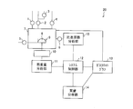
- FIG. 7 is a schematic diagram showing the configuration of the coverage analysis apparatus 20.
- the coverage analysis apparatus 20 is an apparatus that analyzes the coverage representing the ratio of the region modified with the modifying material on the surface of the sample modified with the modifying material.
- the sample to be analyzed in the coverage analysis apparatus 20 is a substance whose surface is modified with a modifying material, and particularly a fine powder or fine particle sample can be suitably analyzed.
- the fine particle sample (sample made of fine particles) is also simply referred to as a sample.
- the surface of the fine particles is also expressed as the surface of the sample. Examples of samples that can be analyzed by the coverage analyzer 20 include the silica fine particles described in the first embodiment.
- the fine particles to be analyzed in the coverage analyzer 20 have a known concentration of reaction sites on the surface.
- the modifying material for modifying the fine particles binds to the surface of the fine particles to modify the surface, and can change the properties of the modified sample.
- An example of a modifier that modifies the fine particles is octadecyltriethoxysilane (OTS).
- OTS octadecyltriethoxysilane
- the molecular weight of the modifier for modifying fine particles is known.
- the coverage analysis apparatus 20 includes a thermogravimetric analysis unit 11, a specific surface area analysis unit 15 that is a specific surface area analysis unit, and a system control unit (control unit) 12.
- the coverage analyzer 20 may further include a furnace 7, a gas chromatograph 13 and a mass analyzer 14, or may include other analysis means.
- the thermogravimetric analyzer 11, the gas chromatograph 13, and the mass analyzer 14 constitute a thermogravimetric analyzer.
- the coverage analysis apparatus 20 can perform both thermogravimetric analysis and specific surface area analysis on a sample made of fine particles, although it is a single apparatus.
- the coverage analyzer 20 is based on the mass of the modifying material obtained by thermogravimetric analysis by the thermogravimetric analysis means and the specific surface area of the fine particles obtained by specific surface area analysis by the specific surface area analysis unit 15. Calculate the coverage. Below, each part with which the coverage analysis apparatus 20 is provided is demonstrated.
- the furnace 7 holds a sample 8 made of fine particles to be analyzed in the coverage analyzer 20, and each analysis is performed in the furnace 7. As shown in FIG. 7, the furnace 7 includes a sample holder 9 that holds a sample 8. The sample 8 to be analyzed by the coverage analyzer 20 is subjected to thermogravimetric analysis and specific surface area processing while being held by the sample holder 9 in the furnace 7.
- the furnace 7 is connected to the piping of each gas in order to introduce a plurality of types of gases therein.
- the gas introduced into the furnace 7 can be a gas that is adsorbed to the sample 8 during the specific surface area analysis by the specific surface area analysis unit 15 and an inert gas that becomes a carrier gas used during the separation in the gas chromatograph 13.
- examples of such an inert gas include nitrogen (N 2 ) gas, helium (He) gas, and argon (Ar) gas.
- oxygen (O 2 ) gas used when the surface of the sample 8 is incinerated or oxidized may be introduced into the furnace 7.
- the furnace 7 is connected to an oxygen gas pipe having an oxygen gas valve 1, a nitrogen gas pipe having a nitrogen gas valve 2, and a helium gas pipe having a helium gas valve 3.
- the furnace 7 is also connected to the gas chromatograph 13 via a pipe, and the gas introduced into the furnace 7 is also supplied to the gas chromatograph 13 via the pipe.
- bulb to the furnace 7, when using other inert gas like Ar gas as carrier gas.
- the nitrogen gas valve 2 is provided in a pipe closer to the furnace 7 than the junction of the nitrogen gas pipe and the helium gas pipe, and the helium gas valve 3 is joined to the nitrogen gas pipe and the helium gas pipe. It is provided on the helium gas piping side from the point.
- N 2 gas into the furnace 7 with closed helium gas valve 3, by opening the nitrogen gas valve 2 can be introduced N 2 gas at a predetermined flow rate or partial pressure.
- a mixed gas of N 2 gas and He gas into the furnace 7 a mixed gas of by opening the nitrogen gas valve 2 and helium gas valve 3, a predetermined flow rate or partial pressure of N 2 gas and He gas Can be introduced.
- the gas introduced into the furnace 7 is not limited to the above-described N 2 gas or a mixed gas of N 2 gas and He gas.
- the helium gas pipe is directly connected to the furnace 7, and the helium gas valve 3 may be provided in the pipe.
- a vacuum pump (not shown) is connected to the furnace 7 through a pressure reducing valve 4 in order to decompress the inside of the furnace 7.
- a vacuum pump for example, a combination of a scroll pump and a turbo molecular pump can be used.
- the vacuum pump may be any pump that can depressurize the furnace 7 from atmospheric pressure to a desired degree of vacuum.
- the furnace 7 has a heating mechanism for heating the sample 8.
- the heating mechanism is a mechanism for heating the sample when the thermogravimetric analysis is performed.
- the sample 8 can be heated to a high temperature such as 700 ° C.
- the furnace 7 is connected to the thermogravimetric analysis unit 11 via the sealing mechanism 10 and is connected to the specific surface area analysis unit 15 via the valve 6.
- the sealing mechanism 10 is a mechanism that connects the sample holding unit 9 and the thermogravimetric analysis unit 11 while sealing the inside of the furnace 7 from the outside of the furnace 7 (that is, in the atmosphere). According to this configuration, the thermogravimetric analysis of the sample 8 by the thermogravimetric analysis unit 11 can be performed with the furnace 7 sealed.
- the sample holding unit 9 holds the sample 8 when performing thermogravimetric analysis and specific surface area analysis, and also functions as a balance for the thermogravimetric analysis unit 11 to measure the mass of the sample 8 It may be.
- the sample holder 9 is preferably made of a material different from the material constituting the sample 8 and the modifying material. If the sample holder 9 is made of the same substance as these substances, the mass obtained by thermogravimetric analysis may include the mass of the substance constituting the sample holder 9, and accurate analysis is possible. It is because it becomes impossible.
- the sample holder 9 is preferably made of a material that does not react with the sample 8, the modifier, and the carrier gas. In the present embodiment, the sample holder 9 is made of platinum.
- the sample holder 9 includes a cooling mechanism (cooling means) that cools the sample 8 when the specific surface area of the sample 8 is measured by the specific surface area analyzer 15. More specifically, a pipe for circulating liquid nitrogen as a coolant is provided at a location in contact with at least a part of the sample holder 9. One end of this pipe is connected to a liquid nitrogen tank (not shown) via a liquid nitrogen valve 5 provided outside the furnace 7. The liquid nitrogen supplied from the liquid nitrogen tank to the sample holder 9 via the liquid nitrogen valve 5 cools the sample 8 via the sample holder 9. By providing the above-described cooling mechanism, the sample holding unit 9 can cool the sample 8 to a temperature similar to the liquid nitrogen temperature.
- a cooling mechanism cooling means that cools the sample 8 when the specific surface area of the sample 8 is measured by the specific surface area analyzer 15. More specifically, a pipe for circulating liquid nitrogen as a coolant is provided at a location in contact with at least a part of the sample holder 9. One end of this pipe is connected to a liquid nitrogen tank (not shown)
- thermogravimetric analysis unit 11 measures the mass of the modifying material by performing thermogravimetric analysis of the sample 8 modified with the modifying material, and gives the measurement result to the system control unit 12.
- Thermogravimetric analysis is a conventionally known analysis method. The mass of a component desorbed from the sample 8 by heating is measured by heating the sample 8 and measuring the change in the mass of the sample 8 that changes with this heating. Is a method of measuring.
- Reference Patent Document 1 Japanese Patent Laid-Open No. 61-213655
- Reference Patent Document 2 Japanese Patent Laid-Open No. 6-300748
- Reference Patent Document 3 Japanese Patent Laid-Open No. 2005-67992 and the like.
- the thermogravimetric analysis unit 11 heats the sample 8 modified with the modifying material under the control of the system control unit 12.
- the modifier that modifies the surface of the sample 8 by heating is desorbed from the sample 8 and gasified.
- the sample 8 is silica fine particles and the modifying material is OTS
- the OTS is detached from the silica fine particles by heating the sample 8 to 700 ° C. That is, the mass change amount of the sample 8 that decreases as the sample 8 is heated from room temperature to 700 ° C. can be interpreted as the mass of the OTS that modified the surface of the sample 8.
- the thermogravimetric analyzer 11 measures the mass of the modifying material by measuring the mass of the component desorbed from the sample 8 by heating.
- the sample 8 is heated by the thermogravimetric analysis unit 11 until it reaches a high temperature such as 700 ° C., for example. That is, the component adsorbed on the surface of the sample 8 is desorbed. Therefore, the surface of the sample 8 after the thermogravimetric analysis is in a clean state from which the modifier and other adsorbents (water, impurities, etc. contained in the atmosphere) have been removed. That is, by performing thermogravimetric analysis, an unmodified sample composed of clean fine particles is automatically obtained.
- a high temperature such as 700 ° C.
- thermogravimetric analyzer 11 A commercially available thermogravimetric analyzer may be used as the thermogravimetric analyzer 11.
- An example of such a thermogravimetric analyzer is Rigaku's Thermo plus.
- the measurement of the mass of the sample 8 by the thermogravimetric analysis unit 11 can be performed by placing the sample 8 on the sample holding unit 9 that functions as a balance. In other words, by heating the sample 8 in a state where the sample 8 is placed on the sample holding unit 9, the mass change of the sample 8 due to heating can be measured by the sample holding unit 9.
- the gas chromatograph 13 separates components desorbed from the sample 8 by thermogravimetric analysis by the thermogravimetric analyzer 11. As shown in FIG. 7, the gas chromatograph 13 is connected to the furnace 7 by piping. Further, the gas chromatograph 13 is connected to a mass analyzer 14 which is a mass analyzer. The mass analyzer 14 performs mass analysis on each gas separated by the gas chromatograph 13.
- thermogravimetric analysis by the thermogravimetric analysis unit 11, the component desorbed from the sample 8 by heating the sample 8 is gasified and introduced into the gas chromatograph 13 together with the carrier gas introduced into the furnace 9.
- the gas chromatograph 13 separates the inserted gas and sequentially sends the separated gases to the mass analyzer 14.
- the mass spectrometer 14 performs mass analysis on each gas separated by the gas chromatograph 13 and measures the molecular weight of each measured gas.
- the thermogravimetric analysis means includes a thermogravimetric analyzer 11, a gas chromatograph 13, and a mass analyzer 14.
- the coverage analyzer 20 measures the mass of the modifier based on the analysis results of the thermogravimetric analyzer 11, gas chromatograph 13, and mass analyzer 14.
- the coverage analyzer 20 preferably measures the mass of the modifier based on the analysis results of the thermogravimetric analyzer 11, gas chromatograph 13, and mass analyzer 14, but the gas desorbed from the sample 8. May be directly introduced into the mass spectrometer 14. Even if the coverage analyzer 20 does not separate the gas components desorbed by the gas chromatograph 13, the mass change associated with the temperature change of the sample 8 corresponds to the gas components generated at each mass change. It is because the mass of the target modifier component can be obtained if attached.
- the coverage analyzer 20 may be configured without the gas chromatograph 13 and the mass analyzer 14. If the mass of the other adsorbate is extremely small relative to the mass of the modifier that modifies the sample 8, the mass of the other adsorbate is not taken into account, and all the mass changes of the sample 8 by thermogravimetric analysis This is because it can be regarded as a mass change due to the modifier.
- the specific surface area analysis unit 15 which is a specific surface analysis means measures the specific surface area of the unmodified sample 8 which is not modified with the modifying material.
- the specific surface area analysis unit 15 measures the specific surface area by a conventionally known specific surface area analysis method, and measures the specific surface area by, for example, the BET method.
- the specific surface area analysis unit 15 is connected to the furnace 7 via the valve 6. That is, the specific surface area analysis unit 15 communicates with the furnace 7 by opening the valve 6, and can perform the specific surface area analysis of the sample 8.
- the specific surface area analysis unit 15 measures the specific surface area by a general BET method as a specific surface area analysis technique.
- an inert gas for example, N 2 gas or a mixed gas of N 2 gas and He gas
- the adsorbed amount of the adsorbed inert gas is measured.
- the specific surface area of the sample 8 is measured.
- the sample 8 When the inert gas is adsorbed on the surface of the sample 8, the sample 8 is sufficiently cooled to ensure that the inert gas is adsorbed on the surface of the sample 8. Cooling of the sample 8 at the time of specific surface area analysis is performed by a cooling mechanism provided in the sample holder 9 holding the sample 8. For example, the sample 8 may be cooled by setting the temperature of liquid nitrogen flowing through the piping of the cooling mechanism to a temperature that is sufficiently low to adsorb the inert gas on the surface of the sample 8.
- the inert gas is adsorbed on the surface of the unmodified sample 8 cooled in the presence of the inert gas.
- the inert gas adsorbed on the surface of the unmodified sample 8 is desorbed from the surface of the sample 8 when the sample 8 is returned to room temperature.
- the specific surface area analysis unit 15 measures the specific surface area of the unmodified sample 8 by measuring the amount of the desorbed inert gas, and gives the measurement result to the system control unit 12.
- specific surface area analyzer 15 may be used as the specific surface area analyzer 15.
- An example of such a specific surface area analyzer is Autosorb-1-C manufactured by Quantachrome.
- the system control unit 12 is a control unit that controls each unit included in the coverage analysis apparatus 20. Specifically, the system control unit 12 performs thermogravimetric analysis by controlling the thermogravimetric analysis unit 11, performs specific surface area analysis by controlling the specific surface area analysis unit 15, the gas chromatograph 13 and the mass Mass analysis is performed by controlling the analysis unit 14.
- system control unit 12 controls the opening and closing of the oxygen gas valve 1, the nitrogen gas valve 2, the helium gas valve 3, the decompression valve 4, the liquid nitrogen valve 5 and the valve 6 as necessary.
- the system control unit 12 controls the oxygen gas valve 1
- the flow rate or partial pressure of the O 2 gas introduced into the furnace 7 is determined.
- the system controller 12 controls the nitrogen gas valve 2 to determine the flow rate or partial pressure of the N 2 gas introduced into the furnace 7, and the system controller 12 controls the helium gas valve 3 to control the furnace.
- the flow rate or partial pressure of the He gas introduced into 7 is determined.
- system control unit 12 controls the temperature of the sample 8 by controlling the heating mechanism provided in the furnace 7 and the cooling mechanism provided in the sample holding unit 9.
- the system control unit 12 controls the heating mechanism provided in the furnace 7 based on the temperature profile.
- the temperature profile may be a temperature profile stored in advance in a storage unit included in the system control unit 12, or may be a temperature profile set by a user when performing thermogravimetric analysis.
- a temperature profile in which heating is performed from room temperature to 700 ° C. at a heating rate of 20 ° C./min can be given. This rate of temperature rise can be appropriately set in consideration of the characteristics of the sample 8, the characteristics of the modifying material, the time required for thermogravimetric analysis, and the like.
- the system control unit 12 may open the liquid nitrogen valve 5. Further, for example, when the sample 8 and the sample holding unit 9 are returned to room temperature after the sample 8 is adsorbed with an inert gas, the system control unit 12 may close the liquid nitrogen valve 5.
- system control unit 12 is a control unit of the coverage analysis apparatus 20 and an arithmetic unit for calculating the coverage.
- the system control unit 12 calculates the mass of the modifying material obtained by thermogravimetric analysis as the molecular weight of the modifying material. Divide by. The system control unit 12 calculates the number of molecules of the modifying material that has modified the sample 8 in this way. That is, the system control unit 12 is also a modifier molecular number calculation unit.
- system control unit 12 calculates the number of reaction sites of the sample 8 from the specific surface area of the unmodified sample 8 measured by the specific surface area analysis unit 15. That is, the system control unit 12 is also a reaction site number calculating unit.
- the system control unit 12 calculates the ratio of the calculated number of reaction sites of the sample 8 and the number of molecules of the modifying material as the coverage of the sample 8 with the modifying material.
- the system control unit 12 directly measures the mass of the modifying material that has modified the sample 8 by thermogravimetric analysis, and calculates the number of molecules of the modifying material based on the mass of the modifying material. Therefore, the number of molecules of the modifying material that modifies the sample 8 can be obtained with high accuracy. As a result, the coverage of the sample 8 with the modifier, which is calculated based on the number of molecules of the modifier, can be obtained systematically.
- the system control unit 12 may control the specific surface area analysis unit 15 to measure the specific surface area of the unmodified sample 8 after the thermogravimetric analysis unit 11 measures the mass of the modifying material.
- the sample 8 after the thermogravimetric analysis becomes unmodified because the modifying material is desorbed by heating, and can be directly subjected to the specific surface area analysis. As a result, the coverage analysis process can be shortened.
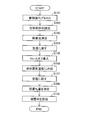
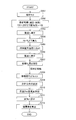
- FIG. 8 is a diagram showing the flow of processing in the coverage analyzer according to the second embodiment of the present invention.
- the sample 8 is preferably washed and purified after being modified with a modifying material.
- Step S101 The sample 8 modified with the modifying material is set in the sample holding unit 9.
- Step S102 Setting analysis conditions for performing thermogravimetric analysis.
- the analysis conditions set here are the same as the analysis conditions when performing a general thermogravimetric analysis. That is, the temperature profile when heating the sample 8 (how many times it is heated and the temperature rising rate when heating it) is set as the analysis condition. In this step, an analysis condition for a specific surface area analysis step described later may also be set.
- Step S103 The thermogravimetric analysis unit 11 executes thermogravimetric analysis under the set analysis conditions.
- the thermogravimetric analysis unit 11 measures the mass of the sample 8 that has been heated to a predetermined temperature by the heating mechanism of the furnace 7 and that changes with heating.
- the thermogravimetric analysis unit 11 gives the measured mass change amount of the sample 8 to the system control unit 12 as the mass of the modifier desorbed from the surface of the sample 8 by heating.
- Step S104 The temperature of the sample 8 is returned to room temperature by stopping the heating of the sample 8 by the heating mechanism.
- thermogravimetric analysis process a series of processes from step S101 to step S104 is expressed as a thermogravimetric analysis process.
- the sample 8 after the thermogravimetric analysis step is in an unmodified state because the modifying material whose surface has been modified is detached by heating.
- Step S105 After the thermogravimetric analysis step is completed, an inert gas is introduced into the furnace 7.
- the system control unit 12 opens the nitrogen gas valve 2 and the helium gas valve 3 to introduce a mixed gas of He gas and N 2 gas into the furnace 7.
- Step S106 The sample 8 is cooled by opening the liquid nitrogen valve 5 and circulating liquid nitrogen through the pipe. By cooling the surface of the sample 8 in the furnace 7 into which the N 2 gas has been introduced, N 2 molecules are adsorbed.
- Step S107 The sample 8 is returned to room temperature by closing the liquid nitrogen valve 5 and stopping the flow of liquid nitrogen.
- Step S108 The specific surface area analysis unit 15 measures the specific surface area of the sample 8 based on the amount of N 2 molecules adsorbed on the sample 8 (adsorption N 2 amount), and gives the measured specific surface area to the system control unit 12.
- step S105 a series of processes from step S105 to step S108 is expressed as a specific surface area analysis process here.
- Step S109 The system control unit 12 covers the coverage of the sample 8 based on the mass of the modifying material obtained by the thermogravimetric analysis process and the specific surface area of the unmodified sample 8 obtained by the specific surface area analysis process. Is calculated. That is, step S109 is a calculation process for calculating the coverage of the sample 8.
- the system control unit 12 calculates the number of molecules of the modifying material that has modified the sample 8 by dividing the mass of the modifying material obtained by the thermogravimetric analysis step by the molecular weight of the modifying material. .
- the system control unit 12 divides the specific surface area of the unmodified sample 8 obtained by the specific surface area analysis step by the concentration of the reaction site on the surface of the sample 8. By this division, the system control unit 12 calculates the number of reaction sites included in the unmodified sample 8.
- the reaction site means a functional group to which the modifier is bonded or adsorbed on the surface of the sample 8. If the sample 8 is silica, SiOH existing on the outermost surface of silica is expressed as a reaction site.
- the concentration of reaction sites means the density of reaction sites distributed on the surface of the sample 8. If the sample 8 is a silica particle, the concentration of the reaction site (SiOH) is 1/25 ⁇ 10 ⁇ 20 m 2 (25 2 ).
- the system control unit 12 calculates the ratio of the modifier to the reaction site by dividing the number of molecules of the modifier obtained by the above calculation by the number of reaction sites of the sample 8.
- the ratio of the modifying material to the reaction site is equivalent to the coverage of the sample 8 modified by the modifying material.
- the coverage of the sample 8 modified with the modifying material is calculated.
- the sample 8 may be further subjected to thermogravimetric analysis and specific surface area analysis.
- the sample 8 modified with the modifying material is subjected to thermogravimetric analysis, and the mass of the modifying material modifying the sample 8 is measured. Therefore, the mass of the modifying material can be analyzed with high accuracy. Then, the specific surface area of the unmodified sample 8 is measured, and the coverage of the sample 8 modified with the modifying material is measured based on the specific surface area and the mass of the modifying material, so that the coverage is accurately calculated. Is possible.
- thermogravimetric analysis is first performed, and then specific surface area analysis is performed.
- step S ⁇ b> 104 when the thermogravimetric analysis is completed (step S ⁇ b> 104), the modifying material that has modified the sample 8 and other adsorbates are desorbed from the surface of the sample 8. That is, it can be said that the sample 8 is automatically in a clean unmodified state by performing thermogravimetric analysis. Therefore, it is not necessary to perform the processing for the specific surface area analysis on the sample 8, and the sample 8 after the thermogravimetric analysis can be directly used for the specific surface area analysis. As a result, the coverage analysis process can be simplified.
- thermogravimetric analysis when the thermogravimetric analysis is completed, the sample 8 is sufficiently dry. Therefore, when a normal specific surface area analysis is performed, a pre-drying step necessary as a pretreatment can be omitted.
- This pre-drying process generally includes heating of the sample and purging of atmospheric gas, and takes a long time of several hours to one day.
- the coverage analysis apparatus 20 and the coverage analysis method according to the present embodiment can significantly reduce the time required to analyze the coverage. In addition, since the time required for coverage analysis can be shortened, cost reduction is also realized.
- the sample 8 can be continuously analyzed by thermogravimetric analysis and specific surface area analysis, so that the same sample can be continuously analyzed, thereby improving the analysis accuracy.
- the sample holding unit 9 includes a cooling mechanism capable of cooling the sample 8, so that the sample 8 is not moved from the sample holding unit 9, that is, the sample Specific surface area analysis can be performed without exposing 8 to the atmosphere.
- the sample holding unit 9 includes a cooling mechanism capable of cooling the sample 8, so that the sample 8 is not moved from the sample holding unit 9, that is, the sample Specific surface area analysis can be performed without exposing 8 to the atmosphere.
- FIG. 3 A third embodiment of the present invention will be described with reference to FIG. Also in this embodiment, the coverage analysis apparatus 20 is used.
- the present embodiment is different from the above-described first embodiment in that the thermogravimetric analysis is performed after the specific surface area analysis is first performed.
- Step S201 The unmodified sample 8 is set in the sample holder 9.
- Step S202 Sample 8 is pre-dried. Specifically, the sample 8 is heated to 100 ° C. to 200 ° C. by the heating mechanism of the furnace 7. An appropriate temperature may be selected as the sample temperature in the preliminary drying step according to the sample. Further, the pre-drying step may be performed in a state where the inside of the furnace 7 is decompressed, or the pre-drying step may be performed while purging the atmospheric gas.
- Step S203 By stopping the heating of the sample 8 by the heating mechanism, the sample 8 is returned to room temperature.
- Step S204 An inert gas is introduced into the furnace 7, and the inside of the furnace 7 is brought to a predetermined pressure.
- the system control unit 12 introduces a mixed gas of He and N 2 into the furnace 7 by opening the nitrogen gas valve 2 and the helium gas valve 3.
- Step S205 The sample 8 is cooled by opening the liquid nitrogen valve 5 and circulating liquid nitrogen through the pipe. By cooling the surface of the sample 8 in the furnace 7 into which the N 2 gas has been introduced, N 2 molecules are adsorbed.
- Step S206 The liquid nitrogen valve 5 is closed to stop the flow of liquid nitrogen, thereby returning the sample 8 to room temperature.
- Step S207 The specific surface area analysis unit 15 measures the specific surface area of the sample 8 based on the amount of N 2 molecules adsorbed on the sample 8, and gives the measured specific surface area to the system control unit 12.
- step S201 to step S207 a series of processes from step S201 to step S207 are expressed here as a specific surface area analysis process.
- the specific surface area analysis step is completed, the unmodified sample 8 is taken out from the coverage analyzer 20 and the modifier is modified. Then, the sample 8 after being modified with the modifying material is washed and purified.
- Step S208 The sample 8 modified with the modifying material is set in the sample holder 9.
- Step S209 Set analysis conditions for executing thermogravimetric analysis.
- the analysis conditions to be set are the same as in the first embodiment.
- Step S210 The thermogravimetric analysis unit 11 performs a thermogravimetric analysis under the set analysis conditions.
- the thermogravimetric analysis unit 11 measures the mass of the sample 8 that has been heated to a predetermined temperature by the heating mechanism of the furnace 7 that changes with heating.
- the thermogravimetric analysis unit 11 gives the measured mass change amount of the sample 8 to the system control unit 12 as the mass of the modifier desorbed from the surface of the sample 8 by heating.
- Step S211 The temperature of the sample 8 is returned to room temperature by stopping the heating of the sample 8 by the heating mechanism.
- thermogravimetric analysis process a series of processes from step S208 to step S211 are expressed as a thermogravimetric analysis process here.
- Step S212 The system control unit 12 determines the coverage of the sample 8 based on the specific surface area of the unmodified sample 8 obtained by the specific surface area analysis step and the mass of the modifying material obtained by the thermogravimetric analysis step. calculate.
- the process by which the system control unit 12 calculates the coverage is the same as step S109 in the first embodiment.
- the coverage analysis apparatus 20 and the coverage analysis method according to the third embodiment of the present invention calculate the coverage of the sample 8 that is modified by the modifier.
- Patent Documents 1 to 6 and Non-Patent Documents 1 to 3 are used. It goes without saying that the purification process according to the present embodiment can be applied to the purification process of modified nanoparticles using the modification reaction shown in FIG. It goes without saying that the modification reaction itself and the combination of nanoparticles, modifiers, solvents, etc. used in the modification reaction are not particularly limited.
- Example 1 ⁇ Modification reaction> First, in a 50 mL (L; liter) volume autoclave, 30 mg of nano silica having a primary particle diameter of 30 nm as nanoparticles, 11.6 ⁇ L of octadecyltrimethoxysilane as a modifier, and liquid carbon dioxide (liquid CO 2 ) as a solvent 16 g was charged and sealed.
- liquid CO 2 liquid carbon dioxide
- reaction liquid in the autoclave is heated and pressurized to 40 ° C. and 7.3 MPa to react with liquid CO 2 in a supercritical state for 0.5 hours, thereby producing modified nanosilica as a product (modified nanoparticle). did. Then, it returned to normal temperature normal pressure.
- reaction product in the autoclave was filtered through a PVDF (polyvinylidene fluoride) filter having a pore size of 200 nm using methanol and chloroform as washing liquids.
- PVDF polyvinylidene fluoride
- GC-Mass decomposition gas chromatography mass spectrometer
- the peak of the unreacted modifier is present at about 250 to 400 ° C. as shown in FIG. In FIG. 4, since there are almost no peaks other than a small peak of 100 ° C. or less and a large peak of 400 to 600 ° C., it was found that there is almost no unreacted modifier.
- Example 2 ⁇ Modification reaction> and ⁇ impurity capture>
- Example 1 the same reaction and operation as in Example 1 were performed except that 1.2 g of glass wool was added instead of dummy silica as a trap material in the ⁇ impurity trapping> step, which is the initial stage of the purification process. went.
- this reaction solution was divided into two, and one was dried under reduced pressure in the same manner as in Example 1 to recover powdered modified nanosilica as product (I). Further, the other is dried by heating at 150 ° C. for 5 minutes under a reduced pressure of 1 ⁇ 10 ⁇ 2 MPa with a desiccator via a vacuum pump, whereby the powdery modified nano silica is obtained as a product (II). It was collected.
- Example 1 As a result, as in Example 1, a small peak was confirmed at 100 ° C. or lower, and no significant peak was confirmed except that a large peak was observed at 400 to 600 ° C. This confirmed that there was almost no unreacted modifier.
- the obtained product (II) was heated at 20 ° C./min using GC-Mass in the same manner as the product (II), and the ionic strength between 50 and 800 ° C. was measured.
- the purity of the product (II) derived from the peak area of the GC chart is 93.6%, and the purity can be further increased by drying while heating after removing the trap material, and the impurity component is extremely high. It was found that modified nanosilica with very little purity was obtained.
- Example 3 ⁇ Modification reaction>
- the same autoclave as in Example 1 was used, through a valve, a silica column with a diameter of 3 cm and a length of 25 cm (a column in which a pressure resistant stainless steel vessel was filled with 250 g of silica particles with a diameter of 65 ⁇ m).
- a closed state in the same manner as in Example 1, 30 mg of nano silica having a primary particle diameter of 30 nm, 11.6 ⁇ L of octadecyltrimethoxysilane, and 16 g of liquid CO 2 were charged and sealed to 40 ° C. and up to 7.3 MPa.
- the reaction was carried out for 0.5 hour by heating and pressurizing to bring liquid CO 2 into a supercritical state.
- the modified nanosilica was recovered as a powder by heating and drying the reaction solution under reduced pressure.
- Example 1 As a result, as in Example 1, a small peak was confirmed at 100 ° C. or lower, and no significant peak was confirmed except that a large peak was observed at 400 to 600 ° C. This confirmed that there was almost no unreacted modifier.
- the large peak at 50 to 150 ° C. includes the peak at 100 ° C. or lower as seen in Examples 1 to 3, which includes low-boiling impurities such as water and methanol, and other low-boiling components. It shows that it contains.
- a small peak at 250 to 400 ° C. indicates an unreacted modifying agent (not bonded and fixed to the nanosilica surface) incorporated between the agglomerated modified nanoparticles.
- the purity derived from the peak area of the GC chart shown in FIG. 6 was 51%, and it was confirmed that the purity was clearly lower than the modified nanoparticles obtained in Examples 1 to 3.
- Example 4 ⁇ Modification reaction>
- the same operation as in Example 1 was performed except that 30 mg of titanium oxide (TiO 2 ) having a primary particle diameter of 30 nm was used and 11.6 ⁇ L of dimethoxydiphenylsilane was used as a modifier.
- modified titania was produced as a product (modified nanoparticle).
- this composite polymer was spin-coated on a silicon substrate and dried at 120 ° C. for 2 hours to prepare a composite polymer thin film having a thickness of 5 ⁇ m.
- the obtained composite polymer thin film (film thickness: 5 ⁇ m) was colorless and transparent, and the refractive index was 1.83. Therefore, according to the present Example, it turned out that the composite polymer which has a high refractive index can be obtained by using the said modified nanoparticle.
- Example 5 ⁇ Modification reaction> In Example 4, except that 11.6 ⁇ L of aminopropyltrimethoxysilane was used as a modifying agent, the same operation as in Example 4 was performed to produce modified titania as a product (modified nanoparticle).
- the composite polymer was spin-coated on a silicon substrate and dried at 90 ° C. for 1 hour to prepare a composite polymer thin film having a thickness of 5 ⁇ m.
- the obtained composite polymer thin film (film thickness: 5 ⁇ m) was colorless and transparent, and the refractive index was 2.15. Therefore, according to the present Example, it turned out that the composite polymer which has a high refractive index can be obtained by using the said modified nanoparticle.
- Example 6 ⁇ Modification reaction>
- the same operation as in Example 1 was performed except that 30 mg of aluminum oxide (Al 2 O 3 ) having a primary particle size of 30 nm was used and 11.6 ⁇ L of dimethoxydiphenylsilane was used as a modifier. And modified alumina was produced as a product (modified nanoparticles).
- this composite polymer was spin-coated on a silicon substrate and dried at 120 ° C. for 2 hours to produce a small piece of composite polymer piece having a diameter of 1 cm and a thickness of 1 mm.
- the obtained composite polymer piece was colorless and transparent, and the thermal conductivity was 4.5 W / m ⁇ k. Therefore, according to the present Example, it turned out that the composite polymer which has high heat conductivity can be obtained by using the said modified nanoparticle.
- Example 7 The coverage was analyzed by thermogravimetric analysis and specific surface area analysis.
- Example modification Silica fine particles having an average particle diameter of 200 nm were used as a sample, and OTS was used as a modifier.
- a sample with a modification reaction time of 0.1 hour is a sample 8a, a sample with a 0.5 hour sample 8b, a sample with 1 hour sample 8c, a sample with 3 hours sample 8d, and a sample with 5 hours sample This is denoted as sample 8e.
- sample 8e a sample with 5 hours sample
- Thermogravimetric analysis was performed with Rigaku's Thermo plus. First, 10.453 g of sample 8a was weighed and placed in a platinum sample pan, set on a balance, and then heated to 700 ° C. at a rate of temperature increase of 20 ° C./min while flowing N 2 gas to change the mass of sample 8a. was measured. As a result, a plurality of mass change locations were detected, and each generated gas was subjected to mass analysis, and the mass change amount of the component bonded and fixed to the silica particles was measured as the mass of the modifier.
- FIG. 10A shows the results of the coverage ratio analysis performed on the sample 8b, the sample 8c, the sample 8d, and the sample 8e.
- FIG. 10 (b) shows a plot of the coverage of each of the samples 8a to 8e against the modification reaction time.
- the coverage of the sample 8 with the modifying material was determined only by specific surface area analysis. Specifically, the specific surface area of the unmodified sample was obtained by performing specific surface analysis on the unmodified sample. Next, the specific surface area of the unmodified region (unmodified region) in the post-modification sample was obtained by performing a specific surface area analysis on the sample modified with the modifier.
- the specific surface area of the modified region (modified region) in the modified sample was calculated by subtracting the specific surface area of the unmodified region in the modified sample from the specific surface area of the unmodified sample ((a in FIG. 11). ) Specific surface area at the time of modification Finally, the coverage in the modified sample was calculated by dividing the specific surface area of the modified region by the specific surface area of the unmodified sample.
- FIG. 11 (a) shows the specific surface area and coverage at the time of modification in five samples having a modification reaction time of 0.1 hour, 0.5 hour, 1 hour, 3 hours, and 5 hours as in the example. . Moreover, the figure which plotted the coverage of each sample with respect to modification reaction time is shown in FIG.11 (b).
- Comparative Example 2 showed a higher coverage. Moreover, in Example 7, it detected that the increase rate of the coverage rate differed in the area
- the method for purifying modified microparticles according to aspect 1 of the present invention includes a solvent comprising a microparticle having a primary particle diameter of less than 100 nm, to which a surface modifier is bound and fixed, and a compound that is not bonded and fixed to the surface of the microparticle. In a supercritical state, it is brought into contact with a trap material larger than the fine particles, and the compound contained in the solvent that is not bonded and fixed to the surface of the fine particles is trapped and removed by the trap material.
- Fine particles with a primary particle diameter of less than 100 nm are difficult to filter and centrifuge. For this reason, a purification process is an important element in order to obtain modified fine particles with very few impurities.
- Such fine particles are usually agglomerated, and when the fine particles and the modifier are reacted in a normal solvent, the agglomeration of the fine particles is hardly solved and the agglomerated state of the fine particles is maintained. For this reason, in this case, impurities such as unreacted modifiers, by-products and solvents are taken into the voids of the aggregates of fine particles whose surfaces are modified.
- the modification reaction when carried out in a supercritical state, even if the fine particles are aggregated to form secondary particles or tertiary particles, the supercritical fluid and the modifier are not allowed to react with the secondary particles or tertiary particles. It penetrates between the formed fine particles. As a result, the fine particles, which are primary particles, react with the modifying agent, and the modifying agent is bonded and fixed to the surface of each fine particle to form the modified fine particles. As a result, the modified fine particles are dispersed as primary particles and impurities such as unreacted modifiers and by-products are present around the modified fine particles.
- the impurity components are eluted, and (a) becomes a plasticizer, (b) the eluted impurity components are added as unreacted monomers or added. It causes adverse effects such as generating unnecessary substances and bubbles by reacting with the agent, (c) leading to a decrease in durability, and (d) changing characteristics.
- the modified fine particles remain in a primary particle or a state in which the solvent is dispersed in a supercritical state by bringing the solvent into contact with a trap material larger than the fine particles, Impurities can be trapped and removed in the trap material.
- the method for purifying modified microparticles according to Aspect 2 of the present invention is the method for purifying modified microparticles according to Aspect 1, wherein the surface modifier is bound and fixed, and the primary particle diameter is less than 100 nm, and the compound is not bound and fixed to the surface of the microparticle.
- the modified fine particles are dispersed as primary particles, or in a state close to it, Impurities can be trapped.
- the trap material in the method for purifying modified fine particles according to aspect 3 of the present invention, can be removed by filtration. As described above, the trap material is larger than the fine particles and can be easily removed by filtration.
- the method for purifying modified microparticles according to Aspect 4 of the present invention is the method for purifying modified microparticles according to Aspect 1, wherein the surface modifier is bound and fixed, the primary particle diameter is less than 100 nm, and the compound is not bound and fixed to the surface of the microparticle A method of trapping and removing a compound that is not bonded and fixed to the surface of the fine particles by passing a supercritical solvent containing the above through a container containing the trap material.
- impurities contained in the solvent can be trapped and removed by the trap material without separately removing the trap material from the solvent. That is, the trapping of the impurities and the removal of the impurities from the solvent can be performed simultaneously.
- the trapping material is preferably a particle having a larger diameter than the fine particles and having a hydrophilic surface.
- examples of the trap material include silica and alumina.
- Silica and alumina have a large specific surface area, excellent adsorption ability, heat resistance and water resistance, and adsorb many organic compounds that have functional groups that can be assumed to be used as modifiers. Therefore, it is suitable as a trap material.
- the trap material is preferably made of the same material as the fine particles.
- a trap material made of the same material as the fine particles is brought into contact with an unreacted modifier contained in the solvent, whereby the unreacted modifier is bound and fixed to the surface of the trap material. can do.
- the trap material is fibrous, and the removal of the trap material may be performed by taking out the trap material from the solvent. .
- the trap material in the eighth aspect includes, for example, glass wool.
- the trap material is formed in a fiber shape and the surface area is increased, so that the impurities can be easily trapped in the fiber network.
- the trap material can be easily taken out from the solvent without filtration.
- the compound contained in the solvent that is not bonded and fixed to the surface of the fine particles is trapped and removed by the trap material. Thereafter, it is preferable to include a step of drying the fine particles to which the surface modifier is bound and fixed under reduced pressure.
- the modified fine particles can be efficiently dried, and the modified fine particles can be recovered as powdered modified fine particles.
- the drying is preferably heat drying.
- the solvent used as the supercritical fluid is any one selected from the group consisting of liquid carbon dioxide, methanol, ethanol, acetone, and water.
- a kind of solvent is preferable because it is easy to handle in terms of temperature and pressure.
- carbon dioxide or methanol is preferably used because it has high solubility in various substances and can be handled at a relatively low temperature and low pressure.
- Methanol is suitable when the modifier is highly polar.
- the method for producing modified fine particles according to the thirteenth aspect of the present invention brings the fine particles having a primary particle diameter of less than 100 nm into contact with a surface modifier in a supercritical solvent.
- a purification step in which a solvent is brought into contact with a trap material larger than the fine particles in a supercritical state to trap and remove compounds contained in the solvent that are not bonded and fixed to the surface of the fine particles with the trap material. Including.
- the supercritical fluid and the modifier permeate between the aggregated microparticles even if the microparticles aggregate to form secondary particles or tertiary particles. Are bonded and fixed to the surface of each fine particle.
- the obtained modified fine particles are dispersed as primary particles, and impurities such as unreacted modifiers and by-products are present around them. Therefore, in this state, when a trap material is allowed to coexist, impurities such as unreacted modifiers can be efficiently removed from the system.
- the coating ratio of the modifier on the surface of the fine particles is high, the dispersibility is improved, so that it is difficult to aggregate, and as a result, it becomes more difficult to take in impurities.
- the high dispersibility leads to an improvement in the filling rate when the modified fine particles are composited with, for example, a polymer.
- the method for producing modified fine particles according to aspect 14 of the present invention further includes a step of returning the solvent to room temperature and normal pressure after the modification reaction step in the aspect 13, wherein the purification step returns the normal temperature to normal pressure.
- the solvent is brought into a supercritical state again to trap the compound that is not bonded and fixed to the surface of the fine particles, and the step of removing the trap material from the solvent. You may go out.
- the modified fine particles remain in the primary particles or in a state of being dispersed as a state close to the primary particles, The impurities can be trapped.
- the method for producing modified microparticles according to Aspect 14 of the present invention is the method for producing modified microparticles according to Aspect 13, wherein in the purification step, the surface modifier is bound and fixed, and the primary particle diameter is less than 100 nm and the surface of the microparticle is bound and fixed.
- the above-mentioned solvent in a supercritical state containing an untreated compound is connected to the reaction vessel used for the modification reaction, and the inside of the container containing the trap material is returned to room temperature and normal pressure after the modification reaction step.
- it may be a method of trapping and removing a compound that is not bonded and fixed to the surface of the fine particles by passing it in a supercritical state.
- impurities contained in the solvent can be trapped and removed by the trap material without separately removing the trap material from the solvent. That is, the trapping of the impurities and the removal of the impurities from the solvent can be performed simultaneously.
- the modified fine particle according to the sixteenth aspect of the present invention is a modified fine particle in which a surface modifier is bound and fixed on the surface of a fine particle having a primary particle diameter of less than 100 nm, and the impurity component ratio measured by thermal decomposition gas chromatography mass spectrometry Is less than 30%.
- the impurity component ratio in the aspect 16 is preferably less than 10%.
- the impurities in the aggregated fine particles can be removed, it is possible to provide modified fine particles having a very small impurity component while having a primary particle diameter of less than 100 nm.
- the functional material according to Aspect 18 of the present invention includes the modified fine particles according to Aspect 16 or 17, and is solid or liquid.
- the functional material according to Aspect 19 of the present invention is preferably obtained by dispersing the modified fine particles in a polymer in the Aspect 18.
- optical member according to aspect 20 of the present invention is made of the functional material according to aspect 18 or 19.
- the heat transfer member according to aspect 21 of the present invention is made of the functional material according to aspect 18 or 19.
- the impurity components are eluted and, as described above, have adverse effects as shown in (a) to (d).
- modified fine particles having an extremely small amount of impurity components are used, and thus there is no risk of such an adverse effect.
- the higher affinity between the modified fine particles and the base material such as polymer is in the direction of increasing the interface area, that is, in the direction of decreasing the particle diameter. Therefore, in order to disperse many fine particles in the base material, it is preferable to reduce the particle diameter.
- a coverage analyzer is a coverage analyzer that analyzes a coverage representing a ratio of a region modified with a modifier on the surface of a sample modified with the modifier.
- Thermogravimetric analysis means for thermogravimetrically analyzing the sample in a state modified with a modifying material and measuring the mass of the modifying material modifying the surface of the sample; and the sample in a state not modified by the modifying material
- Specific surface area analysis means for measuring the specific surface area of the surface of the sample, the mass of the modifying material measured by the thermogravimetric analysis means, and the specific surface area of the sample measured by the specific surface area analysis means
- a control means for calculating the coverage based on the above.
- the mass of the modifying material modifying the sample by performing thermogravimetric analysis on the sample modified with the modifying material (hereinafter also referred to as a modified sample). Measure.
- the mass of the modifier since the mass of the modifier is directly measured, the mass of the modifier can be obtained with high accuracy.
- the specific surface area of a sample that has not been modified with a modifying material (hereinafter also referred to as an unmodified sample) is measured.
- the specific surface area analysis is performed on the unmodified sample, the specific surface area of the sample can be obtained with high accuracy.
- the coverage of the sample with the modifying material is calculated.
- the coverage analysis apparatus and the coverage analysis method based on the mass of the modified material obtained accurately and the specific surface area of the unmodified sample, Since the coverage is calculated, a highly accurate coverage can be calculated. Further, according to the coverage analyzer according to one embodiment of the present invention, both the thermogravimetric analysis and the specific surface area analysis can be performed in one analyzer, so that the coverage calculation process can be simplified. it can.
- the coverage analysis apparatus is the aspect 22 according to the above aspect 22, wherein the control means causes the thermogravimetric analysis means to measure the mass of the modifying material, and then causes the specific surface area analysis means to compare the ratio of the sample. It is preferable to measure the surface area.
- the specific surface area of the unmodified sample is measured by specific surface area analysis.
- thermogravimetric analysis the sample after modification is heated to a high temperature. For this reason, the modifier and other deposits are desorbed by high-temperature heating, and the sample after thermogravimetric analysis has a clean surface from which these have been removed. Then, a specific surface area analysis is performed on the clean sample.
- a sample having a clean surface can be obtained without requiring a separate process for cleaning the sample surface for specific surface area analysis.
- thermogravimetric analysis is performed before the specific surface area analysis is performed. Therefore, the sample to be subjected to the specific surface area analysis is heated at a high temperature by thermogravimetric analysis. As a result, the pretreatment for drying and degassing the sample is not required before the specific surface area analysis. As a result, the time required for the coverage analysis can be greatly shortened. Further, along with the fact that the time required for the coverage analysis can be shortened, the cost can also be reduced.
- the coverage analysis method according to one embodiment of the present invention also has the same effect.
- the coverage analyzer can perform both thermogravimetric analysis and specific surface area analysis in one analyzer, a sample with a clean surface after thermogravimetric analysis is put into the atmosphere. It is possible to perform a specific surface area analysis without exposure. Therefore, it is possible to analyze the specific surface area of the sample not modified with the modifying material with high accuracy, and consequently, the coverage can be analyzed with higher accuracy.
- the coverage analysis apparatus is the above aspect 22 or 23, wherein the thermogravimetry is measured by the thermogravimetric analysis means and the specific surface area is measured by the specific surface area analysis means. It is preferable that the apparatus further includes a sample holding unit that holds the sample, and the sample holding unit includes a cooling unit that cools the sample when the specific surface area of the sample is measured by the specific surface area analyzing unit.
- the sample holding unit holds the sample in any case of measuring the thermogravimetric weight of the sample and measuring the specific surface area.
- the cooling means provided in the sample holder cools the sample through the sample holder when measuring the specific surface area. Therefore, the sample can be sufficiently cooled when the specific surface area analyzing means adsorbs gas on the sample surface to increase the specific surface area.
- thermogravimetric analysis and the specific surface area analysis can be performed while the sample is held in the sample holding unit, that is, without moving the sample from the sample holding unit. Analysis can be performed. Thereby, the analysis process can be simplified. Further, since there is no need to move the sample under analysis, thermogravimetric analysis and specific surface area analysis can be performed without exposing the sample to the atmosphere. Thereby, the precision at the time of analyzing a coverage can be improved further.
- thermogravimetric analysis means performs thermogravimetric analysis on the sample modified with the modifying material, and extracts components desorbed from the sample.
- a thermogravimetric analyzer that measures mass; and a mass analyzer that performs mass analysis of components desorbed from the sample and extracts the mass of the modifying material from the mass measured by the thermogravimetric analyzer. Is preferred.
- the coverage analyzer is the thermogravimetric analysis of the modified sample by the thermogravimetric analysis unit of the thermogravimetric analysis unit, and the mass of the component desorbed from the sample is measured. To do.
- the mass analysis unit of the thermogravimetric analysis means the component desorbed from the sample is subjected to mass analysis, and the mass of the modifying material is extracted from the mass measured by the thermogravimetric analysis unit.
- thermogravimetric analysis the mass of the component desorbed from the sample after modification is obtained, but this mass may also include the mass of components other than the modifier attached to the sample after modification.
- the thermogravimetric analysis unit is caused to execute both the thermogravimetric analysis by the thermogravimetric analysis unit and the mass analysis by the mass analysis unit. It is possible to extract well. Therefore, the coverage can be calculated with higher accuracy based on the mass of the modifying material obtained with higher accuracy.
- the coverage analysis method is a coverage analysis method for analyzing a coverage representing a ratio of a region modified with a modifier on the surface of a sample modified with the modifier, Thermogravimetric analysis of the sample modified with the modifier, and measuring the mass of the modifier modifying the surface of the sample, and the sample not modified with the modifier
- Specific surface area analysis step for measuring the specific surface area of the surface of the sample, the mass of the modifying material measured by the thermogravimetric analysis means, and the specific surface area of the sample measured by the specific surface area analysis means And a calculation step for calculating the coverage based on the above.
- the coverage ratio represents the ratio of the region modified with the modifier to the region not modified with the modifier on the surface of the sample modified with the modifier.
- the specific surface area deriving step is preferably performed after the thermogravimetric analysis step.
- the modified fine particles obtained by the method of the present invention have very few impurity components and can be suitably used as functional materials such as materials for optical members and heat transfer members.
- the present invention can be suitably used as a coverage analysis apparatus and a coverage analysis method for deriving the coverage of a modifying substance modified on the surface of a base material.
Landscapes
- Chemical & Material Sciences (AREA)
- Chemical Kinetics & Catalysis (AREA)
- Analytical Chemistry (AREA)
- Health & Medical Sciences (AREA)
- Life Sciences & Earth Sciences (AREA)
- General Physics & Mathematics (AREA)
- Biochemistry (AREA)
- General Health & Medical Sciences (AREA)
- Physics & Mathematics (AREA)
- Immunology (AREA)
- Pathology (AREA)
- Medicinal Chemistry (AREA)
- Polymers & Plastics (AREA)
- Organic Chemistry (AREA)
- Engineering & Computer Science (AREA)
- Wood Science & Technology (AREA)
- Physical Or Chemical Processes And Apparatus (AREA)
Abstract
Cette invention concerne un solvant contenant des nanoparticules ayant un diamètre de particule primaire inférieur à 100 nm et auxquelles un agent de modification de surface est lié et fixé, et un composé non lié et fixé à la surface des nanoparticules. A l'état supercritique, ce solvant est mis en contact avec un matériau piégeur tel que des particules factices plus volumineuses que les nanoparticules, et les composés contenus dans le solvant et non liés et fixés à la surface des nanoparticules sont piégés par le matériau piégeur et éliminés.
Priority Applications (1)
| Application Number | Priority Date | Filing Date | Title |
|---|---|---|---|
| US14/384,329 US20150024209A1 (en) | 2012-03-12 | 2013-02-26 | Modified particle purification method and manufacturing method, modified particles, functional material, optical member, heat transfer member, and coverage rate analysis device and coverage rate analysis method |
Applications Claiming Priority (4)
| Application Number | Priority Date | Filing Date | Title |
|---|---|---|---|
| JP2012-055081 | 2012-03-12 | ||
| JP2012055081 | 2012-03-12 | ||
| JP2012143503 | 2012-06-26 | ||
| JP2012-143503 | 2012-06-26 |
Publications (1)
| Publication Number | Publication Date |
|---|---|
| WO2013136974A1 true WO2013136974A1 (fr) | 2013-09-19 |
Family
ID=49160890
Family Applications (1)
| Application Number | Title | Priority Date | Filing Date |
|---|---|---|---|
| PCT/JP2013/055000 Ceased WO2013136974A1 (fr) | 2012-03-12 | 2013-02-26 | Procédé de purification de particules modifiées et leur procédé de fabrication, particules modifiées, matériau fonctionnel, élément optique, élément de transfert thermique, dispositif d'analyse du taux de couverture et procédé associé |
Country Status (2)
| Country | Link |
|---|---|
| US (1) | US20150024209A1 (fr) |
| WO (1) | WO2013136974A1 (fr) |
Families Citing this family (4)
| Publication number | Priority date | Publication date | Assignee | Title |
|---|---|---|---|---|
| CN113237789B (zh) * | 2021-05-12 | 2023-07-28 | 雅安百图高新材料股份有限公司 | 检测氧化铝粉体表面的有机改性剂含量的方法 |
| CN115869653B (zh) * | 2022-11-28 | 2025-09-16 | 深圳市华星光电半导体显示技术有限公司 | 粒子提纯方法 |
| CN116337679B (zh) * | 2023-03-01 | 2025-11-07 | 西安航天化学动力有限公司 | 一种包覆细氧化剂中表面改性剂含量的测量方法 |
| CN117907533B (zh) * | 2023-12-22 | 2024-08-09 | 山东山田新材科研有限公司 | 一种细颗粒硅粉活性测量系统 |
Citations (6)
| Publication number | Priority date | Publication date | Assignee | Title |
|---|---|---|---|---|
| JP2003135901A (ja) * | 2001-11-01 | 2003-05-13 | Nikkiso Co Ltd | 微粉化装置 |
| JP2005052715A (ja) * | 2003-08-01 | 2005-03-03 | National Institute Of Advanced Industrial & Technology | 反応システム及び同システムに用いる微粒子捕集装置 |
| JP2005352085A (ja) * | 2004-06-09 | 2005-12-22 | Sharp Corp | 現像剤およびその製造方法 |
| JP2008221034A (ja) * | 2007-03-08 | 2008-09-25 | Konica Minolta Medical & Graphic Inc | 半導体ナノ粒子の製造方法および半導体ナノ粒子 |
| JP2009279573A (ja) * | 2008-05-26 | 2009-12-03 | 3R Corp | 超臨界二酸化炭素を含む溶液からの溶質の分離方法 |
| JP2010046625A (ja) * | 2008-08-22 | 2010-03-04 | Tohoku Univ | 超臨界水熱反応による金属・合金ナノ粒子の合成法 |
Family Cites Families (8)
| Publication number | Priority date | Publication date | Assignee | Title |
|---|---|---|---|---|
| US2302195A (en) * | 1940-01-08 | 1942-11-17 | Mid Continent Petroleum Corp | Apparatus for separating waxcontaining materials |
| US5350714A (en) * | 1993-11-08 | 1994-09-27 | Shipley Company Inc. | Point-of-use purification |
| US5896024A (en) * | 1998-03-24 | 1999-04-20 | Black & Decker, Inc. | Method and apparatus for manually selecting battery charging process |
| US6113714A (en) * | 1998-04-29 | 2000-09-05 | Eti Canada Inc. | Ammonium nitrate fuel oil blasting composition having improved water resistance |
| GB9828204D0 (en) * | 1998-12-21 | 1999-02-17 | Smithkline Beecham Plc | Process |
| FR2815540B1 (fr) * | 2000-10-19 | 2005-06-10 | Separex Sa | Procede de fabrication de tres fines particules constituees d'un principe insere dans une molecule hote |
| US6998051B2 (en) * | 2002-07-03 | 2006-02-14 | Ferro Corporation | Particles from supercritical fluid extraction of emulsion |
| US9925512B2 (en) * | 2013-03-14 | 2018-03-27 | Crititech, Inc. | Equipment assembly for and method of processing particles |
-
2013
- 2013-02-26 WO PCT/JP2013/055000 patent/WO2013136974A1/fr not_active Ceased
- 2013-02-26 US US14/384,329 patent/US20150024209A1/en not_active Abandoned
Patent Citations (6)
| Publication number | Priority date | Publication date | Assignee | Title |
|---|---|---|---|---|
| JP2003135901A (ja) * | 2001-11-01 | 2003-05-13 | Nikkiso Co Ltd | 微粉化装置 |
| JP2005052715A (ja) * | 2003-08-01 | 2005-03-03 | National Institute Of Advanced Industrial & Technology | 反応システム及び同システムに用いる微粒子捕集装置 |
| JP2005352085A (ja) * | 2004-06-09 | 2005-12-22 | Sharp Corp | 現像剤およびその製造方法 |
| JP2008221034A (ja) * | 2007-03-08 | 2008-09-25 | Konica Minolta Medical & Graphic Inc | 半導体ナノ粒子の製造方法および半導体ナノ粒子 |
| JP2009279573A (ja) * | 2008-05-26 | 2009-12-03 | 3R Corp | 超臨界二酸化炭素を含む溶液からの溶質の分離方法 |
| JP2010046625A (ja) * | 2008-08-22 | 2010-03-04 | Tohoku Univ | 超臨界水熱反応による金属・合金ナノ粒子の合成法 |
Also Published As
| Publication number | Publication date |
|---|---|
| US20150024209A1 (en) | 2015-01-22 |
Similar Documents
| Publication | Publication Date | Title |
|---|---|---|
| Amalvy et al. | Synthesis and characterization of novel film-forming vinyl polymer/silica colloidal nanocomposites | |
| Zemanian et al. | Deposition of self-assembled monolayers in mesoporous silica from supercritical fluids | |
| KR102450033B1 (ko) | 실리카 입자 | |
| Bressy et al. | New insights into the adsorption of 3-(trimethoxysilyl) propylmethacrylate on hydroxylated ZnO nanopowders | |
| Wang et al. | Influences of VTMS/SiO2 ratios on the contact angle and morphology of modified super-hydrophobic silicon dioxide material by vinyl trimethoxy silane | |
| CN107583469A (zh) | 含氨基改性纳米粒子的聚酰胺复合纳滤膜的制备方法 | |
| WO2013136974A1 (fr) | Procédé de purification de particules modifiées et leur procédé de fabrication, particules modifiées, matériau fonctionnel, élément optique, élément de transfert thermique, dispositif d'analyse du taux de couverture et procédé associé | |
| CN101358242B (zh) | 基于光子晶体的复合式生物芯片 | |
| CN103994991A (zh) | 基于毛细管整体柱的表面增强拉曼基底的制备方法 | |
| WO2008021161A2 (fr) | Procédé de modification de surface pour la réduction de la dissolution de composants sous forme de traces | |
| CN105536747B (zh) | 一种智能响应液相色谱填料及其制备方法 | |
| CN1302224A (zh) | 采用经过表面处理的干凝胶进行离子分离 | |
| Cheng et al. | Dispersion stability of Si3N4 nano-particles modified by γ-methacryloxypropyl trimethoxy silane (MAPTMS) in organic solvent | |
| US20100093021A1 (en) | Hardening of ordered films of silica colloids | |
| CN101735633A (zh) | 功能化有机/无机杂化不对称结构粒子及其合成方法 | |
| WO2017002871A1 (fr) | Procédé de réaction pour réaction en contact avec un corps poreux granulaire | |
| CN102061107A (zh) | 苯乙烯或甲基丙烯酸包覆金红石型二氧化钛的方法 | |
| JP6283847B2 (ja) | コア・シェル複合粒子の製造方法 | |
| CN108998894A (zh) | 一种超疏水MOFs纳米晶体及复合膜材料、制备方法与应用 | |
| CN101054662A (zh) | 超临界水中碳纳米管上沉积二氧化铈的制备方法 | |
| Northcott et al. | Synthesis, characterization and evaluation of mesoporous silicates for adsorption of metal ions | |
| JP7464385B2 (ja) | 中空樹脂粒子及びその製造方法 | |
| CN102672197A (zh) | 一种多用途的等离子的金纳米粒子膜的制备方法 | |
| JP2010018447A (ja) | 表面被覆多孔質酸化物粒子及び多孔質酸化物粒子の表面被覆方法 | |
| CN119744199A (zh) | 无孔杂化涂覆聚合物颗粒 |
Legal Events
| Date | Code | Title | Description |
|---|---|---|---|
| 121 | Ep: the epo has been informed by wipo that ep was designated in this application |
Ref document number: 13760517 Country of ref document: EP Kind code of ref document: A1 |
|
| NENP | Non-entry into the national phase |
Ref country code: DE |
|
| WWE | Wipo information: entry into national phase |
Ref document number: 14384329 Country of ref document: US |
|
| 122 | Ep: pct application non-entry in european phase |
Ref document number: 13760517 Country of ref document: EP Kind code of ref document: A1 |
|
| NENP | Non-entry into the national phase |
Ref country code: JP |