WO2013137003A1 - Siège de roulement à rotule et roulement à rotule correspondant - Google Patents
Siège de roulement à rotule et roulement à rotule correspondant Download PDFInfo
- Publication number
- WO2013137003A1 WO2013137003A1 PCT/JP2013/055430 JP2013055430W WO2013137003A1 WO 2013137003 A1 WO2013137003 A1 WO 2013137003A1 JP 2013055430 W JP2013055430 W JP 2013055430W WO 2013137003 A1 WO2013137003 A1 WO 2013137003A1
- Authority
- WO
- WIPO (PCT)
- Prior art keywords
- ball
- ball joint
- joint bearing
- housing
- sheet
- Prior art date
- Legal status (The legal status is an assumption and is not a legal conclusion. Google has not performed a legal analysis and makes no representation as to the accuracy of the status listed.)
- Ceased
Links
Images


Classifications
-
- F—MECHANICAL ENGINEERING; LIGHTING; HEATING; WEAPONS; BLASTING
- F16—ENGINEERING ELEMENTS AND UNITS; GENERAL MEASURES FOR PRODUCING AND MAINTAINING EFFECTIVE FUNCTIONING OF MACHINES OR INSTALLATIONS; THERMAL INSULATION IN GENERAL
- F16C—SHAFTS; FLEXIBLE SHAFTS; ELEMENTS OR CRANKSHAFT MECHANISMS; ROTARY BODIES OTHER THAN GEARING ELEMENTS; BEARINGS
- F16C11/00—Pivots; Pivotal connections
- F16C11/04—Pivotal connections
- F16C11/06—Ball-joints; Other joints having more than one degree of angular freedom, i.e. universal joints
- F16C11/0619—Ball-joints; Other joints having more than one degree of angular freedom, i.e. universal joints the female part comprising a blind socket receiving the male part
- F16C11/0623—Construction or details of the socket member
- F16C11/0628—Construction or details of the socket member with linings
- F16C11/0633—Construction or details of the socket member with linings the linings being made of plastics
- F16C11/0638—Construction or details of the socket member with linings the linings being made of plastics characterised by geometrical details
-
- F—MECHANICAL ENGINEERING; LIGHTING; HEATING; WEAPONS; BLASTING
- F16—ENGINEERING ELEMENTS AND UNITS; GENERAL MEASURES FOR PRODUCING AND MAINTAINING EFFECTIVE FUNCTIONING OF MACHINES OR INSTALLATIONS; THERMAL INSULATION IN GENERAL
- F16C—SHAFTS; FLEXIBLE SHAFTS; ELEMENTS OR CRANKSHAFT MECHANISMS; ROTARY BODIES OTHER THAN GEARING ELEMENTS; BEARINGS
- F16C11/00—Pivots; Pivotal connections
- F16C11/04—Pivotal connections
- F16C11/06—Ball-joints; Other joints having more than one degree of angular freedom, i.e. universal joints
-
- Y—GENERAL TAGGING OF NEW TECHNOLOGICAL DEVELOPMENTS; GENERAL TAGGING OF CROSS-SECTIONAL TECHNOLOGIES SPANNING OVER SEVERAL SECTIONS OF THE IPC; TECHNICAL SUBJECTS COVERED BY FORMER USPC CROSS-REFERENCE ART COLLECTIONS [XRACs] AND DIGESTS
- Y10—TECHNICAL SUBJECTS COVERED BY FORMER USPC
- Y10T—TECHNICAL SUBJECTS COVERED BY FORMER US CLASSIFICATION
- Y10T403/00—Joints and connections
- Y10T403/32—Articulated members
- Y10T403/32606—Pivoted
- Y10T403/32631—Universal ball and socket
Definitions
- the present invention relates to a ball joint bearing seat and a ball joint bearing in which a housing portion for slidably housing a spherical ball portion formed at the tip of a shaft-shaped stud portion is held in a cast housing.
- the present invention relates to a ball joint including a seat.
- a ball joint is used in a suspension mechanism (suspension device) and a steering mechanism (steering device) in a vehicle such as an automobile in order to movably connect shaft-shaped components to each other.
- the ball joint is mainly configured such that a substantially spherical ball portion formed at a tip end portion of a shaft-like stud is slidably accommodated in a cylindrical bearing seat held in a cast housing.
- the bearing sheet is included integrally with the molding of the housing by being previously disposed as a core in the mold at the time of casting molding (die casting) of the housing.
- the present invention has been made in order to address the above-described problems, and its purpose is to simplify the process of joining the housing and the bearing seat by facilitating filling of the softened or melted material into the undercut portion, and the entire ball joint. It is an object of the present invention to provide a ball joint bearing sheet that easily secures the required rigidity, and a ball joint including the ball joint bearing sheet.
- a feature of the present invention is that a spherical ball portion formed of a cylindrical body and formed at the tip end portion of a shaft-shaped stud portion is slidably accommodated in the cylindrical body.
- the ball joint bearing seat held in the housing has a groove-shaped undercut portion on the outer peripheral surface in contact with the housing, and the undercut portion has a width relative to the width of the opening portion opened on the outer peripheral surface in contact with the housing. That is, at least a part of the width on the bottom side is formed wide and at a depth shallower than the width of the opening.
- the ball joint bearing seat is formed such that at least a part of the width of the bottom side is wider than the width of the opening on the outer peripheral surface in contact with the housing. It has a groove-like undercut portion formed with a depth shallower than the width of the opening.
- the ball joint bearing sheet has a groove depth in the undercut portion corresponding to the width of the groove opening portion, so that it is excessively deep with respect to the width of the opening portion. Defects can be prevented.
- the ball joint bearing sheet can improve the coupling force to the housing, and as a result, the rigidity required for the ball joint can be easily ensured.
- the undercut portion is open along at least one end of the cylindrical body along the circumferential direction of the cylindrical body. That is to be formed.
- the ball joint bearing sheet is configured such that the undercut portion is open at at least one end of both ends of the cylindrical body and the circumference of the cylindrical body. Since it is formed along the direction, it is easy to perform casting such as die casting of a ball joint bearing sheet having an undercut portion that has an undercut shape through the opening.
- the opening is formed by notching an end portion of a cylindrical body in which an undercut portion is formed.
- the ball joint bearing sheet is formed by notching the end of the cylindrical body on the side where the undercut portion is formed.
- another feature of the present invention is that, in the ball joint bearing sheet, at least three or more openings are arranged uniformly along the circumferential direction of the cylindrical body.
- the ball joint bearing seat since the ball joint bearing seat has at least three or more openings uniformly arranged along the circumferential direction of the cylindrical body, the ball joint bearing seat is even with respect to the housing.
- the ball stud can be stably held over a long period of time by being coupled to each other in a balanced manner.
- the ball joint bearing sheet can improve the amount of hot water flowing into the undercut portion when the housing is formed by casting the ball joint bearing sheet.
- the undercut portion is formed along the axial direction of the stud portion.
- the ball joint bearing sheet is formed for the ball joint in which the undercut portion is formed along the axial direction of the stud portion, that is, formed in a cylindrical shape or a cup shape. It is formed parallel to the longitudinal direction of the bearing sheet.
- the bearing seat for ball joints can prevent rotation around the axial direction with the ball portion of the ball stud.
- Another feature of the present invention is that, in the ball joint bearing seat, at least three or more undercut portions are evenly arranged on the outer peripheral surface in contact with the housing.
- the ball joint bearing seat in the ball joint bearing seat, at least three undercut portions are evenly arranged on the outer peripheral surface in contact with the housing.
- the ball joint bearing seat is evenly coupled to the housing in a balanced manner, so that the ball stud can be stably held for a long period of time.
- Another feature of the present invention is that, in the ball joint bearing seat, the undercut portion is intermittently formed on the outer peripheral surface in contact with the housing.
- the ball joint bearing sheet has intermittently formed undercut portions on the outer peripheral surface in contact with the housing.
- the ball joint bearing sheet is formed so that the thickness of the portion where the undercut portion is not formed is thicker than the thickness of the portion where the undercut portion is formed. Can be improved.
- the undercut portion is formed such that a tip portion of an opening portion opened on an outer peripheral surface in contact with the housing has a curved surface shape.
- the ball joint bearing sheet is formed such that the tip of the opening in the undercut portion is curved.
- the ball joint bearing sheet can increase the thickness of the tip of the opening in the undercut portion, thereby reducing disappearance due to melting of the tip of the opening when casting the molten housing material. can do.
- the present invention can be implemented not only as an invention of a ball joint bearing sheet, but also as an invention of a ball joint including the ball joint bearing sheet.
- the ball joint includes a ball stud having a spherical ball portion at a tip end portion of a shaft-shaped stud portion, and a ball joint bearing sheet according to any one of claims 1 to 9. And a cast housing for holding the ball joint bearing seat. According to this, the same effect as the ball joint bearing seat can be expected.
- FIG. 2 is an enlarged partial cross-sectional view showing an enlarged cross-section of the contact portion between the housing and the ball seat shown in a broken-line circle in FIG. 2A in order to explain a process of joining the housing and the ball seat shown in FIG. is there.
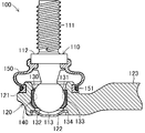
- FIG. 1 is a sectional view schematically showing a longitudinal section of a ball joint 100 including a ball seat 130 as a ball joint bearing seat according to the present invention. Note that each drawing referred to in the present specification is schematically represented by exaggerating some of the components in order to facilitate understanding of the present invention. For this reason, the dimension, ratio, etc. between each component may differ.
- the ball joint 100 is a joint member that connects components to each other while allowing a change in angle between the components in a suspension mechanism (suspension device) or a steering mechanism (steering device) employed in a vehicle such as an automobile. is there.
- the ball joint 100 shown in FIG. 1 shows one of the ball joints provided at both ends of a stabilizer link (not shown) in the suspension mechanism.
- the ball joint 100 is mainly configured by a ball stud 110, a housing 120, a ball seat 130, and a dust cover 150.
- the ball stud 110 is made of a steel material, and includes a ball portion 113 formed in a substantially spherical shape via a flange portion 112 on one end side of the shaft-shaped stud portion 111. Configured.
- the stud portion 111 is formed with a male screw for connecting the ball joint 100 to components in a steering mechanism (not shown).
- the housing 120 is formed by casting a material such as a non-ferrous metal or a steel material, and has a socket part 121 formed in a substantially cylindrical shape and a connecting part 123 formed extending in the horizontal direction from the socket part 121. It consists of and. In the present embodiment, the housing 120 is made of an aluminum alloy, but may be configured using other materials such as a magnesium material or a zinc material.
- the socket portion 121 is formed in a bottomed cylindrical shape in which one end portion (the upper end portion in the drawing) of the cylindrical body is opened and the other end portion (the lower end portion in the drawing) is closed by the plug 122.
- the inner peripheral part of the cylindrical body of the socket part 121 is a part that accommodates and holds the ball part 113 of the ball stud 110 via the ball seat 130.
- the plug 122 is a plate-like member for closing one end of the socket portion 121 formed in a cylindrical shape, and is configured by forming a steel material into a disc shape with a recessed central portion.
- one end (the left side in the figure) of the connecting part 123 is connected to the socket part 121 and the other end (the right side in the figure) is connected to an arm part (not shown) in the stabilizer link.
- a ball seat 130 as a bearing seat is provided on the inner peripheral portion of the socket portion 121 in the housing 120 between the ball portion 113 of the ball stud 110 held on the inner peripheral portion.
- the ball seat 130 is formed in a substantially cylindrical shape having an inner peripheral surface along the spherical surface of the ball portion 113 in the ball stud 110, and the ball portion 113 of the ball stud 110 is rotated and slid in the socket portion 121 of the housing 120. Hold in a state of being included freely.
- the ball sheet 130 is made of polyetheretherketone resin (PEEK), polymide resin (PI), polyacetal resin (POM), polyester resin (PVC), polyurethane. It is made of a synthetic resin material having heat resistance such as resin (PUR), polycarbonate resin (PC), polystyrene resin (PS), nylon resin (66N, UMC) or polypropylene (PP).
- the ball seat 130 there are a straight portion 133 extending linearly along the axial direction of the stud portion 111 of the ball stud 110, and a tapered portion 134 in which the lower side of the straight portion 133 is narrowed in the drawing. Is formed.
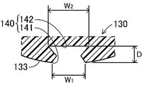
- an undercut portion 140 is formed on the straight portion 133.
- the undercut portion 140 is a portion for fixedly connecting the ball seat 130 to the housing 120, and is formed in a groove shape along the axial direction of the stud portion 111 of the ball stud 110.
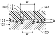
- the undercut portion 140 is formed such that the inner width W 2 of the bottom portion 142 is wider than the opening width W 1 of the opening portion 141 that opens to the outer peripheral surface of the ball sheet 130, and It is formed by a shallow depth D than the opening width W 1.
- the depth D of the undercut portion 140 is set to a depth at which the thickness of the thinnest portion (in the broken line circle in FIG. 1) of the outer peripheral portion of the undercut portion 140 remains 1/3 or more. ing. Twelve undercut portions 140 are formed on the outer peripheral surface of the ball sheet 130 at equal intervals.
- a dust cover 150 is provided on the upper part of the socket part 121 of the housing 120 so as to cover the upper part of the socket part 121 and the ball part 113 of the ball stud 110 accommodated in the socket 121 part.
- the dust cover 150 is made of an elastically deformable rubber material, a soft synthetic resin material, or the like, and is formed in a substantially cylindrical shape having a bulged central portion.
- the dust cover 150 has a stud portion 111 of the ball stud 110 inserted into one (upper side in the drawing) opening and is fixed to the lower portion of the stud portion 111 by an elastic force.
- the other opening (lower side in the figure) of the dust cover 150 is fixed by the fixing ring 151 in a state of being fitted into the upper portion of the outer peripheral portion of the socket portion 121. As a result, entry of foreign matter into the ball sheet 130 is prevented.
- the worker prepares a ball stud 110 and a ball seat 130 which are parts constituting the ball joint 100, respectively.
- an undercut portion 140 is formed on the outer peripheral surface of the ball sheet 130.
- the worker sets these parts in a mold (not shown) for molding the housing 120.
- the ball sheet 130 is set in the mold in a state in which the ball portion 113 of the ball stud 110 is held in the housing portion 131 so as to be able to rotate and slide.
- the operator casts an aluminum alloy into the mold in which the ball stud 110 and the ball sheet 130 are set (aluminum die casting).
- the housing 120 provided with the ball stud 110 and the ball seat 130 is integrally molded.
- the molten aluminum alloy that has reached the outer peripheral surface of the ball sheet 130 flows into the undercut portion 140.
- the undercut portion 140 because the depth D is formed shallower than the opening width W 1 of the opening 141, also the injection pressure of the aluminum alloy is lower than conventional is filled well molten metal.
- the ball sheet 130 heated by the molten aluminum alloy has a contraction rate different from that of the aluminum alloy, more specifically, a contraction rate larger than that of the aluminum alloy. Shrink with. For this reason, when the mold is cooled, a gap may be formed between the inner peripheral surface of the socket part 121 and the outer peripheral surface of the ball seat 130 in the housing 130. However, the ball seat 130 is firmly coupled to the inner peripheral surface of the socket portion 121 in the housing 130 by being caught in the solidified housing 130 by flowing into the undercut 140 when the opening 141 in the undercut 140 contracts. Is done.
- the operator prepares the plug 122 and the dust cover 150 and attaches them to the housing 120. Specifically, an operator sets the plug 122 in a jig (not shown) in a state where the plug 122 is arranged in the opening on the lower side of the housing 120 and crimps the opening to fix the plug 122. Further, the operator fits one end (the upper side in the figure) of the dust cover 150 into the outer periphery of the ball stud 110 and the other end (the lower side in the figure) of the dust cover 150 as the upper outer periphery of the housing 120. Fit into the part. Then, the operator fixes the dust cover 150 to the housing 120 by fitting the fixing ring 151 into the dust cover 150 fitted to the upper outer peripheral portion of the housing 120. Thereby, the ball joint 100 is completed.
- the ball joint 100 is incorporated in a suspension mechanism (suspension device) of a vehicle such as an automobile.
- the suspension mechanism is a device that maintains the running stability and steering stability of the vehicle by attenuating vibrations from the road surface and grounding the wheels to the road surface.
- the ball joint 100 supports the load from the vehicle while rotating or swinging the ball stud 110 in a certain direction in the suspension mechanism.
- the ball stud 110 swings in a certain direction in accordance with the vertical movement when the vehicle travels.
- the ball part 113 accommodated in the accommodation part 131 of the ball seat 130 rotates and slides in a certain direction corresponding to the swinging direction of the ball stud 110 in the accommodation part 131 of the ball sheet 130.
- the socket part 121 is not loosened or loosened.
- the fall of the rigidity of ball joint 100 is prevented.
- the undercut portion 140 of the ball sheet 130 is formed in parallel to the axial direction of the ball stud 110, the ball seat 130 and the ball stud 110 are prevented from being rotated around the axial line.
- the ball seat 130, the internal width of the bottom 142 to the opening width W 1 of the opening 141 on the outer peripheral surface in contact with the housing 120 W 2 is formed widely and is provided with a groove-like undercut portion 140 formed with a depth D shallower than the opening width W 1 of the opening 141. That is, the ball sheet 130 has a depth D that is excessively deep with respect to the opening width W 1 of the opening 141 because the depth D of the groove in the undercut portion 140 corresponds to the opening width W 1 of the opening 141 of the groove. Therefore, it is possible to prevent the poor hot water of the aluminum alloy due to the formation.
- the ball seat 140 can improve the coupling force with respect to the housing 120, and as a result, the rigidity required for the ball joint 100 can be easily ensured.
- the depth D of the grooves in the undercut portion 140 below the opening width W 1 of the opening 141 of the groove, accurately housing 120 by suppressing Tokoroiyu around bad It is confirmed that the ball sheet 130 can be coupled.
- 12 undercut portions 140 are arranged on the outer peripheral surface of the ball seat 130 at equal intervals.
- the number and positions of the undercut portions 140 are not limited to those in the first embodiment as long as the ball sheet 130 can be coupled to the housing 120.
- at least one undercut portion 140 may be provided on the outer peripheral surface of the ball sheet 130.
- at least three or more of the undercut portions 140 are arranged at equal intervals on the outer peripheral surface of the ball sheet 130, so that the ball sheet 130 can be balanced with the arrangement of the equal bonding force to the housing 120. Can be combined.
- the undercut portion 140 is continuously formed on the straight portion 133 on the outer peripheral surface of the ball sheet 130.
- the undercut part 140 should just be provided on the outer peripheral surface which contact
- FIG. therefore, for example, the undercut part 140 may be formed in the taper part 134 on the outer peripheral surface of the ball seat 130. According to this, since the taper portion 134 is a portion facing the portion that receives the axial load directly from the ball stud 110 in the housing portion 131 of the ball seat 130, the ball seat 130 is more firmly coupled to the housing 120. can do.
- the undercut portion 140 is formed on the outer peripheral surface of the ball sheet 130, it is not always necessary to form the undercut portion 140 continuously, and it may be formed intermittently on the outer peripheral surface of the ball sheet 130. According to this, the ball sheet 130 is formed so that the thickness of the portion where the undercut portion 140 is not formed is thicker than the thickness of the portion where the undercut portion 140 is formed. Can be improved.
- the undercut portion 140 is formed on the outer peripheral surface of the ball seat 130 in parallel with the axial direction of the ball stud 110.
- the undercut portion 140 is not necessarily limited to the first embodiment as long as it is formed on the outer peripheral surface of the ball sheet 130.
- the undercut portion 140 may be formed in a continuous or intermittent ring shape along the circumferential direction on the outer peripheral surface of the ball sheet 130.
- the undercut portion 140 may be formed by arranging a plurality of undercut portions 140 in parallel or in a staggered manner along the axial direction of the ball stud 110.
- An example in which the undercut portion 140 is formed along the circumferential direction on the outer peripheral surface of the ball sheet 130 will be described later as a second embodiment.
- the tip of the opening 141 of the undercut portion 140 is formed in a sharp shape.
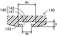
- the shape of the front end portion of the opening 141 of the undercut portion 140 is not limited to the first embodiment, and can be formed in a curved surface as shown in FIG. 4, for example. According to this, since the ball sheet 130 can increase the thickness of the tip of the opening 141 in the undercut portion 140, the ball sheet 130 disappears due to melting of the tip of the opening 141 when casting a molten aluminum alloy. Can be reduced. In FIG. 4, a cross-sectional view is intentionally shown to help understanding.
- the undercut portion 140 is formed in a weight shape that is inclined wide from the opening portion 141 toward both end portions of the bottom portion 142.
- the undercut portion 140 is shallower than the opening width W 1 of the opening 141 with an internal width W 2 of at least a portion of the bottom 142 side is formed wider to the opening width W 1 of the opening 141 As long as it is formed with the depth D, it is not necessarily limited to the first embodiment.
- the undercut part 140 can form the bottom part 142 side in the shape of a curved surface.
- the undercut portion 140 has a cross section wider than the opening width W 1 of the opening portion 141 at a portion on the bottom 142 side after passing through a predetermined thickness from the opening portion 141. It can also be formed so as to form a rectangular space.
- undercut portion 140 as shown in FIG. 7, after the width from both ends walls of the bottom 142 is inclined in the direction narrowed narrower than the opening width W 1, extends toward the opening 141 It can also be configured with an inclination. Also by these, the same effect as the first embodiment can be expected. 5 to 7 are shown in cross-sectional views in order to help understanding.
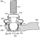
- FIG. 8 is a sectional view schematically showing a longitudinal section of a ball joint 200 including a ball seat 230 as a ball joint bearing seat according to the present invention.
- parts different from the first embodiment will be mainly described, and the same reference numerals (only the hundreds are changed) will be assigned to the same configuration as the first embodiment. The description including the operating part will be omitted as appropriate.
- the ball joint 200 according to the second embodiment is different from the ball joint 100 according to the first embodiment in that an undercut portion 240 formed in the ball seat 230 is different.
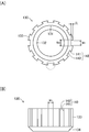
- the ball seat 230 in the second embodiment is formed in a substantially cylindrical shape having an inner peripheral surface along the spherical surface of the ball portion 213 in the ball stud 210, as shown in detail in FIGS. 9 (A) and 9 (B).
- the ball portion 213 of the ball stud 210 is held in the socket portion 221 of the housing 220 so as to be slidably slidable.
- the ball sheet 230 is made of the same resin material as the ball sheet 130 in the first embodiment, and is formed on the inner peripheral surface thereof in a spherical shape corresponding to the spherical surface of the ball portion 213 of the ball stud 210.
- the housing portion 231 and a hole 232 formed through the bottom of the housing portion 231 are formed.
- a straight portion 233 extending linearly along the axial direction of the stud portion 211 of the ball stud 210 is formed on the outer peripheral surface of the ball seat 230.
- the straight portion 233 is formed with an outer diameter reduced toward the lower side in the drawing in order to obtain a so-called draft at the time of casting.
- an undercut portion 240 is formed outside the hole portion 232 at the bottom end portion 235 that is the bottom end surface of the ball sheet 130 facing the lower plug 222 in the drawing.
- the undercut portion 240 is a portion for fixedly connecting the ball seat 230 in the housing 220, and is configured by a groove extending in a ring shape along the circumferential direction of the ball seat 230 formed of a cylindrical body. .
- the undercut portion 240 has a length corresponding to the opening width W 1 inside the undercut portion 240 than the opening width W 1 of the opening 241 formed by cutting a straight portion 233 at the outer undercut portion 240, i.e.
- the circumference is long (formed in a ring shape in the second embodiment), and is the distance from the opening width W 1 of the opening 241 to the bottom 242 that faces the opening 241.
- the depth D (in other words, the groove width of the undercut portion 240) is formed shallow.
- the depth D of the undercut portion 240 is a distance from the outer surface of the straight portion 233 where the opening portion 241 opens to the bottom portion 242 facing the opening portion 241 in the undercut portion 240.
- the groove width and the depth of the groove when the undercut portion 240 is viewed from the bottom end face are set within a range in which the rigidity of the housing portion 231 and the straight portion 233 can be secured.
- the undercut portion 240 is formed in a conical shape that is squeezed from the bottom end portion 235 side by extending along the housing portion 231 and the straight portion 233. Then, eight openings 241 constituting the undercut portion 240 are formed on the outer peripheral surface of the ball seat 230 at equal intervals.
- the worker forms a ball seat 230 that is a component constituting the ball joint.
- the operator forms the ball sheet 230 by resin injection molding using an injection molding machine (not shown).
- the ball sheet 230 since the ball sheet 230 is formed in the state opened at the bottom end 235 and along the circumferential direction of the ball sheet 230, the ball sheet 230 has an undercut portion 240 having an undercut shape through the opening 241.
- the ball sheet 230 can be easily injection molded.
- the worker prepares a ball stud 210 which is a component constituting the ball joint 200 in addition to the ball seat 230. Then, the operator sets the ball stud 210 and the ball seat 230 in a mold (not shown) for molding the housing 220, and casts the aluminum alloy into the mold (aluminum die casting) to mount the housing 220. Mold. Thereby, the housing 220 provided with the ball stud 210 and the ball seat 230 is integrally molded.
- the molten aluminum alloy that has reached the outer peripheral surface of the ball sheet 230, more specifically, the bottom end 235 flows into the undercut portion 240.
- the undercut portion 240 since the depth D with opened on the bottom side end portion 235 is formed shallower than the opening width W 1 of the opening 241, the injection pressure of the aluminum alloy conventionally Even if it is lower, the hot water is filled well.
- the ball sheet 230 heated by the molten aluminum alloy has a contraction rate different from that of the aluminum alloy, more specifically, larger than that of the aluminum alloy. Shrink at a shrinkage rate. For this reason, when the mold is cooled, a gap may be formed between the inner peripheral surface of the socket portion 221 and the outer peripheral surface of the ball seat 230 in the housing 220. However, when the opening 241 in the undercut 240 contracts, the ball seat 230 is firmly coupled to the inner peripheral surface of the socket portion 221 in the housing 220 by flowing into the undercut 240 and catching on the solidified housing 220. Is done.
- the operator After taking out the housing 220 integrally including the ball stud 210 and the ball seat 230 from the mold, the operator prepares the plug 222 and the dust cover 250 and attaches them to the housing 220 to attach the ball joint 200. To complete.
- the ball stud 210 swings in a certain direction in accordance with the vertical movement when the vehicle travels.
- the ball part 213 accommodated in the accommodating part 231 of the ball seat 230 is slid and rotated in a certain direction corresponding to the swinging direction of the ball stud 210 in the accommodating part 231 of the ball sheet 230.
- the socket part 221 is not loosened or loosened.
- the opening 241 in the undercut portion 240 is formed in parallel to the axial direction of the ball stud 210, the ball seat 230 is prevented from rotating around the axial line of the ball stud 210 together with the ball portion 213.
- the ball sheet 230 is in a state where the undercut portion 240 is opened at the bottom side end portion 235 of the ball sheet 230 formed of a cylindrical body.
- the ball sheet 230 is formed along the circumferential direction, it is easy to perform casting such as die casting of the ball sheet 230 having the undercut portion 240 having an undercut shape through the opening 241.
- the ball sheet 230 is formed by notching a part of the bottom end 235 on the side where the undercut portion 240 is formed in the ball sheet 230, the ball sheet 230 is cast. When molding the housing 220, hot water can be effectively guided into the undercut portion 240 through the opening 241.
- the ball seat 230 has eight openings 241 arranged evenly along the circumferential direction of the ball seat 230, the ball stud 210 can be connected to the housing 220 evenly in a well-balanced manner to hold the ball stud 210 for a long time. Can be held stably over the entire range. Further, the ball sheet 230 can improve the hot water flow into the undercut portion 240 when the housing 220 is formed by casting the ball sheet 230.
- openings 241 in the undercut portion 240 are arranged at equal intervals on the bottom end 235 in the ball seat 130.
- the number and positions of the openings 241 are not limited to those of the second embodiment as long as the ball seat 230 can be coupled to the housing 220.
- at least one opening 241 may be provided at the end of the ball sheet 230 on the side where the undercut portion 240 is formed.
- at least three or more of the ball sheets 230 are arranged at equal intervals at the end of the ball sheet 230 on the side where the undercut portions 240 are formed, so that the ball sheets 230 are evenly arranged with respect to the housing 220. Can be coupled in a well-balanced manner by arranging the appropriate coupling force.
- the undercut portion 240 is provided at the bottom end 235 of the ball sheet 230 made of a cylindrical body.
- the undercut part 240 should just be formed in the state opened to at least one of the both ends in the ball sheet 230 which consists of a cylinder, and along the circumferential direction of the ball sheet 230.
- FIG. therefore, for example, as shown in FIGS. 10A and 10B, the undercut portions 240 can be formed at both ends of a ball sheet 230 formed of a cylindrical body.
- the straight portion 233 is formed with an outer diameter expanding toward the upper side in the drawing in order to obtain a so-called draft at the time of casting.
- the undercut part 240 can also be provided only in the edge part by the side of the stud part 211 in the ball sheet 230 which consists of a cylinder.
- the undercut portion 240 is formed in a ring shape continuously connected on the bottom side end portion 235 of the ball seat 230.
- the undercut portion 240 can also be configured as an intermittent groove on the bottom side end portion 235 of the ball sheet 230.
- the opening 241 in the undercut portion 240 is configured to have a predetermined thickness from the outer surface of the straight portion 233.
- the opening 241 is not necessarily limited to the second embodiment as long as it communicates with the undercut portion 240.
- FIGS. 4, 5, and 7 in the first embodiment respectively. It is also possible to adopt a shape as shown.
- the ball joints 100 and 200 are employed in the steering mechanism.
- the ball joints 100 and 200 according to the present invention are not limited to this.
- the ball joints 100 and 200 can be widely applied to a suspension mechanism as well as a steering mechanism constituting a vehicle such as an automobile.
- W 1 ... opening width, W 2 ... internal width, D ... depth, 100 ... Ball joint, 110 ... ball stud, 111 ... stud part, 112 ... flange part, 113 ... ball part, 120 ... housing, 121 ... socket part, 122 ... plug, 123 ... connecting part, 130 ... Ball sheet 131 ... Accommodating part 132 ... Hole part 133 ... Straight part 134 ... Taper part 140 ... undercut part, 141 ... opening part, 142 ... bottom part, 150 ... dust cover, 151 ... fixing ring, 200 ... Ball joint, 210 ... Ball stud, 211 ... Stud part, 212 ... Flange part, 213 ... Ball part, 220 ...
- housing 221 ... socket part, 222 ... plug, 223 ... connecting part, 230 ... Ball sheet, 231 ... Housing part, 232 ... Hole part, 233 ... Straight part, 235 ... Bottom end part, 240 ... undercut part, 241 ... opening part, 242 ... bottom part, 250: dust cover, 251: fixing ring.
Landscapes
- Engineering & Computer Science (AREA)
- General Engineering & Computer Science (AREA)
- Mechanical Engineering (AREA)
- Physics & Mathematics (AREA)
- Geometry (AREA)
- Pivots And Pivotal Connections (AREA)
Priority Applications (2)
| Application Number | Priority Date | Filing Date | Title |
|---|---|---|---|
| JP2014504785A JP6150348B2 (ja) | 2012-03-14 | 2013-02-28 | ボールジョイント用ベアリングシートおよびボールジョイント |
| US14/383,932 US9546679B2 (en) | 2012-03-14 | 2013-02-28 | Bearing seat for a ball joint and a ball joint |
Applications Claiming Priority (2)
| Application Number | Priority Date | Filing Date | Title |
|---|---|---|---|
| JP2012058031 | 2012-03-14 | ||
| JP2012-058031 | 2012-03-14 |
Publications (1)
| Publication Number | Publication Date |
|---|---|
| WO2013137003A1 true WO2013137003A1 (fr) | 2013-09-19 |
Family
ID=49160919
Family Applications (1)
| Application Number | Title | Priority Date | Filing Date |
|---|---|---|---|
| PCT/JP2013/055430 Ceased WO2013137003A1 (fr) | 2012-03-14 | 2013-02-28 | Siège de roulement à rotule et roulement à rotule correspondant |
Country Status (3)
| Country | Link |
|---|---|
| US (1) | US9546679B2 (fr) |
| JP (1) | JP6150348B2 (fr) |
| WO (1) | WO2013137003A1 (fr) |
Cited By (2)
| Publication number | Priority date | Publication date | Assignee | Title |
|---|---|---|---|---|
| WO2017159458A1 (fr) * | 2016-03-14 | 2017-09-21 | 日本発條株式会社 | Joint à rotule et liaison de stabilisateur l'utilisant |
| KR20180110119A (ko) * | 2016-03-17 | 2018-10-08 | 니혼 하츠쵸 가부시키가이샤 | 볼 조인트 및 이것을 사용한 스태빌라이저 링크 |
Families Citing this family (8)
| Publication number | Priority date | Publication date | Assignee | Title |
|---|---|---|---|---|
| JP6253337B2 (ja) * | 2013-10-17 | 2017-12-27 | 株式会社ソミック石川 | ボールシートおよびボールジョイント |
| US10119562B2 (en) * | 2014-12-16 | 2018-11-06 | Itt Manufacturing Enterprises Llc | One-hand operable end fitting connector assembly |
| JP6016979B1 (ja) * | 2015-05-11 | 2016-10-26 | Thk株式会社 | ボールジョイントおよびボールジョイントの製造方法 |
| KR101815146B1 (ko) * | 2016-02-19 | 2018-03-15 | 주식회사 일진 | 볼 조인트 및 그 제작 방법 |
| DE102017108982B4 (de) * | 2017-04-26 | 2024-02-15 | Benteler Automobiltechnik Gmbh | Radlenker mit einem Kugelgelenk |
| KR101958433B1 (ko) | 2017-08-18 | 2019-03-20 | 주식회사 일진 | 볼 조인트 및 이를 포함하는 하이브리드 현가암 |
| US12560197B2 (en) | 2021-09-14 | 2026-02-24 | Tien-I Industrial Co., Ltd. | Universal joint |
| US20230078767A1 (en) * | 2021-09-14 | 2023-03-16 | Tien-I Industrial Co., Ltd. | Universal joint |
Citations (4)
| Publication number | Priority date | Publication date | Assignee | Title |
|---|---|---|---|---|
| JPS5719223U (fr) * | 1980-07-08 | 1982-02-01 | ||
| JP2005514242A (ja) * | 2002-01-17 | 2005-05-19 | ツェットエフ レムフェルダー メタルヴァーレン アクチエンゲゼルシャフト | プラスチックの一次成形の間の収縮特性を制御するための方法および装置 |
| JP2008511798A (ja) * | 2004-09-02 | 2008-04-17 | ツェットエフ フリードリヒスハーフェン アクチエンゲゼルシャフト | ボールジョイント |
| JP2011225065A (ja) * | 2010-04-17 | 2011-11-10 | Somic Ishikawa Inc | ボールジョイントおよびリンク部材 |
Family Cites Families (15)
| Publication number | Priority date | Publication date | Assignee | Title |
|---|---|---|---|---|
| JPS5719223A (en) | 1980-11-11 | 1982-02-01 | Kyoto Seisakusho:Kk | Accumulating method and apparatus for rod-formed articles |
| US4678472A (en) * | 1983-03-08 | 1987-07-07 | Joint Medical Products Corporation | Ball and socket bearing for artificial joint |
| DE3341255C1 (de) * | 1983-11-15 | 1985-06-13 | TRW Ehrenreich GmbH & Co KG, 4000 Düsseldorf | Kugelgelenk |
| JPS60237216A (ja) * | 1984-05-11 | 1985-11-26 | Toyota Motor Corp | ボ−ルジヨイント |
| DE3639962A1 (de) * | 1986-11-22 | 1988-06-01 | Trw Ehrenreich Gmbh | Kugelgelenk |
| FR2691415B1 (fr) * | 1992-05-25 | 1998-06-12 | Valeo Vision | Dispositif de montage du genre rotule et element intermediaire, notamment pour reflecteur de projecteur de vehicule automobile. |
| IT234539Y1 (it) * | 1994-05-20 | 2000-03-09 | Trafimet Spa | Torcia per saldatura a filo continuo con dispositivo di attacco del cavo a giunto sferico |
| US5772337A (en) * | 1997-05-01 | 1998-06-30 | Dana Corporation | Polywedge bearing for use with ball and socket |
| US6146045A (en) * | 1998-03-02 | 2000-11-14 | Dana Corporation | Triple seat non-articulating idler arm socket |
| US6164861A (en) * | 1998-03-13 | 2000-12-26 | Dana Corporation | Bearing set for a ball joint assembly |
| KR100272084B1 (ko) * | 1998-04-16 | 2000-11-15 | 강태릉 | 자동차용볼조인트 |
| US6952905B2 (en) * | 2003-02-03 | 2005-10-11 | Nickel Richard N | Stone panel connector |
| DE10328109B4 (de) * | 2003-06-20 | 2005-12-29 | ZF Lemförder Metallwaren AG | Kugelgelenk |
| US8123815B2 (en) * | 2008-11-24 | 2012-02-28 | Biomet Manufacturing Corp. | Multiple bearing acetabular prosthesis |
| US8870488B2 (en) * | 2009-06-19 | 2014-10-28 | Duracase Proprietary Llc | Joint assembly with reinforcing member and foam |
-
2013
- 2013-02-28 US US14/383,932 patent/US9546679B2/en not_active Expired - Fee Related
- 2013-02-28 JP JP2014504785A patent/JP6150348B2/ja active Active
- 2013-02-28 WO PCT/JP2013/055430 patent/WO2013137003A1/fr not_active Ceased
Patent Citations (4)
| Publication number | Priority date | Publication date | Assignee | Title |
|---|---|---|---|---|
| JPS5719223U (fr) * | 1980-07-08 | 1982-02-01 | ||
| JP2005514242A (ja) * | 2002-01-17 | 2005-05-19 | ツェットエフ レムフェルダー メタルヴァーレン アクチエンゲゼルシャフト | プラスチックの一次成形の間の収縮特性を制御するための方法および装置 |
| JP2008511798A (ja) * | 2004-09-02 | 2008-04-17 | ツェットエフ フリードリヒスハーフェン アクチエンゲゼルシャフト | ボールジョイント |
| JP2011225065A (ja) * | 2010-04-17 | 2011-11-10 | Somic Ishikawa Inc | ボールジョイントおよびリンク部材 |
Cited By (7)
| Publication number | Priority date | Publication date | Assignee | Title |
|---|---|---|---|---|
| WO2017159458A1 (fr) * | 2016-03-14 | 2017-09-21 | 日本発條株式会社 | Joint à rotule et liaison de stabilisateur l'utilisant |
| JP2017166524A (ja) * | 2016-03-14 | 2017-09-21 | 日本発條株式会社 | ボールジョイントおよびこれを用いたスタビリンク |
| KR20180107259A (ko) * | 2016-03-14 | 2018-10-01 | 니혼 하츠쵸 가부시키가이샤 | 볼 조인트 및 이것을 사용한 스태빌라이저 링크 |
| KR102129017B1 (ko) * | 2016-03-14 | 2020-07-02 | 니혼 하츠쵸 가부시키가이샤 | 볼 조인트 및 이것을 사용한 스태빌라이저 링크 |
| US11555516B2 (en) | 2016-03-14 | 2023-01-17 | Nhk Spring Co., Ltd. | Ball joint and stabilizer link using same |
| KR20180110119A (ko) * | 2016-03-17 | 2018-10-08 | 니혼 하츠쵸 가부시키가이샤 | 볼 조인트 및 이것을 사용한 스태빌라이저 링크 |
| KR102067684B1 (ko) | 2016-03-17 | 2020-01-20 | 니혼 하츠쵸 가부시키가이샤 | 볼 조인트 및 이것을 사용한 스태빌라이저 링크 |
Also Published As
| Publication number | Publication date |
|---|---|
| JPWO2013137003A1 (ja) | 2015-08-03 |
| JP6150348B2 (ja) | 2017-06-21 |
| US9546679B2 (en) | 2017-01-17 |
| US20150063899A1 (en) | 2015-03-05 |
Similar Documents
| Publication | Publication Date | Title |
|---|---|---|
| JP6150348B2 (ja) | ボールジョイント用ベアリングシートおよびボールジョイント | |
| JP5826508B2 (ja) | スタビリンクの製造方法 | |
| US10953577B2 (en) | Vehicular hybrid suspension arm and manufacturing method thereof | |
| US8061921B2 (en) | Insert-molded ball joint | |
| CA2816665C (fr) | Articulation stabilisatrice et procede de fabrication de cette articulation | |
| JP5721774B2 (ja) | ボールジョイント | |
| KR102067684B1 (ko) | 볼 조인트 및 이것을 사용한 스태빌라이저 링크 | |
| US20160252149A1 (en) | Axially Damping Elastomer Bearing, in particular for a Motor Vehicle | |
| JP5635271B2 (ja) | ボージョイント用ベアリングシートおよびボールジョイント | |
| JP2012143788A (ja) | 鋳造品 | |
| KR101573397B1 (ko) | 볼 조인트 어셈블리 및 그 제조방법 | |
| KR101814612B1 (ko) | 볼 조인트 및 그 제작 방법 | |
| JP6832206B2 (ja) | ボールジョイント、及びこれを用いたスタビリンク | |
| JP4812615B2 (ja) | ボールジョイント及びボールジョイントの製造方法 | |
| JP2011027237A (ja) | ボールジョイント用ベアリングシートにおける受け部および保持部の配置方法。 | |
| JP5132602B2 (ja) | ボールジョイントの製造方法 | |
| CN210509942U (zh) | 转向外拉杆球头总成和车辆 | |
| KR101242932B1 (ko) | 크로스 액시스 볼조인트 제조방법 | |
| JP5777466B2 (ja) | ボールジョイントの製造方法 | |
| JP2009299725A (ja) | ボールジョイントの製造方法 | |
| CN103785797A (zh) | 制造外管的方法和制造带轴承的外管的方法 | |
| JP7012345B2 (ja) | ボールジョイント及びその製造方法 | |
| JP7140368B2 (ja) | ボールジョイントのベアリングシート及びボールジョイント | |
| JP2010185521A (ja) | ベアリングシート、ボールジョイント、及び、ベアリングシートの製造方法 | |
| JP2008149333A (ja) | 部材接続方法、同方法により接続された複合部材 |
Legal Events
| Date | Code | Title | Description |
|---|---|---|---|
| 121 | Ep: the epo has been informed by wipo that ep was designated in this application |
Ref document number: 13760282 Country of ref document: EP Kind code of ref document: A1 |
|
| ENP | Entry into the national phase |
Ref document number: 2014504785 Country of ref document: JP Kind code of ref document: A |
|
| WWE | Wipo information: entry into national phase |
Ref document number: 14383932 Country of ref document: US |
|
| NENP | Non-entry into the national phase |
Ref country code: DE |
|
| 122 | Ep: pct application non-entry in european phase |
Ref document number: 13760282 Country of ref document: EP Kind code of ref document: A1 |