WO2013137190A1 - Système et procédé de gestion de charge, et dispositif monté sur un véhicule - Google Patents
Système et procédé de gestion de charge, et dispositif monté sur un véhicule Download PDFInfo
- Publication number
- WO2013137190A1 WO2013137190A1 PCT/JP2013/056629 JP2013056629W WO2013137190A1 WO 2013137190 A1 WO2013137190 A1 WO 2013137190A1 JP 2013056629 W JP2013056629 W JP 2013056629W WO 2013137190 A1 WO2013137190 A1 WO 2013137190A1
- Authority
- WO
- WIPO (PCT)
- Prior art keywords
- vehicle
- use reservation
- reservation
- parking
- time
- Prior art date
- Legal status (The legal status is an assumption and is not a legal conclusion. Google has not performed a legal analysis and makes no representation as to the accuracy of the status listed.)
- Ceased
Links
Images


Classifications
-
- B—PERFORMING OPERATIONS; TRANSPORTING
- B60—VEHICLES IN GENERAL
- B60L—PROPULSION OF ELECTRICALLY-PROPELLED VEHICLES; SUPPLYING ELECTRIC POWER FOR AUXILIARY EQUIPMENT OF ELECTRICALLY-PROPELLED VEHICLES; ELECTRODYNAMIC BRAKE SYSTEMS FOR VEHICLES IN GENERAL; MAGNETIC SUSPENSION OR LEVITATION FOR VEHICLES; MONITORING OPERATING VARIABLES OF ELECTRICALLY-PROPELLED VEHICLES; ELECTRIC SAFETY DEVICES FOR ELECTRICALLY-PROPELLED VEHICLES
- B60L58/00—Methods or circuit arrangements for monitoring or controlling batteries or fuel cells, specially adapted for electric vehicles
- B60L58/10—Methods or circuit arrangements for monitoring or controlling batteries or fuel cells, specially adapted for electric vehicles for monitoring or controlling batteries
- B60L58/12—Methods or circuit arrangements for monitoring or controlling batteries or fuel cells, specially adapted for electric vehicles for monitoring or controlling batteries responding to state of charge [SoC]
-
- B—PERFORMING OPERATIONS; TRANSPORTING
- B60—VEHICLES IN GENERAL
- B60L—PROPULSION OF ELECTRICALLY-PROPELLED VEHICLES; SUPPLYING ELECTRIC POWER FOR AUXILIARY EQUIPMENT OF ELECTRICALLY-PROPELLED VEHICLES; ELECTRODYNAMIC BRAKE SYSTEMS FOR VEHICLES IN GENERAL; MAGNETIC SUSPENSION OR LEVITATION FOR VEHICLES; MONITORING OPERATING VARIABLES OF ELECTRICALLY-PROPELLED VEHICLES; ELECTRIC SAFETY DEVICES FOR ELECTRICALLY-PROPELLED VEHICLES
- B60L53/00—Methods of charging batteries, specially adapted for electric vehicles; Charging stations or on-board charging equipment therefor; Exchange of energy storage elements in electric vehicles
- B60L53/30—Constructional details of charging stations
- B60L53/305—Communication interfaces
-
- B—PERFORMING OPERATIONS; TRANSPORTING
- B60—VEHICLES IN GENERAL
- B60L—PROPULSION OF ELECTRICALLY-PROPELLED VEHICLES; SUPPLYING ELECTRIC POWER FOR AUXILIARY EQUIPMENT OF ELECTRICALLY-PROPELLED VEHICLES; ELECTRODYNAMIC BRAKE SYSTEMS FOR VEHICLES IN GENERAL; MAGNETIC SUSPENSION OR LEVITATION FOR VEHICLES; MONITORING OPERATING VARIABLES OF ELECTRICALLY-PROPELLED VEHICLES; ELECTRIC SAFETY DEVICES FOR ELECTRICALLY-PROPELLED VEHICLES
- B60L53/00—Methods of charging batteries, specially adapted for electric vehicles; Charging stations or on-board charging equipment therefor; Exchange of energy storage elements in electric vehicles
- B60L53/60—Monitoring or controlling charging stations
- B60L53/68—Off-site monitoring or control, e.g. remote control
-
- B—PERFORMING OPERATIONS; TRANSPORTING
- B60—VEHICLES IN GENERAL
- B60L—PROPULSION OF ELECTRICALLY-PROPELLED VEHICLES; SUPPLYING ELECTRIC POWER FOR AUXILIARY EQUIPMENT OF ELECTRICALLY-PROPELLED VEHICLES; ELECTRODYNAMIC BRAKE SYSTEMS FOR VEHICLES IN GENERAL; MAGNETIC SUSPENSION OR LEVITATION FOR VEHICLES; MONITORING OPERATING VARIABLES OF ELECTRICALLY-PROPELLED VEHICLES; ELECTRIC SAFETY DEVICES FOR ELECTRICALLY-PROPELLED VEHICLES
- B60L2240/00—Control parameters of input or output; Target parameters
- B60L2240/70—Interactions with external data bases, e.g. traffic centres
-
- B—PERFORMING OPERATIONS; TRANSPORTING
- B60—VEHICLES IN GENERAL
- B60L—PROPULSION OF ELECTRICALLY-PROPELLED VEHICLES; SUPPLYING ELECTRIC POWER FOR AUXILIARY EQUIPMENT OF ELECTRICALLY-PROPELLED VEHICLES; ELECTRODYNAMIC BRAKE SYSTEMS FOR VEHICLES IN GENERAL; MAGNETIC SUSPENSION OR LEVITATION FOR VEHICLES; MONITORING OPERATING VARIABLES OF ELECTRICALLY-PROPELLED VEHICLES; ELECTRIC SAFETY DEVICES FOR ELECTRICALLY-PROPELLED VEHICLES
- B60L2260/00—Operating Modes
- B60L2260/40—Control modes
- B60L2260/50—Control modes by future state prediction
- B60L2260/54—Energy consumption estimation
-
- B—PERFORMING OPERATIONS; TRANSPORTING
- B60—VEHICLES IN GENERAL
- B60L—PROPULSION OF ELECTRICALLY-PROPELLED VEHICLES; SUPPLYING ELECTRIC POWER FOR AUXILIARY EQUIPMENT OF ELECTRICALLY-PROPELLED VEHICLES; ELECTRODYNAMIC BRAKE SYSTEMS FOR VEHICLES IN GENERAL; MAGNETIC SUSPENSION OR LEVITATION FOR VEHICLES; MONITORING OPERATING VARIABLES OF ELECTRICALLY-PROPELLED VEHICLES; ELECTRIC SAFETY DEVICES FOR ELECTRICALLY-PROPELLED VEHICLES
- B60L2260/00—Operating Modes
- B60L2260/40—Control modes
- B60L2260/50—Control modes by future state prediction
- B60L2260/58—Departure time prediction
-
- Y—GENERAL TAGGING OF NEW TECHNOLOGICAL DEVELOPMENTS; GENERAL TAGGING OF CROSS-SECTIONAL TECHNOLOGIES SPANNING OVER SEVERAL SECTIONS OF THE IPC; TECHNICAL SUBJECTS COVERED BY FORMER USPC CROSS-REFERENCE ART COLLECTIONS [XRACs] AND DIGESTS
- Y02—TECHNOLOGIES OR APPLICATIONS FOR MITIGATION OR ADAPTATION AGAINST CLIMATE CHANGE
- Y02T—CLIMATE CHANGE MITIGATION TECHNOLOGIES RELATED TO TRANSPORTATION
- Y02T10/00—Road transport of goods or passengers
- Y02T10/60—Other road transportation technologies with climate change mitigation effect
- Y02T10/70—Energy storage systems for electromobility, e.g. batteries
-
- Y—GENERAL TAGGING OF NEW TECHNOLOGICAL DEVELOPMENTS; GENERAL TAGGING OF CROSS-SECTIONAL TECHNOLOGIES SPANNING OVER SEVERAL SECTIONS OF THE IPC; TECHNICAL SUBJECTS COVERED BY FORMER USPC CROSS-REFERENCE ART COLLECTIONS [XRACs] AND DIGESTS
- Y02—TECHNOLOGIES OR APPLICATIONS FOR MITIGATION OR ADAPTATION AGAINST CLIMATE CHANGE
- Y02T—CLIMATE CHANGE MITIGATION TECHNOLOGIES RELATED TO TRANSPORTATION
- Y02T10/00—Road transport of goods or passengers
- Y02T10/60—Other road transportation technologies with climate change mitigation effect
- Y02T10/7072—Electromobility specific charging systems or methods for batteries, ultracapacitors, supercapacitors or double-layer capacitors
-
- Y—GENERAL TAGGING OF NEW TECHNOLOGICAL DEVELOPMENTS; GENERAL TAGGING OF CROSS-SECTIONAL TECHNOLOGIES SPANNING OVER SEVERAL SECTIONS OF THE IPC; TECHNICAL SUBJECTS COVERED BY FORMER USPC CROSS-REFERENCE ART COLLECTIONS [XRACs] AND DIGESTS
- Y02—TECHNOLOGIES OR APPLICATIONS FOR MITIGATION OR ADAPTATION AGAINST CLIMATE CHANGE
- Y02T—CLIMATE CHANGE MITIGATION TECHNOLOGIES RELATED TO TRANSPORTATION
- Y02T10/00—Road transport of goods or passengers
- Y02T10/60—Other road transportation technologies with climate change mitigation effect
- Y02T10/72—Electric energy management in electromobility
-
- Y—GENERAL TAGGING OF NEW TECHNOLOGICAL DEVELOPMENTS; GENERAL TAGGING OF CROSS-SECTIONAL TECHNOLOGIES SPANNING OVER SEVERAL SECTIONS OF THE IPC; TECHNICAL SUBJECTS COVERED BY FORMER USPC CROSS-REFERENCE ART COLLECTIONS [XRACs] AND DIGESTS
- Y02—TECHNOLOGIES OR APPLICATIONS FOR MITIGATION OR ADAPTATION AGAINST CLIMATE CHANGE
- Y02T—CLIMATE CHANGE MITIGATION TECHNOLOGIES RELATED TO TRANSPORTATION
- Y02T90/00—Enabling technologies or technologies with a potential or indirect contribution to GHG emissions mitigation
- Y02T90/10—Technologies relating to charging of electric vehicles
- Y02T90/12—Electric charging stations
-
- Y—GENERAL TAGGING OF NEW TECHNOLOGICAL DEVELOPMENTS; GENERAL TAGGING OF CROSS-SECTIONAL TECHNOLOGIES SPANNING OVER SEVERAL SECTIONS OF THE IPC; TECHNICAL SUBJECTS COVERED BY FORMER USPC CROSS-REFERENCE ART COLLECTIONS [XRACs] AND DIGESTS
- Y02—TECHNOLOGIES OR APPLICATIONS FOR MITIGATION OR ADAPTATION AGAINST CLIMATE CHANGE
- Y02T—CLIMATE CHANGE MITIGATION TECHNOLOGIES RELATED TO TRANSPORTATION
- Y02T90/00—Enabling technologies or technologies with a potential or indirect contribution to GHG emissions mitigation
- Y02T90/10—Technologies relating to charging of electric vehicles
- Y02T90/16—Information or communication technologies improving the operation of electric vehicles
- Y02T90/167—Systems integrating technologies related to power network operation and communication or information technologies for supporting the interoperability of electric or hybrid vehicles, i.e. smartgrids as interface for battery charging of electric vehicles [EV] or hybrid vehicles [HEV]
-
- Y—GENERAL TAGGING OF NEW TECHNOLOGICAL DEVELOPMENTS; GENERAL TAGGING OF CROSS-SECTIONAL TECHNOLOGIES SPANNING OVER SEVERAL SECTIONS OF THE IPC; TECHNICAL SUBJECTS COVERED BY FORMER USPC CROSS-REFERENCE ART COLLECTIONS [XRACs] AND DIGESTS
- Y04—INFORMATION OR COMMUNICATION TECHNOLOGIES HAVING AN IMPACT ON OTHER TECHNOLOGY AREAS
- Y04S—SYSTEMS INTEGRATING TECHNOLOGIES RELATED TO POWER NETWORK OPERATION, COMMUNICATION OR INFORMATION TECHNOLOGIES FOR IMPROVING THE ELECTRICAL POWER GENERATION, TRANSMISSION, DISTRIBUTION, MANAGEMENT OR USAGE, i.e. SMART GRIDS
- Y04S30/00—Systems supporting specific end-user applications in the sector of transportation
- Y04S30/10—Systems supporting the interoperability of electric or hybrid vehicles
- Y04S30/12—Remote or cooperative charging
Definitions
- the present invention relates to a charge management system that manages charging of a vehicle, a charge management method, and an in-vehicle device.
- Patent Document 1 a charging device for an electric vehicle that reliably charges a shared vehicle is known.
- Patent Document 1 describes that even when a vehicle is present and the vehicle is not connected to a charging device even during a predetermined charging time period, a warning is issued to prevent forgetting to charge.
- the present invention has been proposed in view of the above-described circumstances, and an object thereof is to provide a charge management system, a charge management method, and an in-vehicle device that can suppress insufficient charging of a vehicle.
- a charge management system, a charge management method, and an in-vehicle device store a scheduled use start time of a vehicle, a scheduled use end time, a use reservation in which a destination is set, and a chargeable time of the vehicle. Then, it is determined whether or not the amount of power for the first use reservation is insufficient. When the amount of power of the first use reservation is insufficient, information recommending charging of the in-vehicle battery is presented during a period in which the vehicle is used by the second use reservation prior to the first use reservation.
- FIG. 1 is a block diagram of a charge management system shown as the present embodiment.
- FIG. 2 is a flowchart showing an operation in the charge management system shown as the present embodiment.
- FIG. 3 is a flowchart showing an example of parking detection processing in the charge management system shown as the present embodiment.
- FIG. 4 is a flowchart showing another example of the parking detection process in the charge management system shown as the present embodiment.
- FIG. 5 is a flowchart showing another example of the parking detection process in the charge management system shown as the present embodiment.
- FIG. 6 is a flowchart showing another example of the parking detection process in the charge management system shown as the present embodiment.
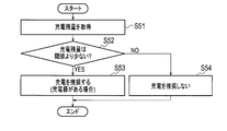
- FIG. 7 is a flowchart showing an example of a determination process of whether or not charging is necessary in the charge management system shown as the present embodiment.
- FIG. 1 is a block diagram of a charge management system shown as the present embodiment.
- FIG. 2 is a flowchart showing an operation in the charge management system shown as the present embodiment.
- FIG. 3 is
- FIG. 8 is a flowchart showing another example of the determination process of whether or not charging is necessary in the charge management system shown as the present embodiment.
- FIG. 9 is a diagram for explaining the operation of the charge management system shown as the present embodiment, where (a) shows the transition of the remaining charge of the comparative example, and (b) shows the transition of the remaining charge of the present embodiment.
- Show. 10A and 10B are diagrams for explaining the operation of the charge management system shown as the present embodiment.
- FIG. 10A shows a scene where charging is not recommended
- FIG. 10B shows a scene where charging is recommended.
- FIG. 10A shows a scene where charging is not recommended.
- FIG. 11 is a diagram illustrating that in the charge management system shown as the present embodiment, information that recommends charging when parking for a long time is presented, and information that recommends charging is not presented when charging with an insufficient amount of power is completed. It is.
- FIG. 12 is another diagram showing that in the charge management system shown as the present embodiment, information that recommends charging when parking for a long stay time is presented and information that recommends charging is not presented when parking for a short stay time. is there.
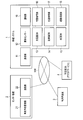
- the charge management system shown as an embodiment of the present invention is configured as shown in FIG.
- This charge management system manages charging of a vehicle so that a plurality of users can use the vehicle jointly.
- This charging management system is configured by connecting a vehicle-mounted system (vehicle-mounted device) 1, a center device 2, a user terminal 3, and a schedule table database 4 to a network NW.
- the vehicle in this charge management system is an electric vehicle (EV).
- EV electric vehicle
- a destination such as a destination is set for this electric vehicle when a user makes a reservation for use.
- This electric vehicle is connected to a return (return) port provided in a predetermined parking area.
- This return port is a charging station for an electric vehicle. The electric vehicle is removed from the return port when the vehicle is rented, and is connected to the return port when the vehicle is returned.
- the user terminal 3 is a personal computer, a mobile terminal, a mobile phone or the like.
- the user terminal 3 is connected to the center device 2 and the schedule table database 4 via a network NW such as the Internet.
- NW such as the Internet.
- the user terminal 3 displays a reservation screen on a display (not shown) according to the control of the center device 2.
- the user terminal 3 accepts various types of information according to user operations.
- the user terminal 3 receives a user ID, a desired vehicle type, a destination, a scheduled use start date / time (scheduled use start time), and a scheduled use end date / time (scheduled use end time).
- the user terminal 3 transmits the user ID, the desired vehicle type, the destination, the scheduled use start date and time, and the scheduled use end date and time to the center device 2 together with the electric vehicle use request. Moreover, the staying time in the destination may be set to the use reservation.
- the center device 2 manages use reservations by a plurality of users for a plurality of electric vehicles.
- Center device 2 includes a vehicle reservation management unit 21 and a communication unit 22.
- the vehicle reservation management unit 21 is actually composed of a ROM, a RAM, a CPU, and the like, but functions that can be realized by the CPU performing processing according to a charge management program stored in the ROM will be described as blocks. To do.
- the communication unit 22 is a communication interface or the like that can communicate via the network NW.
- the vehicle reservation management unit 21 transmits usage reservation information in which a user ID, a desired vehicle type, a destination, a scheduled usage start date and time, and a scheduled usage end date and time are set together with a request for using an electric vehicle from the user terminal 3. .
- the center device 2 determines whether or not there is an electric vehicle that meets the use conditions of the destination related to the use request, the scheduled use start date and time, and the scheduled use end date and time. When there is an electric vehicle that meets the usage conditions, the usage reservation is registered by storing the usage reservation. Thereby, in the center apparatus 2, a schedule including a plurality of use reservations arranged in time series is constructed for each vehicle.
- the center device 2 stores a scheduled use start time, a scheduled use end time, a use reservation in which a destination is set, and a vehicle chargeable time.
- the chargeable time of the electric vehicle is a period during which the electric vehicle is connected to the charger of the return port between use reservations that change in time. This chargeable time is approximately the value obtained by multiplying the chargeable amount per unit time by the period between the scheduled use end date and time set in the previous use reservation and the scheduled use start date and time set in the subsequent use reservation. It is.
- the center device 2 calculates the amount of power for recommending charging of the on-vehicle battery. Based on the expected power consumption based on the destination set in the first (rear) use reservation and the chargeable time until the scheduled use start time set in the first use reservation, the center device 2 It is determined whether or not the amount of power for the first use reservation is insufficient. Further, the center device 2 is based on the estimated power consumption based on the destination set in the first (rear) use reservation and the chargeable time until the scheduled use start time set in the first use reservation. Then, the insufficient power amount of the first use reservation is calculated. This insufficient power amount is transmitted to the in-vehicle system 1 and stored by the scheduled use start date and time in the second use reservation before the first use reservation. Further, the insufficient power amount may be transmitted to the schedule table database 4 and stored as a recommended charge amount in the second (previous) use reservation.
- the schedule table database 4 is constructed by a cloud service in which a user uses computer processing as a service via a network.
- the schedule table database 4 stores a schedule table constructed by the center device 2.
- the schedule database 4 transmits the schedule to the requesting device in response to a request from the center device 2, the user terminal 3, or the in-vehicle system 1. Further, the schedule table database 4 may store a recommended charge amount corresponding to the insufficient power amount calculated by the center device 2 for each use reservation.
- the in-vehicle system 1 is in a period when the vehicle is used by the second (rear) use reservation in which the planned use end time is set before the planned use start time set in the first (rear) use reservation. Presents information that recommends charging the vehicle battery. Moreover, the vehicle-mounted system 1 may present the information recommending charging the insufficient electric energy of a vehicle-mounted battery.
- the in-vehicle system 1 includes a communication unit 11, a vehicle sensor 12, a charger database 13, a parking lot database 14, a map database 15, a position acquisition unit 16, a position search unit 17, a route search unit 18, and a notification unit 19.
- the communication unit 11 includes a communication interface that communicates with the center device 2 and the schedule table database 4 via the network NW.
- the vehicle sensor 12 detects the remaining charge amount of the in-vehicle battery mounted on the electric vehicle.
- the charger database 13 stores latitude and longitude information where a charger capable of charging an electric vehicle is installed.
- the parking lot database 14 stores latitude and longitude information of parking lots where electric vehicles can be parked.
- the map database 15 stores road link information indicating a road on which an electric vehicle can travel, road node information indicating an intersection, facility information indicating a type of a point, and the like.
- the charger database 13, the parking lot database 14, and the map database 15 are stored in a server (not shown) connected to the in-vehicle system 1 via the network NW if the in-vehicle system 1 is accessible. It may be.
- the position acquisition unit 16 includes, for example, a GPS receiver and the like, calculates current position information, and further acquires current time information.
- the position search unit 17 receives a user operation and detects a position corresponding to the operation.
- the position search unit 17 refers to the map database 15 and searches for the position of the destination of the electric vehicle.
- the position search unit 17 refers to the parking lot database 14 and searches for a position of the parking lot close to the current position information of the electric vehicle.
- the route search unit 18 receives a destination setting operation by the user, and refers to the map database 15 to search for a recommended route from the current position of the electric vehicle to the destination.
- the notification unit 19 includes a display that presents various information, a speaker, and the like.
- the notification unit 19 presents information that recommends charging the in-vehicle battery for a subsequent use reservation subsequent to the current use (presentation means).
- the notification unit 19 also provides insufficient power for the subsequent use reservation.
- Information that recommends charging the amount can also be presented (presentation means).
- the in-vehicle system 1 may store a use reservation (storage means), as with the center device 2. Furthermore, the in-vehicle system 1, similarly to the center device 2, expects power consumption based on the destination set in the first (rear) use reservation and the scheduled use start time set in the first use reservation. It may be determined whether or not the amount of power required for the first use reservation is insufficient based on the available charging time. Furthermore, the in-vehicle system 1 may calculate an insufficient power amount of the first usage reservation (calculation means).
- reservation information is transmitted from the center device 2 via the network NW.
- This reservation information includes a user ID, a scheduled use start date and time, and a scheduled use end date and time.
- the user of the electric vehicle places the IC card on an IC card reader (not shown) mounted on the vehicle after the scheduled use start date and time.
- the IC card reader reads the user ID stored in the IC card, and when it matches the user ID included in the reservation information, controls the key device to open the key.
- the in-vehicle system 1 is connected (returned) to the port (return position) by the scheduled end date of use of the electric vehicle. After the use is completed, the IC card is put on the IC card reader. The in-vehicle system 1 recognizes that the electric vehicle has been returned to the port from the current position information, and notifies the center device 2 that it has been returned.
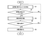
- step S1 the in-vehicle system 1 detects whether the electric vehicle is about to stop to park in the parking lot.
- the details of the electric vehicle parking detection process will be described later with reference to FIGS.
- step S2 the in-vehicle system 1 determines whether or not the electric vehicle is about to stop at the parking lot based on the result of the parking detection process in step S1. If the electric vehicle is about to stop at the parking lot, the process proceeds to step S3. If not, the process returns to step S1.
- step S3 the in-vehicle system 1 determines whether charging by an electric vehicle is necessary. The details of the determination process of whether or not charging is necessary will be described later with reference to FIGS.
- step S4 the in-vehicle system 1 determines whether or not the electric vehicle needs to be charged based on the result of the determination process of whether or not charging is required in step S3. If the electric vehicle needs to be charged, the process proceeds to step S5, and if not, the process returns to step S1.
- step S5 the in-vehicle system 1 uses the notification unit 19 to present information that recommends charging to the user of the electric vehicle.
- you may show required recommended charge amount to the information which recommends this charge.
- the vehicle-mounted system 1 may present the information which recommends charge, for example, when the parking brake which stops an electric vehicle is operated.
- the presentation method may be displayed on a vehicle-mounted display, or sound may be output from a speaker.
- step S1 the parking detection process in step S1 described above will be described.
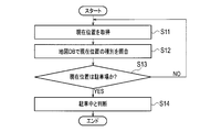
- step S11 the position acquisition unit 16 acquires current position information of the electric vehicle.
- the position search unit 17 of the in-vehicle system 1 refers to the map database 15 and collates the type of the current position acquired in step S11. This type is information such as a parking lot.
- step S13 the in-vehicle system 1 determines whether or not the type of the current position is a parking lot as a result of the process in step S12. If the type of the current position is a parking lot, the process proceeds to step S14; otherwise, the process returns to step S11.
- step S14 the in-vehicle system 1 determines that the electric vehicle is currently parked in the parking lot.
- step S ⁇ b> 21 the in-vehicle system 1 determines whether or not a destination for route search is input by the route search unit 18. At this time, the in-vehicle system 1 determines whether or not the destination information is stored by the route search unit 18. If it is determined that the destination has been input, the process proceeds to step S22. If not, the process ends.
- step S ⁇ b> 22 the in-vehicle system 1 acquires the current position information of the electric vehicle by the position acquisition unit 16.
- step S23 the in-vehicle system 1 determines whether or not the current position acquired in step S22 by the position search unit 17 is around the destination determined to have been input in step S21. For example, the position search unit 17 determines that the electric vehicle is located around the destination when the current position is within a range of several tens of meters from the destination. Further, the position search unit 17 may determine that the current position of the electric vehicle is around the destination that the electric vehicle is traveling toward the destination. If it is determined that the current position of the electric vehicle is around the destination, the process proceeds to step S24, and if not, the process ends.
- step S24 the in-vehicle system 1 determines that the electric vehicle is parked after arrival at the destination.
- this in-vehicle system when it is detected that the acquired current position is around the destination set in the use reservation, parking of the vehicle is detected. Thereby, according to the in-vehicle system 1, it is possible to recommend charging of the in-vehicle battery to the user only when the electric vehicle is parked. When charging is necessary, for example, frequent recommendation of charging during traveling can be suppressed.
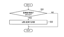
- the parking detection process shown in FIG. 5 first determines in step S31 whether or not the parking lot has been searched by the route search unit 18 of the in-vehicle system 1. At this time, the in-vehicle system 1 accepts a user's operation such as a button, and determines whether or not a parking lot has been searched as a peripheral facility. If it is determined that a parking lot has been searched, the process proceeds to step S32. If not, the process ends.
- step S32 the in-vehicle system 1 determines that the electric vehicle is parked after that because the user is about to park the electric vehicle in the parking lot.
- the in-vehicle system when an operation for searching for a parking lot by a user is detected, parking of the vehicle is detected. Thereby, according to the vehicle-mounted system 1, charging can be recommended to the user only when the electric vehicle is parked. When charging is necessary, for example, frequent recommendation of charging during traveling can be suppressed.
- the parking detection process shown in FIG. 6 first accesses the schedule table database 4 by the communication unit 11 of the in-vehicle system 1 in step S41. At this time, the in-vehicle system 1 transmits a schedule download request including the ID of the electric vehicle, the user ID, and the like to the schedule table database 4.
- step S42 the in-vehicle system 1 acquires from the schedule table database 4 a schedule table that matches the electric vehicle ID and user ID.
- the in-vehicle system 1 determines whether or not the current destination has been acquired from the use reservation included in the acquired schedule. If it is determined that the current destination has been acquired, the process proceeds to step S43. If not, the process ends.
- step S43 the position acquisition unit 16 of the in-vehicle system 1 acquires current position information of the electric vehicle.
- the in-vehicle system 1 determines whether or not the current position acquired in step S43 by the position search unit 17 is near the destination acquired in step S42. For example, the position search unit 17 determines that the electric vehicle is located near the destination when the current position is within a range of several tens of meters from the destination. Further, the position search unit 17 may determine that there is a high possibility of arrival at the destination at the scheduled time as scheduled. If it is determined that the current position of the electric vehicle is near the destination, the process proceeds to step S45, and if not, the process returns to step S43.
- step S45 the in-vehicle system 1 determines that the electric vehicle is parked after arrival at the destination. In addition, the in-vehicle system 1 determines that parking is performed thereafter when the scheduled time approaches the scheduled time.
- this in-vehicle system when it is detected that the acquired current position is around the destination set in the use reservation, parking of the vehicle is detected. Thereby, according to the vehicle-mounted system 1, charging can be recommended to the user only when the electric vehicle is parked. When charging is necessary, for example, frequent recommendation of charging during traveling can be suppressed.
- step S3 the process for determining whether or not charging is necessary in step S3 will be described.
- step S51 the vehicle sensor 12 of the in-vehicle system 1 acquires the remaining charge amount of the in-vehicle battery.
- the in-vehicle system 1 determines whether or not the remaining charge amount of the in-vehicle battery acquired in step S51 is less than a threshold value.
- This threshold value may be a preset value (for example, SOC is 20%), and varies based on the distance from the current position of the electric vehicle to the destination or the distance from the current position of the electric vehicle to the return position. You may let them. If it is determined that the remaining charge is less than the threshold, the process proceeds to step S53, and if not, the process proceeds to step S54.
- step S53 the in-vehicle system 1 presents information recommending charging of the electric vehicle to the user by the notification unit 19.
- the in-vehicle system 1 does not recommend charging by the notification unit 19.
- this charge management system it is possible to present information that recommends charging of an electric vehicle when the remaining charge of the on-vehicle battery is low, and it is necessary without frequently bothering because charging is recommended frequently. Charging can be recommended depending on Although it is possible to tell to always charge when parking is detected, the in-vehicle system 1 can suppress the recommended number of times.
- the determination process for determining whether charging is necessary presents information that recommends charging when there is a charger around the position to be parked obtained by the parking detection process.
- the in-vehicle system 1 acquires the current position of the electric vehicle by the position acquisition unit 16 and refers to the charger database 13 in which the position of the charger is stored. Then, when the current position of the electric vehicle is around the charger stored in the charger database 13, information recommending charging of the in-vehicle battery or information recommending charging the insufficient power amount of the subsequent use reservation is provided. Present. Thereby, according to this in-vehicle system 1, it is necessary to detect the parking of the electric vehicle, and the electric vehicle needs to be charged.
- the charging can be recommended, and the vehicle is moved to the charger for parking. Can be made.
- the vehicle-mounted system 1 may change the parking position of the electric vehicle to a position where the charger exists by the route search unit 18. For example, when there is a charger on the third floor of the multilevel parking lot, information such as “Please connect to the charger on the third floor” can be included in the information that recommends charging.
- step S61 the vehicle sensor 12 of the in-vehicle system 1 acquires the remaining charge P1 of the in-vehicle battery.
- the in-vehicle system 1 determines whether or not the amount of power necessary for the first (rear) use reservation is insufficient. In the next step S62, the in-vehicle system 1 estimates the power consumption P2 that the electric vehicle consumes to travel to the return port. At this time, the in-vehicle system 1 estimates the power consumption P2 based on the distance from the current position to the destination, the average travel speed, the power consumption per unit distance, and the like.
- the in-vehicle system 1 estimates the chargeable power amount P3 that can be charged from the scheduled use end date / time in the current use reservation to the scheduled use start date / time in the next use reservation.
- This chargeable power amount P3 is calculated by calculating the amount of charge per unit time of the charger from the scheduled use end date / time in the current use reservation to the scheduled use start date / time in the next use reservation. Estimate by multiplying.
- the in-vehicle system 1 calculates an expected power consumption P4 consumed by the next use reservation. At this time, the in-vehicle system 1 calculates the predicted power consumption P4 based on the destination information set for the next use reservation. For example, the predicted power consumption P4 is calculated based on the moving distance according to the position of the return port or the destination and the power consumption per unit distance.
- the in-vehicle system 1 determines whether or not the insufficient power amount obtained by subtracting the power consumption amount P2 and the chargeable power amount P3 from the remaining charge amount P1 acquired in step S61 is equal to or less than the predicted power consumption amount P4. Determine whether. This insufficient power amount is a shortage of the power amount necessary for the next use reservation. If it is determined that the insufficient power amount is equal to or less than the predicted power consumption P4, the process proceeds to step S66, and if not, the process returns to step S67.
- step S66 the in-vehicle system 1 presents information recommending charging of the electric vehicle to the user by the notification unit 19.
- the in-vehicle system 1 charges the in-vehicle battery during a period in which the vehicle is used by the current use reservation in which the scheduled use end time is set before the scheduled use start time set in the subsequent use reservation.
- Information recommending charging, or information recommending charging the amount of insufficient power can be presented.
- step S ⁇ b> 67 the in-vehicle system 1 does not recommend charging by the notification unit 19.
- the in-vehicle system 1 acquires the current position of the electric vehicle by the position acquisition unit 16 and refers to the charger database 13 in which the position of the charger is stored. Then, when the current position of the electric vehicle is around the charger stored in the charger database 13, information recommending charging of the in-vehicle battery or information recommending charging the insufficient power amount of the subsequent use reservation is provided. Present. Thereby, according to this in-vehicle system 1, it is necessary to detect the parking of the electric vehicle, and the electric vehicle needs to be charged.
- the charging can be recommended, and the vehicle is moved to the charger for parking. Can be made.
- the vehicle-mounted system 1 may change the parking position of the electric vehicle to a position where the charger exists by the route search unit 18. For example, when there is a charger on the third floor of the multilevel parking lot, information such as “Please connect to the charger on the third floor” can be included in the information that recommends charging.
- this in-vehicle system 1 may present in the information recommending charging that there is a possibility that insufficient power may occur in the next usage reservation, and it is desirable to charge in the current usage.
- charging can be performed for the next use reservation.
- the remaining charge of the in-vehicle battery for the next use reservation needs to be 90% or more.
- FIG. 9A shows a comparative example in which charging is not recommended for the next usage reservation in the previous usage reservation.
- the remaining charge amount at the start of use of the previous use reservation is 100%, and the remaining charge amount is reduced by 30% by traveling (going) to the destination, and traveling from the destination to the return port. (Return) further reduces the remaining charge by 30%. Further, only 30% of the remaining charge can be charged depending on the chargeable power amount from the scheduled use end date and time of the previous use reservation to the scheduled use start date and time of the next use reservation. Therefore, in the comparative example, a power shortage of 20% occurs in the remaining charge for the next use reservation.
- the charge management system shown as this embodiment detects parking by the parking detection process when the remaining charge is reduced by 30% due to traveling (going) to the destination, and determines whether or not charging is necessary in FIG. By processing, it is possible to present information that recommends charging with a remaining charge of 20% or more. As a result, the charger installed in the parking lot at the destination can charge 21% with the remaining charge. After that, even if the remaining charge level further decreases by 30% and the remaining charge level reaches 61% due to travel from the destination to the return port (return), the next use reservation will be started from the scheduled use end date and time of the previous use reservation.
- the remaining charge can be increased to 91% by the scheduled use start date and time of the next use reservation.
- the charge management system can suppress the power shortage due to the travel of the next use reservation.
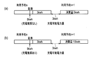
- this charging management system does not present information that recommends charging even if charging can be performed when a sufficient amount of power is charged in the in-vehicle battery by the next use reservation.
- the remaining charge at the time of parking is 8 kwh
- the power consumption up to the return port is 3 kwh
- the chargeable power is 3 kwh.
- the power consumption of the next usage reservation n + 1 is 5 kwh.
- the remaining charge amount of 8 kwh can be secured at the scheduled use start date and time of the next use reservation n + 1. Therefore, even if the vehicle-mounted system 1 detects parking in the use reservation n, it does not present information that recommends charging.
- the charge management system has a remaining charge of 9 kwh at the time of parking in the use reservation n, a power consumption of 3 kwh up to the return port, and a chargeable power Let the amount be 3 kwh.
- the power consumption of the next usage reservation n + 1 is 10 kwh. In this case, there is only a remaining charge of 9 kwh at the scheduled use start date and time of the next use reservation n + 1. Therefore, when the in-vehicle system 1 detects parking in the use reservation n, it presents information that recommends charging.
- this charging management system may switch whether or not to present information recommending charging according to the stay time at the destination.
- the use reservation n includes two destinations and the stay times at the destinations are different.
- the in-vehicle system 1 downloads the schedule for use reservation n from the schedule table database 4 and acquires the stay time at each destination.
- the in-vehicle system 1 refers to the stay time in the parking P ⁇ b> 1 and the stay time in the parking P ⁇ b> 2, and determines that the insufficient power amount can be charged by the stay time in the parking P ⁇ b> 1.
- the in-vehicle system 1 presents information recommending charging when detecting parking corresponding to the staying time in the parking P1. Thereby, the vehicle-mounted system 1 charges the insufficient power amount with the stay time in the parking P1.
- the in-vehicle system 1 does not present information that recommends charging even when parking is detected when the stay time in the next parking P2 is reached.
- the information recommending that the in-vehicle battery be charged during the period in which the vehicle is used by the second usage reservation before the first usage reservation is used for the insufficient power amount of the first usage reservation is used for the insufficient power amount of the first usage reservation. Therefore, insufficient charging of the vehicle can be suppressed.
Landscapes
- Engineering & Computer Science (AREA)
- Power Engineering (AREA)
- Transportation (AREA)
- Mechanical Engineering (AREA)
- Life Sciences & Earth Sciences (AREA)
- Sustainable Development (AREA)
- Sustainable Energy (AREA)
- Electric Propulsion And Braking For Vehicles (AREA)
Abstract
Un système (1) monté sur un véhicule, un dispositif central (2) ou une base de données (4) de programme stockent la date/heure à laquelle un véhicule peut être chargé, et une réservation comportant une date/heure de début d'utilisation programmée du véhicule, une date/heure de fin d'utilisation programmée et une destination établies. Le système de gestion de charge détermine s'il y a suffisamment de puissance pour une première condition de réservation, sur la base d'une valeur de consommation de puissance estimée en fonction de la destination établie pour une réservation ultérieure, et la date/heure à laquelle le véhicule peut être chargé avant la date/heure de début d'utilisation programmée établie par rapport à la première réservation ; et présente des informations de recommandation de charge, par une batterie d'accumulateurs montée sur le véhicule, pendant la période d'utilisation du véhicule par des réservations précédant la réservation ultérieure.
Applications Claiming Priority (2)
| Application Number | Priority Date | Filing Date | Title |
|---|---|---|---|
| JP2012054598 | 2012-03-12 | ||
| JP2012-054598 | 2012-03-12 |
Publications (1)
| Publication Number | Publication Date |
|---|---|
| WO2013137190A1 true WO2013137190A1 (fr) | 2013-09-19 |
Family
ID=49161099
Family Applications (1)
| Application Number | Title | Priority Date | Filing Date |
|---|---|---|---|
| PCT/JP2013/056629 Ceased WO2013137190A1 (fr) | 2012-03-12 | 2013-03-11 | Système et procédé de gestion de charge, et dispositif monté sur un véhicule |
Country Status (1)
| Country | Link |
|---|---|
| WO (1) | WO2013137190A1 (fr) |
Cited By (7)
| Publication number | Priority date | Publication date | Assignee | Title |
|---|---|---|---|---|
| CN106991484A (zh) * | 2016-11-14 | 2017-07-28 | 蔚来汽车有限公司 | 基于智能重复预定的二次资源预约方法 |
| CN109858650A (zh) * | 2019-01-08 | 2019-06-07 | 恒大智慧科技有限公司 | 充电预约方法、计算机设备及存储介质 |
| US10599301B2 (en) | 2015-03-04 | 2020-03-24 | Bang & Olufsen A/S | Panel with a two-hand operated user interface for a multi-room media player |
| CN114254889A (zh) * | 2021-12-08 | 2022-03-29 | 深圳易加油信息科技有限公司 | 充电站车辆排队调度的方法、系统、电子设备及存储介质 |
| CN117172340A (zh) * | 2022-05-24 | 2023-12-05 | 北京骑胜科技有限公司 | 一种借电预约方法、终端、设备、存储介质及产品 |
| CN118211036A (zh) * | 2024-03-30 | 2024-06-18 | 武汉亿纬储能有限公司 | 储能系统的性能分析方法及相关设备 |
| JP2024153505A (ja) * | 2023-04-17 | 2024-10-29 | トヨタ自動車株式会社 | 情報処理装置及び方法 |
Citations (2)
| Publication number | Priority date | Publication date | Assignee | Title |
|---|---|---|---|---|
| JP2009136109A (ja) * | 2007-11-30 | 2009-06-18 | Toyota Motor Corp | 充電制御装置および充電制御方法 |
| JP2011147283A (ja) * | 2010-01-15 | 2011-07-28 | Alpine Electronics Inc | 充電支援システム |
-
2013
- 2013-03-11 WO PCT/JP2013/056629 patent/WO2013137190A1/fr not_active Ceased
Patent Citations (2)
| Publication number | Priority date | Publication date | Assignee | Title |
|---|---|---|---|---|
| JP2009136109A (ja) * | 2007-11-30 | 2009-06-18 | Toyota Motor Corp | 充電制御装置および充電制御方法 |
| JP2011147283A (ja) * | 2010-01-15 | 2011-07-28 | Alpine Electronics Inc | 充電支援システム |
Cited By (10)
| Publication number | Priority date | Publication date | Assignee | Title |
|---|---|---|---|---|
| US10599301B2 (en) | 2015-03-04 | 2020-03-24 | Bang & Olufsen A/S | Panel with a two-hand operated user interface for a multi-room media player |
| CN106991484A (zh) * | 2016-11-14 | 2017-07-28 | 蔚来汽车有限公司 | 基于智能重复预定的二次资源预约方法 |
| WO2018086386A1 (fr) * | 2016-11-14 | 2018-05-17 | 蔚来汽车有限公司 | Procédé de réservation de ressource secondaire basé sur une réservation répétée intelligente |
| CN106991484B (zh) * | 2016-11-14 | 2021-07-23 | 蔚来(安徽)控股有限公司 | 基于智能重复预定的二次资源预约方法 |
| CN109858650A (zh) * | 2019-01-08 | 2019-06-07 | 恒大智慧科技有限公司 | 充电预约方法、计算机设备及存储介质 |
| CN114254889A (zh) * | 2021-12-08 | 2022-03-29 | 深圳易加油信息科技有限公司 | 充电站车辆排队调度的方法、系统、电子设备及存储介质 |
| CN117172340A (zh) * | 2022-05-24 | 2023-12-05 | 北京骑胜科技有限公司 | 一种借电预约方法、终端、设备、存储介质及产品 |
| JP2024153505A (ja) * | 2023-04-17 | 2024-10-29 | トヨタ自動車株式会社 | 情報処理装置及び方法 |
| JP7806752B2 (ja) | 2023-04-17 | 2026-01-27 | トヨタ自動車株式会社 | 情報処理装置及び方法 |
| CN118211036A (zh) * | 2024-03-30 | 2024-06-18 | 武汉亿纬储能有限公司 | 储能系统的性能分析方法及相关设备 |
Similar Documents
| Publication | Publication Date | Title |
|---|---|---|
| JP6595720B2 (ja) | 経路探索装置、バッテリ情報管理装置及びプログラム | |
| JP5553106B2 (ja) | 電力供給制御装置 | |
| JP5693856B2 (ja) | サーバ装置および給電予約受付方法 | |
| EP2645062B1 (fr) | Procédé et système de recherche d'itinéraire pour véhicule automobile électrique | |
| JP6218269B2 (ja) | 電気自動車用充電スタンド案内システム | |
| CN107407570B (zh) | 共享车辆管理装置以及共享车辆管理方法 | |
| JP5238792B2 (ja) | 車載ナビゲーション装置及びサーバ装置 | |
| US20150198459A1 (en) | Method and Apparatus for Electric Vehicle Trip and Recharge Planning | |
| WO2013137190A1 (fr) | Système et procédé de gestion de charge, et dispositif monté sur un véhicule | |
| JP5601008B2 (ja) | 情報提供装置および情報提供方法 | |
| CN102906540A (zh) | 信息提供装置及信息提供方法 | |
| JP6375676B2 (ja) | 共同利用車両の車両管理システム及び車両管理方法 | |
| JP2013115873A (ja) | 車車間電力送受システム、車載電力送受制御装置 | |
| JP2021015087A (ja) | 走行支援装置及びコンピュータプログラム | |
| JP2015094695A (ja) | 電気自動車の走行支援システム | |
| JP6439251B2 (ja) | 車両管理システム及び車両管理方法 | |
| JP6428190B2 (ja) | 共用車両管理装置及び共用車両管理方法 | |
| JP2014155351A (ja) | 情報提供システム | |
| JP6519339B2 (ja) | 共用車両管理装置及び共用車両管理方法 | |
| JP6464847B2 (ja) | 共用車両管理装置及び共用車両管理方法 | |
| JP6428185B2 (ja) | 共用車両管理装置及び共用車両管理方法 | |
| JP2020134487A (ja) | 需要地選択装置および需要地選択方法 | |
| JP2014228374A (ja) | 情報提供装置、情報提供システム、および情報提供方法 | |
| JP7062749B2 (ja) | サーバ装置、その制御方法、およびプログラム | |
| JP2024108740A (ja) | 走行支援装置 |
Legal Events
| Date | Code | Title | Description |
|---|---|---|---|
| 121 | Ep: the epo has been informed by wipo that ep was designated in this application |
Ref document number: 13761014 Country of ref document: EP Kind code of ref document: A1 |
|
| DPE2 | Request for preliminary examination filed before expiration of 19th month from priority date (pct application filed from 20040101) | ||
| NENP | Non-entry into the national phase |
Ref country code: DE |
|
| 122 | Ep: pct application non-entry in european phase |
Ref document number: 13761014 Country of ref document: EP Kind code of ref document: A1 |
|
| NENP | Non-entry into the national phase |
Ref country code: JP |