WO2013137193A1 - 空気入りタイヤ - Google Patents
空気入りタイヤ Download PDFInfo
- Publication number
- WO2013137193A1 WO2013137193A1 PCT/JP2013/056637 JP2013056637W WO2013137193A1 WO 2013137193 A1 WO2013137193 A1 WO 2013137193A1 JP 2013056637 W JP2013056637 W JP 2013056637W WO 2013137193 A1 WO2013137193 A1 WO 2013137193A1
- Authority
- WO
- WIPO (PCT)
- Prior art keywords
- shoulder
- sipe
- tire
- groove
- axial direction
- Prior art date
- Legal status (The legal status is an assumption and is not a legal conclusion. Google has not performed a legal analysis and makes no representation as to the accuracy of the status listed.)
- Ceased
Links
Images


Classifications
-
- B—PERFORMING OPERATIONS; TRANSPORTING
- B60—VEHICLES IN GENERAL
- B60C—VEHICLE TYRES; TYRE INFLATION; TYRE CHANGING; CONNECTING VALVES TO INFLATABLE ELASTIC BODIES IN GENERAL; DEVICES OR ARRANGEMENTS RELATED TO TYRES
- B60C11/00—Tyre tread bands; Tread patterns; Anti-skid inserts
- B60C11/03—Tread patterns
- B60C11/12—Tread patterns characterised by the use of narrow slits or incisions, e.g. sipes
- B60C11/1259—Depth of the sipe
- B60C11/1263—Depth of the sipe different within the same sipe
-
- B—PERFORMING OPERATIONS; TRANSPORTING
- B60—VEHICLES IN GENERAL
- B60C—VEHICLE TYRES; TYRE INFLATION; TYRE CHANGING; CONNECTING VALVES TO INFLATABLE ELASTIC BODIES IN GENERAL; DEVICES OR ARRANGEMENTS RELATED TO TYRES
- B60C11/00—Tyre tread bands; Tread patterns; Anti-skid inserts
- B60C11/03—Tread patterns
- B60C11/0306—Patterns comprising block rows or discontinuous ribs
-
- B—PERFORMING OPERATIONS; TRANSPORTING
- B60—VEHICLES IN GENERAL
- B60C—VEHICLE TYRES; TYRE INFLATION; TYRE CHANGING; CONNECTING VALVES TO INFLATABLE ELASTIC BODIES IN GENERAL; DEVICES OR ARRANGEMENTS RELATED TO TYRES
- B60C11/00—Tyre tread bands; Tread patterns; Anti-skid inserts
- B60C11/03—Tread patterns
- B60C11/04—Tread patterns in which the raised area of the pattern consists only of continuous circumferential ribs, e.g. zig-zag
-
- B—PERFORMING OPERATIONS; TRANSPORTING
- B60—VEHICLES IN GENERAL
- B60C—VEHICLE TYRES; TYRE INFLATION; TYRE CHANGING; CONNECTING VALVES TO INFLATABLE ELASTIC BODIES IN GENERAL; DEVICES OR ARRANGEMENTS RELATED TO TYRES
- B60C11/00—Tyre tread bands; Tread patterns; Anti-skid inserts
- B60C11/03—Tread patterns
- B60C11/12—Tread patterns characterised by the use of narrow slits or incisions, e.g. sipes
- B60C11/1236—Tread patterns characterised by the use of narrow slits or incisions, e.g. sipes with special arrangements in the tread pattern
-
- B—PERFORMING OPERATIONS; TRANSPORTING
- B60—VEHICLES IN GENERAL
- B60C—VEHICLE TYRES; TYRE INFLATION; TYRE CHANGING; CONNECTING VALVES TO INFLATABLE ELASTIC BODIES IN GENERAL; DEVICES OR ARRANGEMENTS RELATED TO TYRES
- B60C11/00—Tyre tread bands; Tread patterns; Anti-skid inserts
- B60C11/03—Tread patterns
- B60C11/13—Tread patterns characterised by the groove cross-section, e.g. for buttressing or preventing stone-trapping
- B60C11/1307—Tread patterns characterised by the groove cross-section, e.g. for buttressing or preventing stone-trapping with special features of the groove walls
-
- B—PERFORMING OPERATIONS; TRANSPORTING
- B60—VEHICLES IN GENERAL
- B60C—VEHICLE TYRES; TYRE INFLATION; TYRE CHANGING; CONNECTING VALVES TO INFLATABLE ELASTIC BODIES IN GENERAL; DEVICES OR ARRANGEMENTS RELATED TO TYRES
- B60C11/00—Tyre tread bands; Tread patterns; Anti-skid inserts
- B60C11/03—Tread patterns
- B60C11/12—Tread patterns characterised by the use of narrow slits or incisions, e.g. sipes
-
- B—PERFORMING OPERATIONS; TRANSPORTING
- B60—VEHICLES IN GENERAL
- B60C—VEHICLE TYRES; TYRE INFLATION; TYRE CHANGING; CONNECTING VALVES TO INFLATABLE ELASTIC BODIES IN GENERAL; DEVICES OR ARRANGEMENTS RELATED TO TYRES
- B60C11/00—Tyre tread bands; Tread patterns; Anti-skid inserts
- B60C11/03—Tread patterns
- B60C2011/0337—Tread patterns characterised by particular design features of the pattern
- B60C2011/0339—Grooves
- B60C2011/0358—Lateral grooves, i.e. having an angle of 45 to 90 degees to the equatorial plane
- B60C2011/0367—Lateral grooves, i.e. having an angle of 45 to 90 degees to the equatorial plane characterised by depth
- B60C2011/0369—Lateral grooves, i.e. having an angle of 45 to 90 degees to the equatorial plane characterised by depth with varying depth of the groove
-
- B—PERFORMING OPERATIONS; TRANSPORTING
- B60—VEHICLES IN GENERAL
- B60C—VEHICLE TYRES; TYRE INFLATION; TYRE CHANGING; CONNECTING VALVES TO INFLATABLE ELASTIC BODIES IN GENERAL; DEVICES OR ARRANGEMENTS RELATED TO TYRES
- B60C11/00—Tyre tread bands; Tread patterns; Anti-skid inserts
- B60C11/03—Tread patterns
- B60C2011/0337—Tread patterns characterised by particular design features of the pattern
- B60C2011/0339—Grooves
- B60C2011/0358—Lateral grooves, i.e. having an angle of 45 to 90 degees to the equatorial plane
- B60C2011/0372—Lateral grooves, i.e. having an angle of 45 to 90 degees to the equatorial plane with particular inclination angles
-
- B—PERFORMING OPERATIONS; TRANSPORTING
- B60—VEHICLES IN GENERAL
- B60C—VEHICLE TYRES; TYRE INFLATION; TYRE CHANGING; CONNECTING VALVES TO INFLATABLE ELASTIC BODIES IN GENERAL; DEVICES OR ARRANGEMENTS RELATED TO TYRES
- B60C11/00—Tyre tread bands; Tread patterns; Anti-skid inserts
- B60C11/03—Tread patterns
- B60C2011/0337—Tread patterns characterised by particular design features of the pattern
- B60C2011/0339—Grooves
- B60C2011/0381—Blind or isolated grooves
-
- B—PERFORMING OPERATIONS; TRANSPORTING
- B60—VEHICLES IN GENERAL
- B60C—VEHICLE TYRES; TYRE INFLATION; TYRE CHANGING; CONNECTING VALVES TO INFLATABLE ELASTIC BODIES IN GENERAL; DEVICES OR ARRANGEMENTS RELATED TO TYRES
- B60C11/00—Tyre tread bands; Tread patterns; Anti-skid inserts
- B60C11/03—Tread patterns
- B60C2011/0337—Tread patterns characterised by particular design features of the pattern
- B60C2011/0386—Continuous ribs
- B60C2011/0388—Continuous ribs provided at the equatorial plane
-
- B—PERFORMING OPERATIONS; TRANSPORTING
- B60—VEHICLES IN GENERAL
- B60C—VEHICLE TYRES; TYRE INFLATION; TYRE CHANGING; CONNECTING VALVES TO INFLATABLE ELASTIC BODIES IN GENERAL; DEVICES OR ARRANGEMENTS RELATED TO TYRES
- B60C11/00—Tyre tread bands; Tread patterns; Anti-skid inserts
- B60C11/03—Tread patterns
- B60C11/12—Tread patterns characterised by the use of narrow slits or incisions, e.g. sipes
- B60C11/1204—Tread patterns characterised by the use of narrow slits or incisions, e.g. sipes with special shape of the sipe
- B60C2011/1209—Tread patterns characterised by the use of narrow slits or incisions, e.g. sipes with special shape of the sipe straight at the tread surface
Definitions
- the present invention relates to a pneumatic tire having high wet performance while maintaining steering stability and wear resistance.
- pneumatic tires with various shapes of drainage grooves have been proposed.
- a pneumatic tire provided with a sipe with a narrow groove width has also been proposed.
- the latter pneumatic tire has higher wet performance due to the water absorption effect and edge effect of sipe.
- tread portion provided with the sipe tends to have low rigidity, such tires tend to have low steering stability and wear resistance.
- Patent Document 1 discloses a pneumatic tire including improved circumferential grooves, sipes, and blocks in order to improve uneven wear resistance and riding comfort while maintaining wet performance.
- a pneumatic tire has room for further improvement in handling stability.
- the present invention has been devised in view of the above circumstances, and its main object is to provide a pneumatic tire having high wet performance while maintaining steering stability and wear resistance.
- the present invention provides a pair of crown main grooves extending continuously in the tire circumferential direction on both sides of the tire equator on the tread portion, and a pair of shoulder main grooves extending continuously in the tire circumferential direction on the outer side in the tire axial direction of the crown main grooves.
- a pneumatic tire provided with a pair of middle land portions between the crown main groove and the shoulder main groove, the inner end of the tire in the axial direction of the middle land portion being the crown main groove
- a middle sipe that communicates with the shoulder main groove at the outer end in the tire axial direction, and a middle sub-groove extending between the middle sipes adjacent in the tire circumferential direction without intersecting the middle sipe
- the middle sipe has an arc shape in which an angle with respect to a tire circumferential direction gradually increases from the inner end toward the outer end, and the middle sipe extends from the outer end to the inner end.
- the length in the circumferential direction is 0.6 to 1.0 times the arrangement pitch of the middle sipes, and the middle sub-groove communicates with the shoulder main groove at the outer end in the tire axial direction.
- the inner end in the axial direction terminates without communicating with the crown main groove, and the middle sub-groove has an arc shape in which an angle with respect to a tire circumferential direction gradually increases from the inner end toward the outer end,
- the length in the tire circumferential direction from the outer end to the inner end of the groove is smaller than the length in the tire circumferential direction of the middle sipe, and the middle sipe adjacent to the tire circumferential direction and the middle sub-groove are in the tire axial direction. It is characterized by overlapping each other.
- the middle land portion is provided with a middle auxiliary sipe between the middle sipe and the middle subgroove adjacent in the tire circumferential direction, and the middle auxiliary sipe is arranged in the tire axial direction.
- the outer end communicates with the shoulder main groove, the inner end in the tire axial direction terminates outside the inner end of the middle sub-groove in the tire axial direction, and the middle auxiliary sipe has an angle with respect to the tire circumferential direction.
- a pneumatic tire having an arc shape that gradually increases from the inner end toward the outer end is provided.
- a shoulder land portion is formed on the outer side in the tire axial direction of each shoulder main groove, and the shoulder land portion extends at least inward in the tire axial direction from the tread ground contact end, and the shoulder
- a plurality of shoulder lateral grooves having inner ends that terminate without communicating with the main groove are provided, and the shoulder land portion is provided with a plurality of shoulder first portions partitioned between the shoulder lateral grooves adjacent in the tire circumferential direction.
- the shoulder first portion is provided with a shoulder sipe, and the shoulder sipe has an inner end in the tire axial direction communicating with the shoulder main groove, and an outer end in the tire axial direction is at least a tread grounding end.
- the circular arc is positioned, and 70% or more of the plurality of shoulder first portions has at least two shoulder sipes.
- a pneumatic tire which is provided is provided.
- a pneumatic tire in which a radius of curvature of the shoulder sipe is smaller than a radius of curvature of the middle sipe.
- a pneumatic tire in which the shoulder sipe has a sipe depth on the outer end side larger than a sipe depth on the inner end side.
- a pneumatic tire in which the shoulder sipe has a radius of curvature of 30 to 60 mm.
- the pneumatic tire of the present invention can exhibit high wet performance while maintaining steering stability and wear resistance.
- FIG. 2 is a development view of the tread portion of FIG. 1.
- FIG. 3 is an enlarged development view of a crown land portion of FIG. 2.
- FIG. 3 is an enlarged development view of a middle land portion of FIG. 2.
- FIG. 3 is an enlarged development view of a shoulder land portion of FIG. 2.
- FIG. 6 is an enlarged cross-sectional view taken along a line AA in FIG.
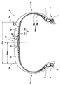
- FIG. 1 is a tire meridian cross-sectional view including a tire rotation axis in a normal state of the pneumatic tire 1 of the present embodiment.
- the normal state is a no-load state in which the tire is assembled on a normal rim (not shown) and filled with a normal internal pressure.
- dimensions and the like of each part of the tire are values measured in this normal state.
- the “regular rim” is a rim determined for each tire in the standard system including the standard on which the tire is based. For example, if it is JATMA, “standard rim”, if it is TRA, “Design Rim”, For ETRTO, it is “Measuring” Rim.
- the “regular internal pressure” is an air pressure determined by each standard for each tire in the standard system including the standard on which the tire is based.
- “maximum air pressure” for TRA, “TIRE” LOAD The maximum value described in LIMITS AT AT VARIOUS COLD INFLATION “PRESSURES”, or “INFLATION PRESSURE” in ETRTO.
- the pneumatic tire 1 of the present embodiment includes a carcass 6 that extends from a tread portion 2 through a sidewall portion 3 to a bead core 5 of the bead portion 4, and the carcass 6 has an outer side in the tire radial direction and a tread.
- a belt layer 7 disposed inward of the portion 2 is provided, and in this embodiment, a thing for a passenger car is shown.
- the carcass 6 is composed of, for example, one carcass ply 6A.
- the carcass ply 6A includes a main body portion 6a extending between the bead cores 5 and 5 and a folded portion 6b that is turned around the bead core 5 from the inner side to the outer side in the tire axial direction.
- a bead apex rubber 8 extending in a tapered manner from the bead core 5 toward the outer side in the tire radial direction is disposed between the main body portion 6a and the folded portion 6b.
- the carcass ply 6A has carcass cords arranged at an angle of 70 to 90 ° with respect to the tire equator C, for example.
- As the carcass cord for example, an organic fiber cord such as aromatic polyamide or rayon is used.
- the belt layer 7 is composed of two belt plies 7A and 7B.
- Each belt ply 7A, 7B has a belt cord arranged at an angle of, for example, 15 to 45 degrees with respect to the tire equator C, and is overlapped so that the belt cords cross each other.
- the belt cord for example, steel cord, aramid, rayon, or the like is suitably employed.
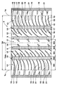
- FIG. 2 shows a development view of the tread portion 2 of the pneumatic tire 1 of the present embodiment.
- the tread portion 2 includes a pair of crown main grooves 9 disposed on both sides of the tire equator C and continuously extending in the tire circumferential direction, and the outer sides of the crown main grooves 9 extending in the tire circumferential direction.
- a pair of shoulder main grooves 10 extending continuously are provided.
- the tread portion 2 is provided with a crown land portion 11 between the pair of crown main grooves 9, 9, a middle land portion 12 between the crown main groove 9 and the shoulder main groove 10, 12 and shoulder land portions 13 and 13 on the outer side in the tire axial direction of the shoulder main groove 10 are divided.
- the tread portion 2 has a land ratio of preferably 64% or more, more preferably 66% or more, preferably 72% or less, more preferably 70% or less, depending on each groove and each land portion. Thereby, dry performance and wet performance are exhibited with good balance.
- the “land ratio” means the ratio of the actual ground contact area to the total area of the virtual ground contact surface that fills all the grooves between the tread ground contact Te and Te.
- the tread grounding end Te means a grounding end on the outermost side in the tire axial direction when a normal load is applied to the tire in the normal state and grounded on a flat surface with a camber angle of 0 degree.
- the “regular load” is a load determined by each standard for each tire in a standard system including the standard on which the tire is based.
- “JATMA” indicates “maximum load capacity”, and TRA indicates “TIRE”. The maximum value described in LOAD, LIMITS, AT, VARIOUS, COLD, INFLATION, PRESSURES, and LOAD, CAPACITY for ETRTO.
- the crown main groove 9 extends, for example, linearly in the tire circumferential direction so as to effectively discharge a water film generated in the vicinity of the tire equator C during wet running.
- the crown main groove 9 is not limited to such a shape, and may extend in a zigzag shape or a wave shape.
- the groove width W1 of the crown main groove 9 is preferably 9% or more, more preferably 10% or more, preferably 13% or less of the tread half width TWh. Is 12% or less.
- the tread half-width TWh is a distance in the tire axial direction from the tire equator C to one tread ground contact end Te.
- the groove width W1 is desirably set in the range of 8 to 12 mm.
- the groove depth d1 of the crown main groove 9 is preferably set in the range of 7 to 9 mm.
- the shoulder main groove 10 extends linearly in the tire circumferential direction, like the crown main groove 9. However, the shoulder main groove 10 may extend in a zigzag shape or a wave shape.
- the groove width W2 of the shoulder main groove 10 is preferably 10% or more, more preferably 11% or more of the tread half width TWh, and preferably 14% or less. Preferably it is 13% or less. From the same viewpoint, it is desirable that the groove depth d2 of the shoulder main groove 10 is set in the range of 7 to 9 mm. In particular, the groove width W2 of the shoulder main groove 10 is desirably larger than the groove width W1 of the crown main groove 9.
- FIG. 3 shows an enlarged development view of the crown land portion 11. As shown in FIG. 3, the crown land portion 11 is provided on the tire equator C.
- the width W3 in the tire axial direction between the side edges 11e, 11e on the ground contact surface of the crown land portion 11 is preferably 22% or more of the tread half width TWh, More preferably, it is 24% or more, preferably 28% or less, more preferably 26% or less.
- an inclined crown sub-groove 14 extending from the crown main groove 9 toward the tire equator C is provided. Thereby, drainage capability is raised and wet performance further improves.
- the groove length L1 of the crown auxiliary groove 14 in the tire axial direction is preferably 6% or more, more preferably 7% or more of the tread half-width TWh. In addition, it is preferably 11% or less, more preferably 10% or less. From the same viewpoint, it is desirable that the groove width of the crown sub-groove 14 is in the range of 2.5 to 3.5 mm and the groove depth is in the range of 4.5 to 6.5 mm.
- the arrangement pitch P1 of the crown sub-groove 14 in the tire circumferential direction is preferably 3% or more, more preferably 4% or more of the tire outer diameter. And preferably 7% or less, more preferably 6% or less.
- FIG. 4 shows an enlarged development view of the middle land portion 12.
- the middle land portion 12 is provided with a plurality of middle sipes 15 and a plurality of middle subgrooves 16.
- the width W4 of the middle land portion 12 is preferably set larger than the width W3 of the crown land portion 11. Thereby, the ground contact pressure of the crown land portion 11 and the middle land portion 12 is optimized, and uneven wear is suppressed.
- the width W4 is preferably at least 24% of the tread half width TWh, more preferably at least 26%, and more preferably at most 32%, in order to improve the dry performance, wear resistance and wet performance in a balanced manner. Preferably it is 30% or less. In the case of the passenger car tire of this embodiment, the width W4 is preferably in the range of 20 to 25 mm.
- Middle sipes P2 are provided at a pitch P2 in the tire circumferential direction.
- the arrangement pitch P2 is preferably set to 3 to 7% of the tire outer diameter, for example.
- the middle sipe 15 has an inner end 15 i in the tire axial direction communicating with the crown main groove 9 and an outer end 15 o in the tire axial direction communicating with the shoulder main groove 10.
- Such a middle sipe 15 absorbs water between the tread portion 2 and the road surface during wet running, and discharges a part of the water outward in the tire axial direction. Thereby, the wet performance of a tire improves.
- the sipe width of the middle sipe 15 is in the range of 0.6 to 1.0 mm, for example, and the sipe depth is in the range of 2.0 to 3.0 mm, for example. Each is desirable.
- the middle sipe 15 an angle ⁇ 1 with respect to the tire circumferential direction gradually increases from the inner end 15i toward the outer end 15o so as to be curved in an arc shape.
- a middle sipe 15 has a small angle ⁇ 1 on the crown main groove 9 side and a large angle ⁇ 1 on the shoulder main groove 10 side. Therefore, the middle land portion 12 has high circumferential rigidity on the crown main groove 9 side where the ground contact pressure when traveling straight is relatively large, and high axial direction on the shoulder main groove 10 side where the ground pressure becomes relatively large when turning. It has rigidity. For this reason, the rigidity of the middle land portion 12 is appropriately ensured, and steering stability and wear resistance are improved. Furthermore, the arc-shaped middle sipe 15 is preferable in that it has a larger edge length than the straight sipe.
- the angle ⁇ 1 of the middle sipe 15 is in a range of 30 to 40 ° at the inner end 15i and 55 to 65 ° at the outer end 15o in order to maintain a good balance between drainage performance and rigidity in the tire circumferential direction of the middle land portion 12. It is desirable to be in the range.
- the curvature radius R1 indicating the degree of curvature of the middle sipe 15 is preferably 30 mm or more, more preferably 50 mm or more, preferably 90 mm or less. More preferably, it is 70 mm or less.
- the length L2 in the tire circumferential direction from the outer end 15o to the inner end 15i is 0.6 to 1.0 times the arrangement pitch P2.
- the rigidity of the middle land portion 12 and the drainage performance are improved in a well-balanced manner so that steering stability, wear resistance, and wet performance are compatible.
- the length L2 is less than 0.6 times the arrangement pitch P2, the wet performance may be reduced.
- the length L2 is larger than 1.0 times the arrangement pitch P2, the steering stability and the wear resistance may be reduced.
- the middle sub-groove 16 is provided between the middle sipes 15 and 15 adjacent in the tire circumferential direction without intersecting with the middle sipes 15.
- the middle sub-groove 16 has an outer end 16o in the tire axial direction that communicates with the shoulder main groove 10.
- the inner end 16 i in the tire axial direction of the middle sub-groove 16 terminates without communicating with the crown main groove 9.
- Such a middle sub-groove 16 can maintain high rigidity of the middle land portion 12 while improving wet performance so as to improve the steering stability and wear resistance of the tire.
- the middle sub-groove 16 has an angle ⁇ 2 with respect to the tire circumferential direction that gradually increases from the inner end 16i toward the outer end 16o so as to curve and extend in an arc shape. Like the middle sipe 15, such a middle subgroove 16 improves wet performance while improving steering stability and wear resistance.
- the angle ⁇ 2 is preferably set in the range of 40 to 60 °. From the same viewpoint, it is desirable that the groove width of the middle sub-groove 16 is set in the range of 2.0 to 4.0 mm, for example, and the groove depth is set in the range of 4.0 to 7.0 mm, for example.
- the curvature radius R2 indicating the degree of curvature of the middle sub-groove 16 is preferably 25 mm or more, more preferably 45 mm or more, and preferably 75 mm or less, more preferably 55 mm. It is as follows.
- the length L3 in the tire circumferential direction from the outer end 16o to the inner end 16i of the middle sub groove 16 is set to be smaller than the length L2 of the middle sipe 15 in the tire circumferential direction. This prevents a decrease in rigidity of the middle land portion 12 due to the middle sub-groove 16.
- the length L3 of the middle sub-groove 16 is 50% or more of the arrangement pitch P2 of the middle sipes 15, more preferably 60% or more. Moreover, it is preferably 80% or less, more preferably 70% or less.
- the middle sipe 15 and the middle sub-groove 16 that are adjacent in the tire circumferential direction are disposed so as to overlap each other in the tire axial direction. That is, as is apparent from FIG. 4, the straight line Xi obtained by projecting the inner end 15 i of the middle sipe 15 in the tire axial direction intersects the middle sub-groove 16. Similarly, a straight line Xo obtained by projecting the outer end 15 i of the middle sipe 15 in the tire axial direction also intersects with the other middle sub-groove 16. Such arrangement of the middle sipe 15 and the middle sub-groove 16 further improves the wet performance of the tire.
- the overlap distance L4 in the tire circumferential direction between the inner end 15i of the middle sipe 15 and the outer end 16o of the middle sub-groove 16 and the middle sipe 15 is preferably 8% or more, more preferably 10% or more of the arrangement pitch P2 of the middle sipes 15, respectively. Preferably it is 15% or less, More preferably, it is 13% or less.
- the middle land portion 12 is provided with a middle auxiliary sipe 17 between the middle sipe 15 and the middle sub-groove adjacent in the tire circumferential direction.
- the middle auxiliary sipe 17 further enhances the drainage capacity of the middle sipe 15 and the middle sub-groove 16 while making the rigidity of the middle land portion 12 uniform.
- the middle auxiliary sipe 17 has a sipe width in the range of 0.6 to 1.0 mm and a sipe depth in the range of 2.0 to 3.0 mm.
- the middle auxiliary sipe 17 has an outer end 17o in the tire axial direction communicating with the shoulder main groove 10.
- the inner end 17 i in the tire axial direction of the middle auxiliary sipe 17 terminates at the outer side in the tire axial direction than the inner end 16 i of the middle sub-groove 16.
- Such a middle auxiliary sipe 17 can improve drainage performance while maintaining high rigidity on the tire equator side of the middle land portion 12.
- the middle auxiliary sipe 17 has an angle ⁇ 3 with respect to the tire circumferential direction that gradually increases from the inner end 17i toward the outer end 17o so as to extend in an arc shape.
- the middle auxiliary sipe 17 of the present embodiment extends along the middle sipe 15.
- the angle ⁇ 3 is preferably in the range of 45 to 70 ° in order to increase the rigidity and drainage capacity of the middle land portion 12.
- the curvature radius R3 of the middle auxiliary sipe 17 is preferably 30 mm or more, more preferably 50 mm or more, and preferably 90 mm or less, more preferably 70 mm or less.
- a block-shaped middle first portion 26 is divided between the middle sub-grooves 16 and 16 adjacent in the tire circumferential direction. At least one middle first portion 26 is provided with a middle sipe 15 or a middle auxiliary sipe 17. More preferably, the middle first part 26 is provided with one middle sipe 15 and one middle auxiliary sipe 17. Further, at least one middle sipe 15 and middle auxiliary sipe 17 are provided in the middle first portion 26 of preferably 70% or more, more preferably 80% or more of the middle first portion 26 included in the tire. desirable.
- the middle sipe 15, the middle auxiliary groove 16, and the middle auxiliary sipe 17 are inclined in the same direction.
- the middle sipe 15, the middle sub-groove 16, and the middle auxiliary sipe 17 have an arc shape that is convex in the same direction. Thereby, the rigidity of the middle land portion 12 is further uniformed, and the steering stability and the uneven wear resistance are improved.
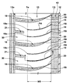
- FIG. 5 shows an enlarged development view of the shoulder land portion 13.
- the shoulder land portion 13 is provided with a plurality of shoulder lateral grooves 18 and a plurality of shoulder sipes 19.
- the width W5 of the shoulder land portion 13 is larger than the width W4 of the middle land portion 12 so that the wear resistance of the middle land portion 12 and the shoulder land portion 13 is improved.
- the width W5 is preferably 44% or more of the tread half width TWh, more preferably 46% or more, and preferably 52% or less, more preferably, in order to improve the steering stability and wear resistance in a balanced manner. 50% or less.
- the shoulder lateral groove 18 extends at least from the tread contact end Te to the inside in the tire axial direction. More preferably, in order to improve the wandering performance, it is desirable that the shoulder lateral groove 18 extends inward in the tire axial direction from a position outside in the tire axial direction from the tread ground contact end Te.
- the shoulder lateral groove 18 has an inner end 18 i that terminates without communicating with the shoulder main groove 10.
- the shoulder land portion 13 has high rigidity on the inner side in the tire axial direction, so that steering stability is improved.
- the width of the shoulder lateral groove 18 is set in the range of 2.0 to 5.0 mm, for example, and the depth of the groove is set in the range of 4.0 to 7.0 mm, for example.
- the shoulder lateral groove 18 has an arc shape that is convex in the same direction as the middle sub-groove 16 of the adjacent middle land portion 12. Thereby, the rigidity of the middle land portion 12 and the shoulder land portion 13 is made uniform, and uneven wear is suppressed.
- a shoulder auxiliary sipe 20 that communicates with both is preferably provided. Thereby, the drainage property of the shoulder main groove 10 is further enhanced while the rigidity of the shoulder land portion 13 is secured, and the wet performance is improved while maintaining the steering stability and the wear resistance.
- the shoulder sipe 19 is provided between the shoulder lateral grooves 18 and 18 adjacent in the tire circumferential direction.
- the shoulder sipe 19 preferably has an inner end 19 i in the tire axial direction communicating with the shoulder main groove 10. Thereby, the drainage property of the shoulder main groove 10 is further improved.
- the outer end 19o of the shoulder sipe 19 in the tire axial direction is preferably positioned at least at the tread ground contact Te.
- the outer end 19o of the shoulder sipe 19 is provided at a position beyond the tread grounding end Te so as to further improve the wet performance.
- the shoulder land portion 13 is divided into a plurality of shoulder first portions 30.
- Each shoulder first portion 30 is provided between shoulder lateral grooves 18 and 18 adjacent in the tire circumferential direction.
- At least one shoulder first portion 30 is desirably provided with at least one shoulder sipe 19, more preferably two.
- at least two shoulder sipes 19 are provided in the shoulder first portion 30 that is preferably 70% or more, more preferably 80% or more, of the shoulder first portion 30 included in the tire 1. .
- the shoulder sipe 19 preferably extends in an arc shape. More preferably, the shoulder sipe 19 has an arc shape that is convex in the same direction as the middle sipe 15. Thereby, the turning property at the time of wet traveling further improves. Desirably, the curvature radius R4 indicating the degree of curvature of the shoulder sipe 19 is smaller than the curvature radius R1 of the middle sipe 15. Thereby, the said edge effect of the shoulder land part 13 is exhibited further.
- the curvature radius R4 is preferably 30 mm or more, more preferably 40 mm or more, and preferably 70 mm or less, more preferably 60 mm or less in order to balance wet performance and steering stability.
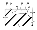
- FIG. 6 shows a cross-sectional view of the shoulder sipe 19 of FIG.
- the shoulder sipe 19 preferably has a sipe depth do on the outer end 19o side larger than a sipe depth di on the inner end 19i side. More preferably, the shoulder sipe 19 includes a portion where the sipe depth gradually increases from the inner end 19i side toward the outer end 19o side. Thereby, the rigidity inside the tire axial direction of the shoulder land portion 13 is relatively increased, and uneven wear resistance is improved.
- a shoulder sub-groove 21 is provided between the shoulder lateral grooves 18 and 18 adjacent in the tire circumferential direction.
- the shoulder sub-groove 21 extends from the edge 13o on the outer side in the tire axial direction of the shoulder land portion 13 toward the inner side in the tire axial direction so as to improve the wandering performance, and terminates without reaching the tread ground contact end Te.
- the length of the shoulder minor groove 21 in the tire axial direction is smaller than the shoulder lateral groove 18.
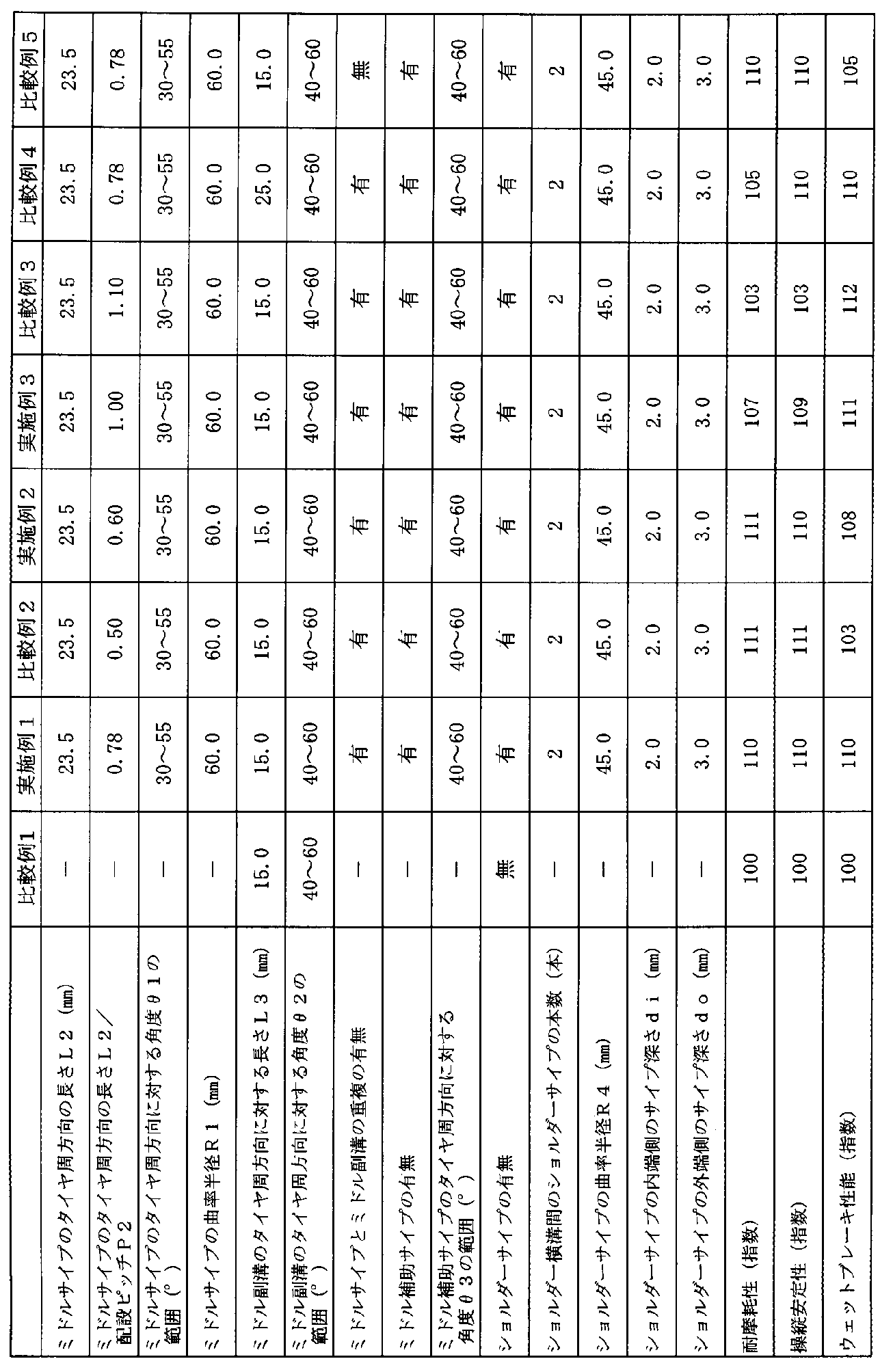
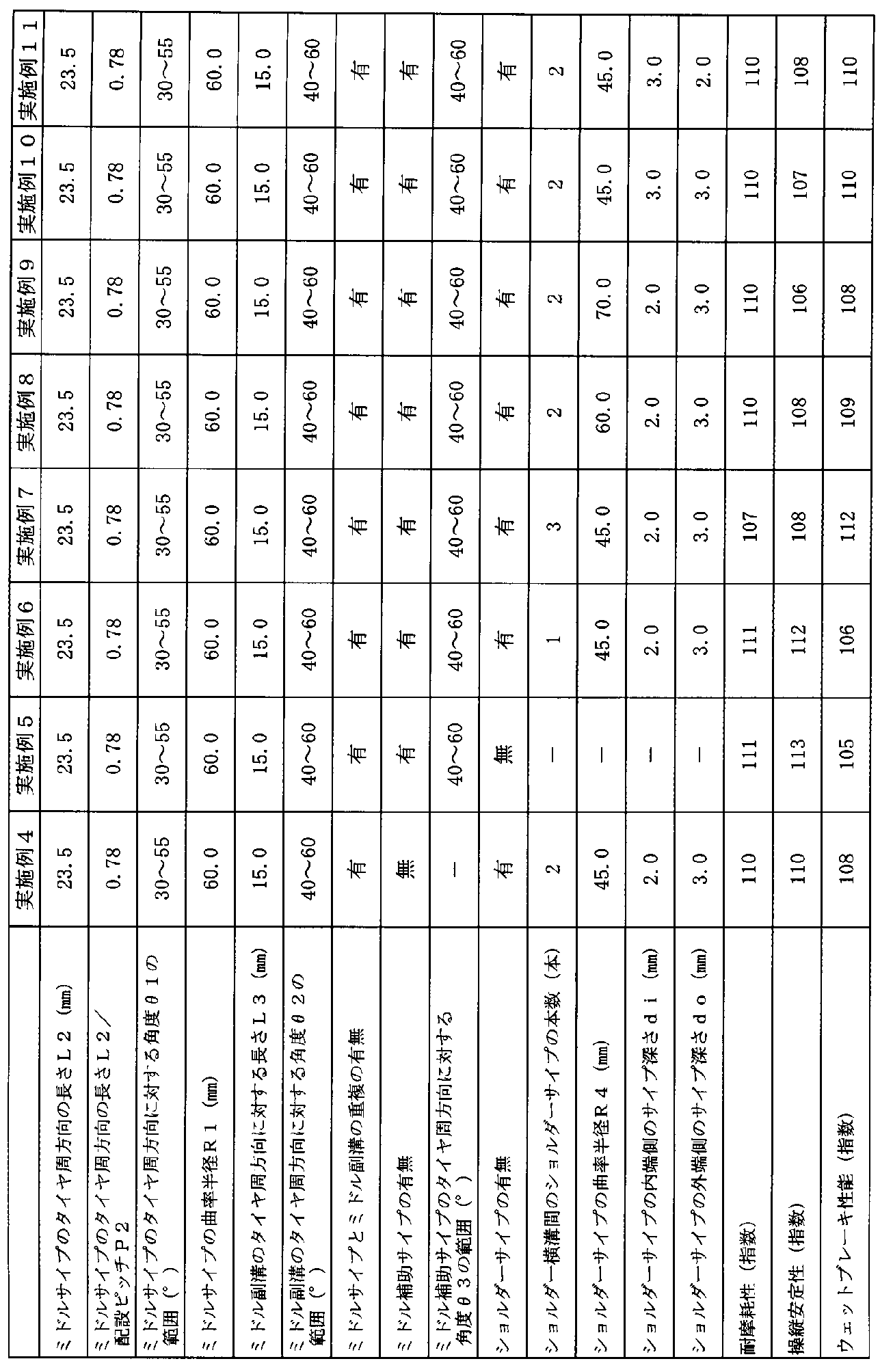
- Pneumatic tires of size 195 / 60R14 having the basic structure shown in Fig. 1 were prototyped based on the specifications shown in Table 1 and tested for wear resistance and wet brake performance.
- a tire without a middle sipe, a middle auxiliary sipe, and a shoulder sipe was similarly tested.
- the test method is as follows.
- Abrasion resistance The test tire mounted on the rim 14 ⁇ 7J was mounted on all wheels of a passenger car with an internal pressure of 230 kPa and a displacement of 1600 cc, and the groove depth of the crown main groove after traveling 5000 km was measured.
- a result is an index
- Steering stability performance The vehicle was run on a dry asphalt road test track with one driver on board, and the characteristics relating to steering response, rigidity, grip, etc. during turning were evaluated by sensory evaluation of the driver. A result is an index which sets comparative example 1 as 100, and shows that steering stability performance is excellent, so that a numerical value is large.
- Wet brake performance With the vehicle, the braking distance until the vehicle entered the wet asphalt road surface with a water film of 1.4 to 1.6 mm at 60 km / h and completely braked was measured. The result is the reciprocal of the braking distance, and is indicated by an index with Comparative Example 1 being 100. The larger the value, the better the wet brake performance.
Landscapes
- Engineering & Computer Science (AREA)
- Mechanical Engineering (AREA)
- Tires In General (AREA)
Abstract
Description
図1は、本実施形態の空気入りタイヤ1の正規状態におけるタイヤ回転軸を含むタイヤ子午線断面図である。ここで、正規状態とは、タイヤが正規リム(図示省略)にリム組みされ、かつ、正規内圧が充填された無負荷の状態である。以下、特に言及されない場合、タイヤの各部の寸法等は、この正規状態で測定された値である。
ドライ性能、ウェット性能及び耐摩耗性を向上させるために、クラウン陸部11の接地面での側縁11e、11e間のタイヤ軸方向の幅W3は、好ましくは、トレッド半幅TWhの22%以上、より好ましくは24%以上であり、好ましくは28%以下、より好ましくは26%以下である。
リム14×7Jに装着されたテストタイヤが、内圧230kPaで、排気量1600ccの乗用車の全輪に装着され、5000km走行後のクラウン主溝の溝深さが測定された。結果は、比較例1を100とする指数であり、数値が大きい程、耐摩耗性能に優れていることを示す。
前記車両にて、ドライアスファルト路面のテストコースをドライバー1名乗車で走行し、旋回時のハンドル応答性、剛性感及びグリップ等に関する特性が、ドライバーの官能評価により評価された。結果は、比較例1を100とする指数であり、数値が大きい程、操縦安定性能が優れていることを示す。
前記車両にて、水膜1.4~1.6mmのウェットアスファルト路面に60km/hで進入し、完全制動するまでの制動距離が測定された。結果は、制動距離の逆数であり、比較例1を100とする指数で示されている。数値が大きい程、ウェットブレーキ性能が優れていることを示す。
10 ショルダー主溝
11 クラウン陸部
12 ミドル陸部
13 ショルダー陸部
14 クラウン副溝
15 ミドルサイプ
16 ミドル副溝
17 ミドル補助サイプ
18 ショルダー横溝
19 ショルダーサイプ
20 ショルダー補助サイプ
21 ショルダー副溝
Claims (6)
- トレッド部に、タイヤ赤道の両側をタイヤ周方向に連続してのびる一対のクラウン主溝、前記クラウン主溝のタイヤ軸方向外側をタイヤ周方向に連続してのびる一対のショルダー主溝、及び、前記クラウン主溝と前記ショルダー主溝との間の一対のミドル陸部が設けられた空気入りタイヤであって、
前記ミドル陸部には、タイヤ軸方向の内端が前記クラウン主溝に連通し、かつ、タイヤ軸方向の外端が前記ショルダー主溝に連通するミドルサイプと、
タイヤ周方向で隣り合う前記ミドルサイプ間を前記ミドルサイプと交差することなくのびるミドル副溝とが設けられ、
前記ミドルサイプは、タイヤ周方向に対する角度が前記内端から前記外端に向かって漸増する円弧状であり、
前記ミドルサイプの前記外端から前記内端までのタイヤ周方向の長さは、前記ミドルサイプの配設ピッチの0.6~1.0倍であり、
前記ミドル副溝は、タイヤ軸方向の外端が前記ショルダー主溝に連通し、かつ、タイヤ軸方向の内端が前記クラウン主溝に連通することなく終端し、
前記ミドル副溝は、タイヤ周方向に対する角度が前記内端から前記外端に向かって漸増する円弧状であり、
前記ミドル副溝の前記外端から前記内端までのタイヤ周方向の長さは、前記ミドルサイプのタイヤ周方向の長さよりも小さく、
タイヤ周方向で隣り合う前記ミドルサイプと前記ミドル副溝とは、タイヤ軸方向で互いに重複することを特徴とする空気入りタイヤ。 - 前記ミドル陸部には、タイヤ周方向で隣り合う前記ミドルサイプと前記ミドル副溝との間にミドル補助サイプが設けられ、
前記ミドル補助サイプは、タイヤ軸方向の外端が前記ショルダー主溝に連通し、かつ、タイヤ軸方向の内端が前記ミドル副溝の前記内端よりもタイヤ軸方向外側で終端し、
前記ミドル補助サイプは、タイヤ周方向に対する角度が前記内端から前記外端に向かって漸増する円弧状である請求項1記載の空気入りタイヤ。 - 前記各ショルダー主溝のタイヤ軸方向外側にショルダー陸部が形成され、
前記ショルダー陸部には、少なくともトレッド接地端からタイヤ軸方向内側にのび、かつ、前記ショルダー主溝に連通することなく終端する内端を有するショルダー横溝が複数本設けられ、
前記ショルダー陸部は、タイヤ周方向で隣り合う前記ショルダー横溝間で区分されたショルダー第1部分が複数個設けられ、
前記ショルダー第1部分には、ショルダーサイプが設けられ、
前記ショルダーサイプは、タイヤ軸方向の内端が前記ショルダー主溝に連通し、かつ、タイヤ軸方向の外端側は少なくともトレッド接地端に位置する円弧状であり、
前記複数個のショルダー第1部分のうちの70%以上は、前記ショルダーサイプが少なくとも2本設けられている請求項1記載の空気入りタイヤ。 - 前記ショルダーサイプの曲率半径は、前記ミドルサイプの曲率半径よりも小さい請求項3記載の空気入りタイヤ。
- 前記ショルダーサイプは、前記外端側のサイプ深さが、前記内端側でのサイプ深さよりも大きい請求項3記載の空気入りタイヤ。
- 前記ショルダーサイプの曲率半径は、30~60mmである請求項3記載の空気入りタイヤ。
Priority Applications (5)
| Application Number | Priority Date | Filing Date | Title |
|---|---|---|---|
| AU2013233313A AU2013233313B2 (en) | 2012-03-15 | 2013-03-11 | Pneumatic tire |
| CN201380012005.XA CN104144802B (zh) | 2012-03-15 | 2013-03-11 | 充气轮胎 |
| EP13761727.0A EP2818334B1 (en) | 2012-03-15 | 2013-03-11 | Pneumatic tire |
| KR1020147026578A KR102030715B1 (ko) | 2012-03-15 | 2013-03-11 | 공기 타이어 |
| US14/380,954 US9789736B2 (en) | 2012-03-15 | 2013-03-11 | Pneumatic tire |
Applications Claiming Priority (2)
| Application Number | Priority Date | Filing Date | Title |
|---|---|---|---|
| JP2012-059098 | 2012-03-15 | ||
| JP2012059098A JP5629283B2 (ja) | 2012-03-15 | 2012-03-15 | 空気入りタイヤ |
Publications (1)
| Publication Number | Publication Date |
|---|---|
| WO2013137193A1 true WO2013137193A1 (ja) | 2013-09-19 |
Family
ID=49161102
Family Applications (1)
| Application Number | Title | Priority Date | Filing Date |
|---|---|---|---|
| PCT/JP2013/056637 Ceased WO2013137193A1 (ja) | 2012-03-15 | 2013-03-11 | 空気入りタイヤ |
Country Status (7)
| Country | Link |
|---|---|
| US (1) | US9789736B2 (ja) |
| EP (1) | EP2818334B1 (ja) |
| JP (1) | JP5629283B2 (ja) |
| KR (1) | KR102030715B1 (ja) |
| CN (3) | CN108944273B (ja) |
| AU (1) | AU2013233313B2 (ja) |
| WO (1) | WO2013137193A1 (ja) |
Cited By (9)
| Publication number | Priority date | Publication date | Assignee | Title |
|---|---|---|---|---|
| EP2792505A1 (en) * | 2013-04-15 | 2014-10-22 | Sumitomo Rubber Industries, Ltd. | Pneumatic tire |
| CN105415984A (zh) * | 2014-09-17 | 2016-03-23 | 住友橡胶工业株式会社 | 充气轮胎 |
| US20160144664A1 (en) * | 2014-11-20 | 2016-05-26 | Sumitomo Rubber Industries Ltd. | Pneumatic tire |
| JP2017165140A (ja) * | 2016-03-14 | 2017-09-21 | 株式会社ブリヂストン | 重荷重用ラジアルタイヤ |
| US10035380B2 (en) * | 2014-05-29 | 2018-07-31 | Bridgestone Corporation | Pneumatic tire |
| US10933697B2 (en) | 2015-07-27 | 2021-03-02 | The Yokohama Rubber Co., Ltd. | Pneumatic tire |
| JP2023062370A (ja) * | 2021-10-21 | 2023-05-08 | Toyo Tire株式会社 | タイヤ |
| JP2023062446A (ja) * | 2021-10-21 | 2023-05-08 | Toyo Tire株式会社 | タイヤ |
| US11654725B2 (en) | 2018-01-30 | 2023-05-23 | The Yokohama Rubber Co., Ltd. | Pneumatic tire |
Families Citing this family (33)
| Publication number | Priority date | Publication date | Assignee | Title |
|---|---|---|---|---|
| JP5981900B2 (ja) * | 2013-10-03 | 2016-08-31 | 住友ゴム工業株式会社 | 空気入りタイヤ |
| FR3012768B1 (fr) * | 2013-11-05 | 2016-12-23 | Michelin & Cie | Bande de roulement comportant un bloc presentant une pluralite d'incisions |
| JP5997729B2 (ja) * | 2014-07-17 | 2016-09-28 | 住友ゴム工業株式会社 | 空気入りタイヤ |
| JP6382647B2 (ja) | 2014-08-29 | 2018-08-29 | 株式会社ブリヂストン | 空気入りタイヤ |
| JP6231974B2 (ja) * | 2014-11-27 | 2017-11-15 | 住友ゴム工業株式会社 | 空気入りタイヤ |
| FR3030371A1 (fr) * | 2014-12-23 | 2016-06-24 | Michelin & Cie | Bande de roulement pour pneu hivernal poids lourd |
| JP6063918B2 (ja) * | 2014-12-26 | 2017-01-18 | 住友ゴム工業株式会社 | 空気入りタイヤ |
| JP6450221B2 (ja) * | 2015-03-05 | 2019-01-09 | 住友ゴム工業株式会社 | 空気入りタイヤ |
| JP6561752B2 (ja) * | 2015-10-09 | 2019-08-21 | 住友ゴム工業株式会社 | タイヤ |
| CN105270099A (zh) * | 2015-12-04 | 2016-01-27 | 青岛黄海橡胶有限公司 | 载重汽车轮胎胎面 |
| JP6740617B2 (ja) * | 2016-01-21 | 2020-08-19 | 住友ゴム工業株式会社 | 空気入りタイヤ |
| JP6672900B2 (ja) * | 2016-03-04 | 2020-03-25 | 住友ゴム工業株式会社 | 空気入りタイヤ |
| JP6724451B2 (ja) * | 2016-03-18 | 2020-07-15 | 住友ゴム工業株式会社 | 空気入りタイヤ |
| JP6825280B2 (ja) * | 2016-09-14 | 2021-02-03 | 住友ゴム工業株式会社 | 空気入りタイヤ |
| JP6834291B2 (ja) * | 2016-09-21 | 2021-02-24 | 住友ゴム工業株式会社 | 空気入りタイヤ |
| JP6790663B2 (ja) * | 2016-09-26 | 2020-11-25 | 住友ゴム工業株式会社 | タイヤ |
| JP6819251B2 (ja) | 2016-12-02 | 2021-01-27 | 住友ゴム工業株式会社 | タイヤ |
| JP6819277B2 (ja) * | 2016-12-22 | 2021-01-27 | 住友ゴム工業株式会社 | タイヤ |
| JP6286079B2 (ja) * | 2017-02-27 | 2018-02-28 | 住友ゴム工業株式会社 | 空気入りタイヤ |
| JP6825434B2 (ja) * | 2017-03-16 | 2021-02-03 | 住友ゴム工業株式会社 | タイヤ |
| JP6926679B2 (ja) * | 2017-05-29 | 2021-08-25 | 住友ゴム工業株式会社 | タイヤ |
| JP6946923B2 (ja) * | 2017-10-19 | 2021-10-13 | 横浜ゴム株式会社 | 空気入りタイヤ |
| JP6996401B2 (ja) * | 2018-04-06 | 2022-01-17 | 住友ゴム工業株式会社 | タイヤ |
| JP7102893B2 (ja) * | 2018-04-17 | 2022-07-20 | 住友ゴム工業株式会社 | タイヤ |
| CN115723486B (zh) | 2018-07-03 | 2025-10-10 | 横滨橡胶株式会社 | 充气轮胎 |
| JP7070180B2 (ja) * | 2018-07-12 | 2022-05-18 | 住友ゴム工業株式会社 | タイヤ |
| JP7180307B2 (ja) * | 2018-11-19 | 2022-11-30 | 住友ゴム工業株式会社 | タイヤ |
| JP7225865B2 (ja) * | 2019-02-05 | 2023-02-21 | 住友ゴム工業株式会社 | タイヤ |
| JP7230591B2 (ja) * | 2019-03-05 | 2023-03-01 | 住友ゴム工業株式会社 | タイヤ |
| US20200307319A1 (en) * | 2019-03-29 | 2020-10-01 | The Goodyear Tire & Rubber Company | Low noise tire tread |
| US20220144018A1 (en) * | 2020-11-06 | 2022-05-12 | The Goodyear Tire & Rubber Company | Tire with one or more recesses in the lateral grooves of at least one shoulder portion |
| JP7848481B2 (ja) * | 2022-01-07 | 2026-04-21 | 住友ゴム工業株式会社 | タイヤ |
| JP7782753B1 (ja) * | 2025-06-27 | 2025-12-09 | 住友ゴム工業株式会社 | 空気入りタイヤ |
Citations (6)
| Publication number | Priority date | Publication date | Assignee | Title |
|---|---|---|---|---|
| JP2001206020A (ja) | 2000-01-24 | 2001-07-31 | Sumitomo Rubber Ind Ltd | 空気入りタイヤ |
| JP2010064514A (ja) * | 2008-09-08 | 2010-03-25 | Yokohama Rubber Co Ltd:The | 空気入りタイヤ |
| JP2010285035A (ja) * | 2009-06-10 | 2010-12-24 | Sumitomo Rubber Ind Ltd | 空気入りタイヤ |
| JP2011031773A (ja) * | 2009-08-03 | 2011-02-17 | Sumitomo Rubber Ind Ltd | 空気入りタイヤ |
| JP2012020621A (ja) * | 2010-07-13 | 2012-02-02 | Bridgestone Corp | タイヤ |
| JP2012051508A (ja) * | 2010-09-02 | 2012-03-15 | Sumitomo Rubber Ind Ltd | 空気入りタイヤ |
Family Cites Families (28)
| Publication number | Priority date | Publication date | Assignee | Title |
|---|---|---|---|---|
| EP0434967B1 (de) * | 1989-12-29 | 1994-07-27 | Continental Aktiengesellschaft | Laufflächenprofil für Fahrzeugreifen |
| JP3122902B2 (ja) * | 1991-12-13 | 2001-01-09 | 横浜ゴム株式会社 | 空気入りタイヤ |
| JP3163466B2 (ja) * | 1992-12-21 | 2001-05-08 | 横浜ゴム株式会社 | 空気入りラジアルタイヤ |
| JPH06227212A (ja) * | 1993-01-29 | 1994-08-16 | Sumitomo Rubber Ind Ltd | 空気入りタイヤ |
| JPH06286424A (ja) * | 1993-04-02 | 1994-10-11 | Bridgestone Corp | 空気入りラジアルタイヤ |
| DE4447417A1 (de) * | 1994-12-30 | 1996-07-04 | Galke Roggisch Kristina | Fahrzeugluftreifen |
| JP3136103B2 (ja) * | 1996-09-27 | 2001-02-19 | 住友ゴム工業株式会社 | 空気入りタイヤ |
| JP3718021B2 (ja) * | 1997-02-21 | 2005-11-16 | 株式会社ブリヂストン | オール・シーズン乗用車用空気入りラジアル・タイヤ |
| JP3410650B2 (ja) * | 1998-01-27 | 2003-05-26 | 住友ゴム工業株式会社 | 空気入りタイヤ |
| JP3378789B2 (ja) * | 1998-02-27 | 2003-02-17 | 住友ゴム工業株式会社 | 空気入りタイヤ |
| JP4340344B2 (ja) * | 1998-11-04 | 2009-10-07 | 株式会社ブリヂストン | 空気入りタイヤ |
| JP4439658B2 (ja) * | 2000-02-14 | 2010-03-24 | 住友ゴム工業株式会社 | 空気入りタイヤ |
| CN2445952Y (zh) * | 2000-03-23 | 2001-09-05 | 广州市华南橡胶轮胎有限公司 | 充气乘用子午线轮胎胎面花纹 |
| JP4274317B2 (ja) * | 2003-10-15 | 2009-06-03 | 横浜ゴム株式会社 | 空気入りタイヤ |
| US7207364B2 (en) * | 2004-02-23 | 2007-04-24 | Continental Tire North America, Inc. | Radial tire with tread pattern having four or five circumferential ribs |
| JP4373264B2 (ja) * | 2004-04-15 | 2009-11-25 | 株式会社ブリヂストン | 空気入りタイヤ |
| JP4214159B2 (ja) * | 2006-06-29 | 2009-01-28 | 住友ゴム工業株式会社 | 空気入りタイヤ |
| US20080271826A1 (en) * | 2007-05-03 | 2008-11-06 | Paul Bryan Maxwell | Pnuematic tire |
| JP4291861B2 (ja) * | 2007-07-02 | 2009-07-08 | 横浜ゴム株式会社 | 空気入りタイヤ |
| JP4262286B1 (ja) * | 2007-10-23 | 2009-05-13 | 住友ゴム工業株式会社 | 空気入りタイヤ |
| JP4406455B2 (ja) * | 2007-12-18 | 2010-01-27 | 住友ゴム工業株式会社 | 空気入りタイヤ |
| JP4729096B2 (ja) * | 2008-12-05 | 2011-07-20 | 住友ゴム工業株式会社 | 空気入りタイヤ |
| JP4685919B2 (ja) * | 2008-12-08 | 2011-05-18 | 住友ゴム工業株式会社 | 空気入りタイヤ |
| JP4677027B2 (ja) * | 2008-12-24 | 2011-04-27 | 住友ゴム工業株式会社 | 空気入りタイヤ及びスパイクタイヤ |
| JP4488119B2 (ja) * | 2009-09-09 | 2010-06-23 | 横浜ゴム株式会社 | 空気入りタイヤ |
| JP5210334B2 (ja) * | 2010-02-05 | 2013-06-12 | 住友ゴム工業株式会社 | 重荷重用タイヤ |
| JP5177180B2 (ja) * | 2010-06-18 | 2013-04-03 | 横浜ゴム株式会社 | 空気入りタイヤ |
| JP5438609B2 (ja) * | 2010-07-07 | 2014-03-12 | 住友ゴム工業株式会社 | 空気入りタイヤ |
-
2012
- 2012-03-15 JP JP2012059098A patent/JP5629283B2/ja not_active Expired - Fee Related
-
2013
- 2013-03-11 US US14/380,954 patent/US9789736B2/en not_active Expired - Fee Related
- 2013-03-11 WO PCT/JP2013/056637 patent/WO2013137193A1/ja not_active Ceased
- 2013-03-11 CN CN201810716610.XA patent/CN108944273B/zh not_active Expired - Fee Related
- 2013-03-11 CN CN201810719120.5A patent/CN108944274B/zh not_active Expired - Fee Related
- 2013-03-11 EP EP13761727.0A patent/EP2818334B1/en not_active Not-in-force
- 2013-03-11 CN CN201380012005.XA patent/CN104144802B/zh not_active Expired - Fee Related
- 2013-03-11 KR KR1020147026578A patent/KR102030715B1/ko not_active Expired - Fee Related
- 2013-03-11 AU AU2013233313A patent/AU2013233313B2/en not_active Ceased
Patent Citations (6)
| Publication number | Priority date | Publication date | Assignee | Title |
|---|---|---|---|---|
| JP2001206020A (ja) | 2000-01-24 | 2001-07-31 | Sumitomo Rubber Ind Ltd | 空気入りタイヤ |
| JP2010064514A (ja) * | 2008-09-08 | 2010-03-25 | Yokohama Rubber Co Ltd:The | 空気入りタイヤ |
| JP2010285035A (ja) * | 2009-06-10 | 2010-12-24 | Sumitomo Rubber Ind Ltd | 空気入りタイヤ |
| JP2011031773A (ja) * | 2009-08-03 | 2011-02-17 | Sumitomo Rubber Ind Ltd | 空気入りタイヤ |
| JP2012020621A (ja) * | 2010-07-13 | 2012-02-02 | Bridgestone Corp | タイヤ |
| JP2012051508A (ja) * | 2010-09-02 | 2012-03-15 | Sumitomo Rubber Ind Ltd | 空気入りタイヤ |
Cited By (13)
| Publication number | Priority date | Publication date | Assignee | Title |
|---|---|---|---|---|
| EP2792505A1 (en) * | 2013-04-15 | 2014-10-22 | Sumitomo Rubber Industries, Ltd. | Pneumatic tire |
| US9713943B2 (en) | 2013-04-15 | 2017-07-25 | Sumitomo Rubber Industries, Ltd. | Pneumatic tire |
| US10035380B2 (en) * | 2014-05-29 | 2018-07-31 | Bridgestone Corporation | Pneumatic tire |
| CN105415984A (zh) * | 2014-09-17 | 2016-03-23 | 住友橡胶工业株式会社 | 充气轮胎 |
| US10226968B2 (en) * | 2014-11-20 | 2019-03-12 | Sumitomo Rubber Industries Ltd. | Pneumatic tire |
| US20160144664A1 (en) * | 2014-11-20 | 2016-05-26 | Sumitomo Rubber Industries Ltd. | Pneumatic tire |
| US10933697B2 (en) | 2015-07-27 | 2021-03-02 | The Yokohama Rubber Co., Ltd. | Pneumatic tire |
| JP2017165140A (ja) * | 2016-03-14 | 2017-09-21 | 株式会社ブリヂストン | 重荷重用ラジアルタイヤ |
| US11654725B2 (en) | 2018-01-30 | 2023-05-23 | The Yokohama Rubber Co., Ltd. | Pneumatic tire |
| JP2023062370A (ja) * | 2021-10-21 | 2023-05-08 | Toyo Tire株式会社 | タイヤ |
| JP2023062446A (ja) * | 2021-10-21 | 2023-05-08 | Toyo Tire株式会社 | タイヤ |
| JP7745418B2 (ja) | 2021-10-21 | 2025-09-29 | Toyo Tire株式会社 | タイヤ |
| JP7788252B2 (ja) | 2021-10-21 | 2025-12-18 | Toyo Tire株式会社 | タイヤ |
Also Published As
| Publication number | Publication date |
|---|---|
| CN104144802A (zh) | 2014-11-12 |
| CN108944273B (zh) | 2021-02-12 |
| JP2013193464A (ja) | 2013-09-30 |
| KR102030715B1 (ko) | 2019-10-10 |
| US9789736B2 (en) | 2017-10-17 |
| EP2818334A4 (en) | 2015-11-18 |
| US20150151588A1 (en) | 2015-06-04 |
| EP2818334A1 (en) | 2014-12-31 |
| CN108944274B (zh) | 2020-09-04 |
| EP2818334B1 (en) | 2018-01-10 |
| JP5629283B2 (ja) | 2014-11-19 |
| CN108944273A (zh) | 2018-12-07 |
| KR20140138766A (ko) | 2014-12-04 |
| CN104144802B (zh) | 2018-08-14 |
| CN108944274A (zh) | 2018-12-07 |
| AU2013233313A1 (en) | 2014-10-02 |
| AU2013233313B2 (en) | 2016-08-11 |
Similar Documents
| Publication | Publication Date | Title |
|---|---|---|
| JP5629283B2 (ja) | 空気入りタイヤ | |
| JP5961135B2 (ja) | 空気入りタイヤ | |
| JP5667614B2 (ja) | 空気入りタイヤ | |
| JP5727965B2 (ja) | 空気入りタイヤ | |
| EP2631087B1 (en) | Pneumatic tire | |
| EP2752310B1 (en) | Motorcycle tire | |
| EP3705314A1 (en) | Tyre | |
| JP5841568B2 (ja) | 空気入りタイヤ | |
| JP6575254B2 (ja) | 空気入りタイヤ | |
| JP6438344B2 (ja) | 自動二輪車用空気入りタイヤ | |
| KR101873252B1 (ko) | 공기입 타이어 | |
| JP5824490B2 (ja) | 自動二輪車用タイヤ | |
| WO2012005187A1 (ja) | 空気入りタイヤ | |
| JP6740617B2 (ja) | 空気入りタイヤ | |
| JP6393222B2 (ja) | モーターサイクル用タイヤ | |
| JP6378634B2 (ja) | 自動二輪車用タイヤ | |
| CN106427402B (zh) | 充气轮胎 | |
| CN113439032B (zh) | 充气轮胎 | |
| JP6196548B2 (ja) | 自動二輪車用タイヤ | |
| WO2022185801A1 (ja) | 空気入りタイヤ | |
| JP2024099174A (ja) | 空気入りタイヤ | |
| JP2019093963A (ja) | 空気入りタイヤ |
Legal Events
| Date | Code | Title | Description |
|---|---|---|---|
| 121 | Ep: the epo has been informed by wipo that ep was designated in this application |
Ref document number: 13761727 Country of ref document: EP Kind code of ref document: A1 |
|
| WWE | Wipo information: entry into national phase |
Ref document number: 14380954 Country of ref document: US |
|
| WWE | Wipo information: entry into national phase |
Ref document number: IDP00201405339 Country of ref document: ID |
|
| WWE | Wipo information: entry into national phase |
Ref document number: 2013761727 Country of ref document: EP |
|
| ENP | Entry into the national phase |
Ref document number: 20147026578 Country of ref document: KR Kind code of ref document: A |
|
| ENP | Entry into the national phase |
Ref document number: 2013233313 Country of ref document: AU Date of ref document: 20130311 Kind code of ref document: A |
|
| NENP | Non-entry into the national phase |
Ref country code: DE |