WO2013137208A1 - Instrument d'insertion de lentille intraoculaire - Google Patents
Instrument d'insertion de lentille intraoculaire Download PDFInfo
- Publication number
- WO2013137208A1 WO2013137208A1 PCT/JP2013/056689 JP2013056689W WO2013137208A1 WO 2013137208 A1 WO2013137208 A1 WO 2013137208A1 JP 2013056689 W JP2013056689 W JP 2013056689W WO 2013137208 A1 WO2013137208 A1 WO 2013137208A1
- Authority
- WO
- WIPO (PCT)
- Prior art keywords
- intraocular lens
- plunger
- eyeball
- resistance
- instrument
- Prior art date
- Legal status (The legal status is an assumption and is not a legal conclusion. Google has not performed a legal analysis and makes no representation as to the accuracy of the status listed.)
- Ceased
Links
Images





Classifications
-
- A—HUMAN NECESSITIES
- A61—MEDICAL OR VETERINARY SCIENCE; HYGIENE
- A61F—FILTERS IMPLANTABLE INTO BLOOD VESSELS; PROSTHESES; DEVICES PROVIDING PATENCY TO, OR PREVENTING COLLAPSING OF, TUBULAR STRUCTURES OF THE BODY, e.g. STENTS; ORTHOPAEDIC, NURSING OR CONTRACEPTIVE DEVICES; FOMENTATION; TREATMENT OR PROTECTION OF EYES OR EARS; BANDAGES, DRESSINGS OR ABSORBENT PADS; FIRST-AID KITS
- A61F2/00—Filters implantable into blood vessels; Prostheses, i.e. artificial substitutes or replacements for parts of the body; Appliances for connecting them with the body; Devices providing patency to, or preventing collapsing of, tubular structures of the body, e.g. stents
- A61F2/02—Prostheses implantable into the body
- A61F2/14—Eye parts, e.g. lenses or corneal implants; Artificial eyes
- A61F2/16—Intraocular lenses
- A61F2/1662—Instruments for inserting intraocular lenses into the eye
- A61F2/167—Instruments for inserting intraocular lenses into the eye with pushable plungers
Definitions
- the present invention relates to an intraocular lens insertion device for inserting an intraocular lens into a patient's eyeball.
- an incision is made in the eye tissue such as the cornea (capsular membrane) and anterior lens capsule in the eyeball, and the lens in the capsule is removed and removed through this incision, An intraocular lens that replaces the crystalline lens is inserted into the eye through the incision and placed in the sac.
- an insertion instrument as shown below is often used. That is, the distal end opening of the insertion tube portion provided at the distal end portion of the instrument body is inserted into the eyeball through the incision, and the intraocular lens is slightly deformed in the instrument body from the distal end opening of the insertion tube portion to a rod shape.
- the intraocular lens is inserted into the eyeball by pushing it out with the plunger (see, for example, Patent Documents 1 to 5).
- the intraocular lens can be easily inserted into the eyeball using the incision formed for the removal of the crystalline lens. Astigmatism and infection can be suppressed.
- the resistance is rapidly reduced, and the tip of the plunger may be protruded vigorously from the insertion tube portion.
- the present invention has been devised in view of the above-described problems of the prior art, and its purpose is to suppress the plunger from protruding vigorously from the insertion tube after the intraocular lens is pushed out of the insertion device. Then, it is providing the technique which can make insertion operation
- the present invention relates to an intraocular lens that can be deformed from the distal end of the inserted insertion tube portion by inserting the insertion tube portion of the device body into the eyeball from an incision wound formed in the eyeball tissue and pushing the plunger into the device body.
- the greatest feature is that it includes resistance increasing means for increasing the pushing resistance of the plunger into the instrument body at or after the time when the intraocular lens is released into the eyeball from the distal end of the insertion tube portion.
- an instrument body having an insertion cylinder portion inserted into an incision wound formed in the eyeball tissue and formed in a substantially cylindrical shape, A storage unit that can be arranged in the instrument body by accommodating the intraocular lens that is provided integrally or separately with the instrument body; and A plunger that is pushed into the instrument body and presses the intraocular lens housed in the housing part with a tip to release the intraocular lens from the insertion tube part into the eyeball;
- An intraocular lens insertion device for inserting an intraocular lens into an eyeball by releasing a deformable intraocular lens from the distal end of the insertion tube portion inserted into the eyeball from the incision wound, It further comprises resistance increasing means for increasing the pushing resistance of the plunger into the instrument body at or after the time when the intraocular lens is released into the eyeball from the distal end of the insertion tube portion.
- the pushing resistance of the plunger to the instrument body can be increased at or after the time when the intraocular lens is released into the eyeball from the distal end of the insertion tube portion, the intraocular lens is attached to the insertion tube portion. After the release from the tip, the resistance to push out while deforming the intraocular lens is all at once, so that it is possible to suppress the plunger from projecting out from the instrument body (tip of the insertion tube). As a result, it is possible to make the intraocular lens insertion operation smoother or safer.
- the resistance increasing means may be set so that the peak of the push-in resistance comes at or after the intraocular lens is released into the eyeball from the distal end of the insertion tube portion.
- the push-in resistance can be increased sharply, and the plunger is vigorously moved after the intraocular lens is released from the distal end of the insertion tube portion more reliably. Protruding from the main body (the tip of the insertion cylinder) can be suppressed.
- the resistance increasing means has a blade-like member provided on one of the plunger and the instrument body, and before and after the intraocular lens is released into the eyeball from the distal end of the insertion tube portion.
- the blade-shaped member abuts against the other of the plunger or the instrument body, and the blade-shaped member is deformed to release the pushing resistance, and the intraocular lens is released into the eyeball from the distal end of the insertion tube portion. It may be increased at or after that time.
- the timing at which the blade-shaped member provided on either the plunger or the instrument body starts to contact the other of the plunger or the instrument body is set before and after the intraocular lens is released from the distal end of the insertion tube portion.
- the blade-shaped member provided on one of the plunger or the instrument main body is deformed in contact with the other of the plunger or the instrument main body, the blade-shaped member is pushed by the plunger. Accordingly, the plunger or the other instrument body may be slid in a deformed state.
- a part of one of the plunger or the inner wall of the instrument body is raised, and the raised part abuts on the other of the plunger or the inner wall of the instrument body, whereby the plunger to the instrument body You may make it further provide the 2nd resistance increase means to increase pushing resistance.
- the pushing resistance can be increased when the plunger is pushed into the instrument body further than the predetermined position.
- the pushing resistance of the plunger may be increased to some extent by the second resistance increasing means before the intraocular lens is released from the distal end of the insertion tube portion.
- the movement of the plunger when the intraocular lens is released from the insertion tube part can be controlled more precisely, and the jumping out of the intraocular lens can be suppressed.
- the pushing resistance of the plunger may be increased at the time when the intraocular lens is released from the distal end of the insertion tube portion or after that by the second resistance increasing means.
- the plunger push-in resistance at the time when the intraocular lens is released from the insertion tube portion or thereafter can be increased by the cooperation of the resistance increasing means and the second resistance increasing means.
- the intraocular lens insertion instrument may be a preset type insertion instrument in which an intraocular lens is stored in the storage unit in advance in a manufacturing process and distributed in a state in which the intraocular lens is stored. Good. According to this, it becomes possible to insert an intraocular lens into a patient's eyeball more rapidly and more smoothly or safely.
- the intraocular lens after the intraocular lens is pushed out from the insertion device, it is possible to suppress the plunger from protruding vigorously from the insertion tube portion, and the insertion operation of the intraocular lens can be further smoothed.
- Example 2 of the present invention It is a fragmentary sectional view of the nozzle body in Example 2 of the present invention. It is a figure for demonstrating the effect
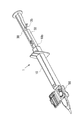
- FIG. 1 shows a schematic configuration of a conventional intraocular lens insertion device 1 (hereinafter also simply referred to as an insertion device 1).
- 1A is a plan view
- FIG. 1B is a side view.
- the insertion instrument 1 is formed in a cylindrical shape having a substantially rectangular cross section, and one side has a large opening (hereinafter, the side having the large opening is referred to as a rear end part 10b), and the insertion cylinder is narrowed to another one side end.
- the nozzle main body 10 as an instrument main body provided with the nozzle part 15 as a part and the front-end
- the direction from the front end portion 10a to the rear end portion 10b of the nozzle body 10 or the opposite direction is the front-rear direction
- the vertical direction to the paper surface in FIG. 1A is the vertical direction
- the paper surface in FIG. The vertical direction is the left-right direction.
- a stage portion 12 is provided as a storage portion for setting the intraocular lens 2.
- the stage portion 12 is configured such that the upper side of the nozzle body 10 (the front side perpendicular to the paper surface in FIG. 1A) is opened by opening the stage lid portion 13.
- a positioning member 50 is attached to the stage portion 12 from the lower side of the nozzle body 10 (the back side perpendicular to the paper surface in FIG. 1A). By this positioning member 50, the intraocular lens 2 is stably held in the stage portion 12 before use (during transportation).
- the intraocular lens 2 is set on the stage unit 12 in a state where the stage lid unit 13 is opened and the positioning member 50 is attached to the stage unit 12 at the time of manufacture. Then, after the stage lid 13 is closed, it is shipped and sold. Further, during use, the user removes the positioning member 50 while keeping the stage lid 13 closed, and then pushes the plunger 30 into the distal end side of the nozzle body 10. Thus, the intraocular lens 2 is pressed by the plunger 30, and the intraocular lens 2 is pushed out from the distal end portion 10a.
- the nozzle body 10, the plunger 30, and the positioning member 50 in the insertion instrument 1 are formed of a resin material such as polypropylene. Polypropylene is a material with a proven track record in medical equipment and high reliability such as chemical resistance.
- FIG. 2 is a diagram showing a schematic configuration of the intraocular lens 2.
- 2A is a plan view and FIG. 2B is a side view.
- the intraocular lens 2 is formed of a lens body 2a having a predetermined refractive power, and two beard-shaped support portions 2b, 2b that are provided on the lens body 2a and hold the lens body 2a in the eyeball. ing.
- the support portions 2b and 2b correspond to lens holding portions in this embodiment.
- the lens body 2a is made of a flexible resin material.
- FIG. 3 shows a plan view of the nozzle body 10.
- the intraocular lens 2 is set on the stage unit 12. In this state, the intraocular lens 2 is pushed out from the distal end portion 10a by being pressed by the plunger 30.
- a through hole 10 c whose cross-sectional shape changes according to a change in the outer shape of the nozzle body 10 is provided in the nozzle body 10.
- the intraocular lens 2 is pushed out, the intraocular lens 2 is deformed in accordance with a change in the cross-sectional shape of the through hole 10c in the nozzle body 10 and easily enters an incision formed in the patient's eyeball. It will be extruded after being transformed into.
- a stage groove 12 a having a width slightly larger than the diameter of the lens body 2 a of the intraocular lens 2 is formed in the stage portion 12.
- the dimension in the front-rear direction of the stage groove 12 a is set to be larger than the maximum width dimension including the support portions 2 b and 2 b extending on both sides of the intraocular lens 2.
- a set surface 12b is formed by the bottom surface of the stage groove 12a.
- the vertical position of the set surface 12b (the position perpendicular to the paper surface of FIG. 3) is set higher than the height position of the bottom surface of the through hole 10c of the nozzle body 10 (the front side perpendicular to the paper surface of FIG. 3).
- the set surface 12b and the bottom surface of the through hole 10c are connected by a bottom slope 10d.
- the stage portion 12 and the stage lid portion 13 are integrally formed.
- the stage lid portion 13 has the same size in the front-rear direction as the stage portion 12.
- the stage lid portion 13 is connected by a thin plate-like connecting portion 14 formed by extending the side surface of the stage portion 12 to the stage lid portion 13 side.
- the connecting portion 14 is formed to be bendable at the center portion, and the stage lid portion 13 can be closed by overlapping the stage portion 12 from above by bending the connecting portion 14.
- ribs 13 a and 13 b are provided on the surface facing the set surface 12 b when the lid is closed in order to reinforce the stage lid 13 and stabilize the position of the intraocular lens 2.
- a guide protrusion 13 c is provided as a guide on the upper side of the plunger 30.
- FIG. 4 shows a schematic configuration of the positioning member 50.
- 4A shows a plan view
- FIG. 4B shows a side view.
- the positioning member 50 is configured as a separate body from the nozzle main body 10, and has a structure in which a pair of side wall portions 51, 51 are connected by a connecting portion 52. At the lower ends of the respective side wall portions 51, holding portions 53, 53 extending outward and extending are formed.
- first mounting portions 54 and 54 are formed on the upper end portions of the respective side wall portions 51 and 51 so that the shape seen from above is an arc shape and protrudes upward.
- first positioning portions 55, 55 are formed to protrude from the outer peripheral side of the upper end surface of the first placement portion 54. The distance between the inner diameters of the first positioning portion 55 is set to be slightly larger than the diameter dimension of the lens body 2 a of the intraocular lens 1.
- a pair of second placement portions 56 and 56 are formed at both ends of the connecting portion 52 in the front-rear direction, and the shape seen from above is a rectangular shape and protrudes upward.
- the height of the upper surface of the second placement unit 56 is equal to the height of the upper surface of the first placement unit 54.
- second positioning portions 57 and 57 are formed on the outer surface of the second placement portions 56 and 56 so as to further protrude upward over the entire left and right direction of the second placement portion 56. .
- the separation between the insides of the second positioning portions 57 is set to be slightly larger than the diameter of the lens body 2a of the intraocular lens 2.
- locking claws 58 and 58 that slightly protrude in the front-rear direction are formed on the upper end portion of the second placement portion 56 over the entire left-right direction.
- the positioning member 50 is assembled from below the set surface 12b of the nozzle body 10.
- the set surface 12b of the nozzle body 10 is formed with a set surface through hole 12c that penetrates the set surface 12b in the thickness direction.
- the outer shape of the set surface through-hole 12c is a substantially similar shape that is slightly larger than the shape of the first placement portion 54 and the second placement portion 56 of the positioning member 50 as viewed from above.
- the positioning member 50 is assembled from the lower side of the nozzle body 10, and the first placement portions 54 and 54 and the second placement portions 56 and 56 are fixed in a state of protruding from the set surface 12b.
- the bottom surface of the outer peripheral portion of the lens body 2a is placed on the upper surfaces of the first placement portions 54 and 54 and the second placement portions 56 and 56.
- the position of the lens body 2 a is restricted with respect to the horizontal direction by the first positioning portions 55 and 55 and the second positioning portions 57 and 57.
- FIG. 5 shows a schematic configuration of the plunger 30.
- the plunger 30 has a length in the front-rear direction that is slightly larger than the nozzle body 10. And it forms from the action part 31 of the front end side based on a column shape, and the insertion part 32 of the rear end side based on a rectangular rod shape. And the action part 31 is comprised including the cylindrical part 31a made into the column shape, and the thin plate-shaped flat part 31b extended in the left-right direction of the cylindrical part 31a.
- a notch 31 c is formed at the tip of the action part 31.
- the notch 31 c is formed in a groove shape that opens upward in the action portion 31 and penetrates in the left-right direction.
- the groove wall on the distal end side of the cutout portion 31 c is formed with an inclined surface that goes upward as it goes to the distal end side of the action portion 31.
- the insertion part 32 has a substantially H-shaped cross section as a whole, and the horizontal and vertical dimensions thereof are set slightly smaller than the through hole 10c of the nozzle body 10.
- a disc-shaped pressing plate portion 33 is formed at the rear end of the insertion portion 32 so as to spread in the vertical and horizontal directions.
- a claw portion 32 a that protrudes toward the upper side of the insertion portion 32 and can be moved up and down by the elasticity of the material of the plunger 30 is formed at the tip side of the insertion portion 32 in the front-rear direction center.
- the locking hole 10 e shown in FIG. 3 provided in the thickness direction on the upper surface of the nozzle body 10 and the claw portion 32 a engage with each other.
- the relative position between the nozzle body 10 and the plunger 30 in the state is determined.
- the claw portion 32a and the locking hole 10e are formed at the positions where the tip of the action portion 31 is located behind the lens body 2a of the intraocular lens 2 set on the stage portion 12 in the engaged state. It is set so that the notch 31c can support the support part 2b on the rear side of 2a from below.
- the plunger 30 is inserted into the nozzle body 10 and disposed at the initial position. Further, as described above, the positioning member 50 is attached to the nozzle body 10 from below the set surface 12b. Thereby, the 1st mounting part 54 and the 2nd mounting part 56 of the positioning member 50 are hold
- the lens body 2a of the intraocular lens 2 is placed and positioned on the upper surfaces of the first placement part 54 and the second placement part 56 in a state where the support parts 2b and 2b are oriented in the front-rear direction of the nozzle body 10.
- the central portion of the intraocular lens 2 is supported in an unloaded state.
- the support portion 2 b of the intraocular lens 2 is supported by the groove portion 55 a provided in the first positioning portion 55 and the bottom surface of the notch portion 31 c of the plunger 30.
- the positioning member 50 When inserting the intraocular lens 2 into the eyeball using the insertion instrument 1, first, the positioning member 50 is removed from the nozzle body 10. Thereby, the 1st mounting part 54 and the 2nd mounting part 56 which were supporting the lens main body 2a of the intraocular lens 2 retreat from the set surface 12b, and the intraocular lens 2 can move on the set surface 12b. Placed.
- the distal end portion 10a of the nozzle portion 15 of the nozzle body 10 is inserted into the incision provided in the eye tissue.
- the distal end portion 10a has an oblique opening shape, it can be easily inserted into the incision.
- the press board part 33 of the plunger 30 is pushed in the front end side of the nozzle main body 10 in the state. Thereby, the front-end
- the tip of the nozzle body 10 There is a need to further reduce the size in the vicinity of 10a and reduce the diameter of the incision.
- the intraocular lens 2 is pressed by the plunger 30 and moved forward in the nozzle body 10
- the collapse rate of the intraocular lens 2 becomes higher, so that the intraocular lens 2 is removed from the distal end portion 10 a of the nozzle body 10.
- the plunger 30 protrudes excessively from the distal end portion 10a of the nozzle body 10. .
- the plunger 30 is provided with resistance increasing means for increasing the pushing resistance of the plunger 30 after the intraocular lens 2 jumps out of the distal end portion 10a.
- FIG. 6 shows a perspective view of the insertion instrument 1 in the present embodiment.
- a blade portion 35 formed by integral molding with the plunger 30 is provided on the side surface of the insertion portion 32 of the plunger 30.
- the blade portion 35 can be elastically deformed by utilizing the elasticity of the material of the plunger 30.
- the blade portion 35 is formed by extending the side surface of the insertion portion 32 on the rear side of the blade portion 35 in the insertion portion 32 in the lateral direction, and the angle of the coupling portion with the side surface of the insertion portion 32 is 90. It has an acute angle of less than 1 degree.
- the blade portion 35 is positioned behind the rear end portion 10b of the nozzle body 10 and is in contact with the nozzle body 10 in a state (initial state) before the insertion operation of the intraocular lens 2 is performed. Absent. In the operation of inserting the intraocular lens 2 into the eyeball, the blade part 35 is inserted into the nozzle body before and after the intraocular lens 2 is released from the tip 10a of the nozzle body 10 (immediately before, at the time of release, or after the release). 10 abuts against the rear end 10b. In this state, the tip of the plunger 30 does not protrude from the tip 10a. When the plunger 30 is further pushed in from this state, the push-in resistance of the plunger 30 increases sharply due to the deformation of the blade portion 35. *
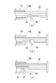
- FIG. 7 shows details of the action of the blade part 35 before and after the intraocular lens 2 is released from the tip part 10a of the nozzle body 10 in the operation of inserting the intraocular lens 2 into the eyeball.
- FIG. 7A shows a state in which the plunger 30 is pushed in by the user, but the blade portion 35 has not reached the rear end portion 10b.
- FIG. 7B shows a state in which the blade portion 35 is in contact with the side surface of the rear end portion 10b, and the plunger 30 is pushed in, whereby the blade portion 35 is deformed and its tilt angle is increased.
- FIG. 7C shows a state in which the plunger 30 is further pushed in after the deformation of the blade portion 35 is finished, and the blade portion 35 is sliding while contacting the inner wall of the through hole 10c.
- the state of FIG. 7A is a state before the intraocular lens 2 is released from the distal end portion 10a, and the pushing resistance of the plunger 30 increases due to the deformation of the intraocular lens 2.
- the part 35 does not contribute to the indentation resistance.
- the state of FIG. 7B is just before and after the time when the intraocular lens 2 is released from the distal end portion 10a. At this point, the pushing resistance caused by the intraocular lens 2 itself has weakened or disappeared. In this state, when the user pushes the plunger 30 into the nozzle body 10, the plunger 30 enters the nozzle body 10 while deforming the blade portion 35, so that the pushing resistance increases sharply. .
- the pushing resistance of the plunger 30 once increases sharply before and after the intraocular lens 2 is released into the eyeball from the tip portion 10a, and the intraocular lens 2 is moved into the eyeball from the tip portion 10a.
- the push-in resistance of the plunger 30 can be sufficiently increased at the time when it is released or after. And although it decreases a little after that, the state where pushing resistance is still high can be continued.
- the distal end of the plunger 30 protrudes vigorously from the distal end portion 10a, and inconveniences such as damaging the eyeball can be suppressed.
- the blade portion 35 as the resistance increasing means extends from the plunger 30 on the rear side of the blade portion 35, and the angle between the blade portion 35 and the insertion portion 32 of the plunger 30 is 90 degrees.
- FIG. 8 shows a variation of the structure of the blade portion.
- FIG. 8A shows the structure described in the first embodiment
- FIG. 8B shows a structure in which the blade portion 35 extends from the front side of the blade portion 35 in the insertion portion 32 of the plunger 30.
- the angle between the insertion portion 32 and the insertion portion 32 is an obtuse angle of 90 degrees or more.
- the blade portion 16 is provided on the nozzle body 10 side, and the pushing resistance of the plunger 30 is increased by contacting the amplifying portion 33 whose width increases in the insertion portion 32 of the plunger 30. It doesn't matter if you do.
- the example in which the blade portion 35 is formed integrally with the plunger 30 or the nozzle body 10 has been described. However, this is formed as a separate part, and bonding, screwing, and elasticity of the resin are used. You may fix to the plunger 30 or the nozzle body 10 by the fixed method etc. which were carried out. Further, the material of the blade portion 35 is not necessarily the same as that of the plunger 30 and the nozzle body 10 (for example, polypropylene), and may be a metal such as phosphor bronze, copper, or SUS.
- a raised portion 31e is provided on the rear side from a predetermined position of the action portion 31 of the plunger 30 so as to rise, and the through hole 10c has a structure.
- a contact portion 10g is provided on the front side of the raised portion 31e of the plunger 30 so as not to contact the action portion 31 of the plunger 30 but to contact the raised portion 31e.
- the contact portion 10g and the raised portion 31e of the plunger 30 constitute second resistance increasing means.
- FIG. 9 illustrates the plunger 30 in the present embodiment.
- the action part 31 of the plunger 30 is provided with a raised part 31e whose height in the upward direction is increased midway.
- a tapered slope 31f is provided on the leading end side of the raised portion 31e, and the raised height gradually increases as going backward.
- FIG. 10 shows a partial cross-sectional view of the nozzle body 10 in the present embodiment.
- a contact portion 10g having a wedge-shaped cross section is formed from the ceiling surface of the through hole 10c toward the lower side in the rear portion of the stage portion 12 of the ceiling surface of the through hole 10c. Yes.
- the tip height of the contact portion 10g is set so as not to contact the front side of the inclined surface 31f in the action portion 31 of the plunger 30, but to contact the raised portion 31e behind the inclined surface 31f.
- FIG. 11 explains the operation of the second resistance increasing means in the present embodiment.
- FIG. 11A shows a state before the raised portion 31e and the contact portion 10g come into contact with each other in a state where the user pushes the plunger 30.
- FIG. 11B shows a state in which the plunger 30 has moved further forward and the contact portion 10g has come into contact with the slope 31f of the raised portion 31e.
- FIG. 11C shows a state in which the plunger 30 further moves forward, and the contact portion 10g completely slides on the raised portion 31f while sliding.
- the slope 31f of the raised portion 31e and the contact portion 10g are positioned at positions such that the intraocular lens 2 starts to contact before the intraocular lens 2 is discharged from the tip portion 10a of the nozzle body 10. Is set. Thereby, the pushing resistance of the plunger 30 gradually increases from before the intraocular lens 2 is discharged into the eyeball, and then the state where the pushing resistance is high can be continued. As a result, when the user releases the intraocular lens 2 into the eyeball, the distal end of the plunger 30 can be gradually advanced, and the intraocular lens 2 can be prevented from jumping out from the distal end portion 10a.
- a raised portion 31e and a contact portion 10g are provided. Therefore, by these combinations, the pushing resistance of the plunger 30 before and after the intraocular lens 2 is ejected from the distal end portion 10a can be set with a higher degree of freedom.
- FIG. 12 shows the pushing resistance of the plunger 30 when the blade portion 35 which is the resistance increasing means in the present embodiment, the rising portion 31e and the contact portion 10g which are the second resistance increasing means are acted.
- the broken line indicates the pushing resistance in the conventional example without the blade portion 35, the raised portion 31e, and the contact portion 10g.
- D1 indicates the plunger push-in amount at which the intraocular lens 2 starts to come out from the tip portion 10a
- D2 indicates the plunger push-in amount when the intraocular lens 2 is released from the tip portion 10a.
- the amount of deformation of the intraocular lens 2 increases immediately before the intraocular lens 2 starts to come out from the distal end portion 10a.
- the resistance decreases.
- the intraocular lens 2 protrudes from the distal end portion 10a, and the plunger 30 protrudes vigorously from the distal end portion 10a.
- the plunger push-in resistance in this embodiment starts to increase sharply when the plunger push-in amount exceeds D1, and reaches a peak when the plunger push-in amount becomes D2. After that, the plunger pushing resistance slightly decreases, but changes so as to further increase.
- the plunger pushing resistance starts to increase sharply when the plunger pushing amount exceeds D1, which is an effect due to the contact between the rising portion 31e and the contact portion 10g.
- the plunger pushing resistance reaches a peak when the plunger pushing amount becomes D2, and is slightly reduced because of the effect that the blade portion 35 is deformed at that timing and then the sliding operation is started.
- the intraocular lens 2 is separated from the distal end portion 10a by combining the blade portion 35, the raised portion 31e, and the contact portion 10g, in other words, by combining the resistance increasing means and the second resistance increasing means.
- the plunger push-in resistance was sharply increased from before the release, and the plunger push-in resistance peaked at the timing when the intraocular lens 2 was released from the distal end portion 10a.
- the peak of the plunger push-in resistance is given at the timing when the intraocular lens 2 is released from the distal end portion 10a, but the present invention is not limited to this. The peak may be set slightly after the timing when the intraocular lens 2 is released from the distal end portion 10a.
- the raised portion 31e has a certain height behind the slope 31f.
- the plunger push-in resistance caused by the raised portion may be controlled by appropriately changing the height of the raised portion.
- FIG. 13 shows a variation example of the shape of the raised portion.
- FIG. 13A shows the rising portion 31e in the above embodiment.
- the height of the rising portion once reaches the peak behind the slope 31f, and then reaches a constant height after decreasing.
- the second resistance increasing means like the resistance increasing means, the pushing resistance of the plunger 30 is once increased sharply before and after the intraocular lens 2 is ejected from the distal end portion 10a, and then the pushing resistance is slightly increased. Control such as decreasing and continuing is possible.
- the user can move the plunger 30 when the intraocular lens 2 is released from the distal end portion 10a or after it is released. It is also possible to give a resistance accompanied by a click feeling when pushing further.
- a blade portion was used as the resistance increasing means, and a combination of the raised portion and the contact portion was used as the second resistance increasing means.
- the present invention is not limited to this combination.
- a resistance increasing means a raised portion is formed in a protruding shape as shown in FIG. 13 (b) at the insertion portion of the plunger, and a contact portion is also formed in a protruding shape on the inner wall of the nozzle body. May be used. According to this mechanism, the peak of the plunger push-in resistance can be generated at the timing when the protruding raised portion and the protruding contact portion come into contact with each other. Moreover, it is also possible to increase the indentation resistance after the peak by raising the back of the protruding raised portion of the plunger at a certain height.
- the resistance increasing means in the present invention is not limited to the one using elastic force or frictional resistance as described above.
- an oil damper is operated, an adhesive protrusion is brought into contact with the nozzle body, etc., thereby increasing resistance by using the viscosity or adhesive force of the substance. May be configured.
- a so-called preset system including a preset type insertion instrument in which an intraocular lens is loaded in advance on an intraocular lens insertion instrument
- the present invention is not limited to this, so that the intraocular lens insertion device and the intraocular lens are stored separately, and the so-called intraocular lens is loaded immediately before insertion into the eyeball. It can also be applied to a separate inserter.
- the intraocular lens to be inserted has been described as an example using a so-called three-piece type in which the lens body (optical part) and the support part are made of different materials, but the lens body (optical part)
- the present invention can also be applied to an insertion instrument for inserting a so-called one-piece intraocular lens in which the support part is integrally molded.
- the example of the material of the insertion device 1 is polypropylene, but the material of the insertion device 1 is not limited to this.
- the present invention can also be applied to an insertion device made of other materials.
Landscapes
- Health & Medical Sciences (AREA)
- Ophthalmology & Optometry (AREA)
- Cardiology (AREA)
- Oral & Maxillofacial Surgery (AREA)
- Transplantation (AREA)
- Engineering & Computer Science (AREA)
- Biomedical Technology (AREA)
- Heart & Thoracic Surgery (AREA)
- Vascular Medicine (AREA)
- Life Sciences & Earth Sciences (AREA)
- Animal Behavior & Ethology (AREA)
- General Health & Medical Sciences (AREA)
- Public Health (AREA)
- Veterinary Medicine (AREA)
- Prostheses (AREA)
Abstract
L'invention porte sur une technologie avec laquelle, après qu'une lentille intraoculaire ait été poussée à l'aide d'un instrument d'insertion, il est possible d'empêcher un piston de partir soudainement depuis une partie de tube d'insertion. La présente invention concerne un instrument d'insertion de lentille intraoculaire, dans laquelle une partie du tube d'insertion sur le corps principal d'instrument est insérée dans le globe oculaire à travers une incision formée dans le tissu oculaire et un piston est poussé dans le corps principal d'instrument afin de décharger une lentille intraoculaire déformable dans le globe oculaire à partir de la pointe de la partie de tube d'insertion insérée à l'intérieur de celui-ci. De plus, cet instrument est pourvu d'un moyen d'augmentation de résistance pour augmenter la résistance du piston dans le corps principal d'instrument au moment ou après le moment où la lentille intraoculaire est déchargée dans le globe oculaire depuis la pointe de la partie tube d'insertion.
Priority Applications (1)
| Application Number | Priority Date | Filing Date | Title |
|---|---|---|---|
| JP2014504908A JP6099628B2 (ja) | 2012-03-14 | 2013-03-11 | 眼内レンズの挿入器具 |
Applications Claiming Priority (2)
| Application Number | Priority Date | Filing Date | Title |
|---|---|---|---|
| JP2012-057539 | 2012-03-14 | ||
| JP2012057539 | 2012-03-14 |
Publications (1)
| Publication Number | Publication Date |
|---|---|
| WO2013137208A1 true WO2013137208A1 (fr) | 2013-09-19 |
Family
ID=49161115
Family Applications (1)
| Application Number | Title | Priority Date | Filing Date |
|---|---|---|---|
| PCT/JP2013/056689 Ceased WO2013137208A1 (fr) | 2012-03-14 | 2013-03-11 | Instrument d'insertion de lentille intraoculaire |
Country Status (2)
| Country | Link |
|---|---|
| JP (1) | JP6099628B2 (fr) |
| WO (1) | WO2013137208A1 (fr) |
Cited By (10)
| Publication number | Priority date | Publication date | Assignee | Title |
|---|---|---|---|---|
| WO2015076308A1 (fr) * | 2013-11-19 | 2015-05-28 | 興和株式会社 | Instrument d'insertion de lentille intraoculaire |
| JP2016083364A (ja) * | 2014-10-22 | 2016-05-19 | 参天製薬株式会社 | 眼内レンズ用インジェクタ |
| US9463089B2 (en) | 2012-05-21 | 2016-10-11 | Novartis Ag | Plunger system for intraocular lens surgery |
| JP2017000445A (ja) * | 2015-06-10 | 2017-01-05 | 興和株式会社 | 眼内レンズ挿入器具 |
| WO2017104690A1 (fr) | 2015-12-15 | 2017-06-22 | 参天製薬株式会社 | Porte-lentille et injecteur destiné à une lentille intraoculaire |
| US9757536B2 (en) | 2012-07-17 | 2017-09-12 | Novartis Ag | Soft tip cannula |
| US10568735B2 (en) | 2017-01-13 | 2020-02-25 | Alcon Inc. | Intraocular lens injector |
| US10588780B2 (en) | 2015-03-04 | 2020-03-17 | Alcon Inc. | Intraocular lens injector |
| US11000367B2 (en) | 2017-01-13 | 2021-05-11 | Alcon Inc. | Intraocular lens injector |
| JP2023128728A (ja) * | 2022-03-04 | 2023-09-14 | 株式会社ニデック | 眼内レンズ挿入器具 |
Families Citing this family (2)
| Publication number | Priority date | Publication date | Assignee | Title |
|---|---|---|---|---|
| RU2648229C1 (ru) | 2013-11-14 | 2018-03-22 | Эквисис, Инк. | Устройство для введения интраокулярного шунта |
| BR112020018242A2 (pt) * | 2018-03-09 | 2020-12-29 | Aquesys, Inc. | Insersor de shunt intraocular |
Citations (3)
| Publication number | Priority date | Publication date | Assignee | Title |
|---|---|---|---|---|
| WO2007097221A1 (fr) * | 2006-02-22 | 2007-08-30 | Hoya Corporation | outil d'insertion de cristallin artificiel |
| WO2007098622A1 (fr) * | 2006-02-28 | 2007-09-07 | Sdi Surgical Device International Gmbh | Injecteur de polarisation à ressort pour lentille intraoculaire |
| JP2009160151A (ja) * | 2007-12-28 | 2009-07-23 | Menicon Co Ltd | 眼内レンズの挿入器具 |
Family Cites Families (1)
| Publication number | Priority date | Publication date | Assignee | Title |
|---|---|---|---|---|
| JP5209332B2 (ja) * | 2008-02-04 | 2013-06-12 | 株式会社ニデック | 眼内レンズ挿入器具 |
-
2013
- 2013-03-11 WO PCT/JP2013/056689 patent/WO2013137208A1/fr not_active Ceased
- 2013-03-11 JP JP2014504908A patent/JP6099628B2/ja not_active Expired - Fee Related
Patent Citations (3)
| Publication number | Priority date | Publication date | Assignee | Title |
|---|---|---|---|---|
| WO2007097221A1 (fr) * | 2006-02-22 | 2007-08-30 | Hoya Corporation | outil d'insertion de cristallin artificiel |
| WO2007098622A1 (fr) * | 2006-02-28 | 2007-09-07 | Sdi Surgical Device International Gmbh | Injecteur de polarisation à ressort pour lentille intraoculaire |
| JP2009160151A (ja) * | 2007-12-28 | 2009-07-23 | Menicon Co Ltd | 眼内レンズの挿入器具 |
Cited By (13)
| Publication number | Priority date | Publication date | Assignee | Title |
|---|---|---|---|---|
| US9463089B2 (en) | 2012-05-21 | 2016-10-11 | Novartis Ag | Plunger system for intraocular lens surgery |
| US9757536B2 (en) | 2012-07-17 | 2017-09-12 | Novartis Ag | Soft tip cannula |
| WO2015076308A1 (fr) * | 2013-11-19 | 2015-05-28 | 興和株式会社 | Instrument d'insertion de lentille intraoculaire |
| JPWO2015076308A1 (ja) * | 2013-11-19 | 2017-03-16 | 興和株式会社 | 眼内レンズの挿入器具 |
| US10195019B2 (en) | 2013-11-19 | 2019-02-05 | Kowa Company, Ltd. | Intraocular lens insertion apparatus |
| JP2016083364A (ja) * | 2014-10-22 | 2016-05-19 | 参天製薬株式会社 | 眼内レンズ用インジェクタ |
| US10588780B2 (en) | 2015-03-04 | 2020-03-17 | Alcon Inc. | Intraocular lens injector |
| JP2017000445A (ja) * | 2015-06-10 | 2017-01-05 | 興和株式会社 | 眼内レンズ挿入器具 |
| WO2017104690A1 (fr) | 2015-12-15 | 2017-06-22 | 参天製薬株式会社 | Porte-lentille et injecteur destiné à une lentille intraoculaire |
| US10568735B2 (en) | 2017-01-13 | 2020-02-25 | Alcon Inc. | Intraocular lens injector |
| US11000367B2 (en) | 2017-01-13 | 2021-05-11 | Alcon Inc. | Intraocular lens injector |
| JP2023128728A (ja) * | 2022-03-04 | 2023-09-14 | 株式会社ニデック | 眼内レンズ挿入器具 |
| JP7753927B2 (ja) | 2022-03-04 | 2025-10-15 | 株式会社ニデック | 眼内レンズ挿入器具 |
Also Published As
| Publication number | Publication date |
|---|---|
| JP6099628B2 (ja) | 2017-03-22 |
| JPWO2013137208A1 (ja) | 2015-08-03 |
Similar Documents
| Publication | Publication Date | Title |
|---|---|---|
| JP6099628B2 (ja) | 眼内レンズの挿入器具 | |
| JP6258865B2 (ja) | 眼内レンズの挿入器具 | |
| US11938019B2 (en) | Intraocular lens insertion device | |
| JP5255832B2 (ja) | 眼内レンズの挿入器具 | |
| CN105636552B (zh) | 人工晶状体的插入仪器 | |
| JP5697962B2 (ja) | 眼内レンズの挿入器具 | |
| JP5836282B2 (ja) | 眼内レンズの挿入器具 | |
| JP4877643B2 (ja) | 眼内レンズ挿入用器具 | |
| WO2016195095A1 (fr) | Outil d'insertion de lentille intraoculaire | |
| JP2008012016A (ja) | 眼内レンズ挿入用器具 | |
| JP2013244186A (ja) | 眼内レンズの挿入器具 | |
| JP6627267B2 (ja) | 眼内レンズ挿入器具 | |
| JP4557938B2 (ja) | 眼内レンズの挿入器具 | |
| CN111050698A (zh) | 眼内透镜插入器具 | |
| JP6575761B2 (ja) | 眼内レンズの挿入器具 | |
| JP2018198747A (ja) | 眼内レンズおよび眼内レンズ挿入器具 | |
| JP5096132B2 (ja) | 眼内レンズの挿入器具 | |
| WO2017030139A1 (fr) | Instrument d'insertion de lentille intraoculaire | |
| HK40027078A (en) | Intraocular lens insertion instrument | |
| HK1224543B (en) | Intraocular lens-inserting instrument | |
| HK1224543A1 (en) | Intraocular lens-inserting instrument |
Legal Events
| Date | Code | Title | Description |
|---|---|---|---|
| 121 | Ep: the epo has been informed by wipo that ep was designated in this application |
Ref document number: 13761592 Country of ref document: EP Kind code of ref document: A1 |
|
| DPE1 | Request for preliminary examination filed after expiration of 19th month from priority date (pct application filed from 20040101) | ||
| ENP | Entry into the national phase |
Ref document number: 2014504908 Country of ref document: JP Kind code of ref document: A |
|
| NENP | Non-entry into the national phase |
Ref country code: DE |
|
| 122 | Ep: pct application non-entry in european phase |
Ref document number: 13761592 Country of ref document: EP Kind code of ref document: A1 |