WO2013137253A1 - 電流センサ、センサ素子および制御装置 - Google Patents
電流センサ、センサ素子および制御装置 Download PDFInfo
- Publication number
- WO2013137253A1 WO2013137253A1 PCT/JP2013/056812 JP2013056812W WO2013137253A1 WO 2013137253 A1 WO2013137253 A1 WO 2013137253A1 JP 2013056812 W JP2013056812 W JP 2013056812W WO 2013137253 A1 WO2013137253 A1 WO 2013137253A1
- Authority
- WO
- WIPO (PCT)
- Prior art keywords
- signal
- coil
- detection
- cancel
- component
- Prior art date
- Legal status (The legal status is an assumption and is not a legal conclusion. Google has not performed a legal analysis and makes no representation as to the accuracy of the status listed.)
- Ceased
Links
Images




Classifications
-
- G—PHYSICS
- G01—MEASURING; TESTING
- G01R—MEASURING ELECTRIC VARIABLES; MEASURING MAGNETIC VARIABLES
- G01R19/00—Arrangements for measuring currents or voltages or for indicating presence or sign thereof
- G01R19/0092—Measuring current only
-
- G—PHYSICS
- G01—MEASURING; TESTING
- G01R—MEASURING ELECTRIC VARIABLES; MEASURING MAGNETIC VARIABLES
- G01R15/00—Details of measuring arrangements of the types provided for in groups G01R17/00 - G01R29/00, G01R33/00 - G01R33/26 or G01R35/00
- G01R15/14—Adaptations providing voltage or current isolation, e.g. for high-voltage or high-current networks
- G01R15/18—Adaptations providing voltage or current isolation, e.g. for high-voltage or high-current networks using inductive devices, e.g. transformers
- G01R15/183—Adaptations providing voltage or current isolation, e.g. for high-voltage or high-current networks using inductive devices, e.g. transformers using transformers with a magnetic core
- G01R15/185—Adaptations providing voltage or current isolation, e.g. for high-voltage or high-current networks using inductive devices, e.g. transformers using transformers with a magnetic core with compensation or feedback windings or interacting coils, e.g. 0-flux sensors
-
- G—PHYSICS
- G01—MEASURING; TESTING
- G01R—MEASURING ELECTRIC VARIABLES; MEASURING MAGNETIC VARIABLES
- G01R33/00—Arrangements or instruments for measuring magnetic variables
- G01R33/02—Measuring direction or magnitude of magnetic fields or magnetic flux
Definitions
- the present invention relates to a current sensor that detects a current flowing through a detected electric wire.
- the signal level detected on the detection coil side that receives the excitation signal is the signal level of the detected current that penetrates the annular region of the core member. Therefore, it is common to specify (detect) the detected current based on the change (see Patent Document 1).
- the current sensor having the above configuration saturates the core member to the vicinity of the saturation magnetization density Bs by the detected current, thereby distorting the magnetic flux B generated as a sine wave by the excitation signal and applying a signal level corresponding to the change. Since the detection current signal level is specified, only a narrow current range corresponding to the vicinity of the saturation magnetization density Bs can be detected.
- 1st aspect of this invention is a current sensor containing a sensor element and a detection part, Comprising:
- the said sensor element forms the magnetic material in cyclic
- annular form The magnetic permeability ⁇ decreases with the external magnetic field 0 as the apex according to the external magnetic field that changes due to the influence of the signal, and the change in the magnetic permeability ⁇ is plotted in the “coordinate system defined by the external magnetic field ⁇ permeability ⁇ ”.
- the detection unit extracts, from the output signal of the detection coil, a component extraction unit that extracts a harmonic component superimposed on the fundamental wave component from signal components included in the output signal, and the output signal Corresponding to the harmonic component extracted by the component extraction unit, based on the correspondence relationship in which the harmonic component that can be included and the signal level of the detected signal when the harmonic component is generated are associated with each other
- a level specifying unit that specifies the signal level as the signal level of the detected signal at that time; and an information output unit that outputs information indicating the signal level specified by the level specifying unit to the outside.
- a magnetic flux corresponding to the signal level of the signal to be detected is superimposed on the core member.
- the curvature of the ⁇ -H curve defined by the external magnetic field H and the magnetic permeability ⁇ increases according to the magnitude of the absolute value in the external magnetic field H.
- the ⁇ -H coordinate is along the x-axis at an arbitrary position on the quadratic curve.
- the harmonic component corresponding to the “bending” of the quadratic curve is superimposed on the output signal from the detection coil whose amplitude changes along the y-axis.
- the electric wire is connected to the core member in order to improve the signal level of the detected current.
- the current sensor can be simplified and downsized, its application is wide.
- the specific configuration for extracting the harmonic component from the detection signal is not particularly limited.
- the core member includes first and second core members disposed along a direction penetrating the detection region
- the exciting coil includes the first and second core members. Two wound around each of the two core members are connected in series, and the number of windings and the positional relationship are determined so that the signal flowing in one and the signal flowing in the other have opposite phase and the same signal level.
- the detection coil is wound so that the two wound around the first and second core members are connected in series, and the signal flowing in one and the signal flowing in the other have the same phase and the same signal level. The number of times and the positional relationship are determined.
- the component extraction unit extracts the output signal itself from the detection coils connected in series as the harmonic component.
- each excitation coil is connected in series with opposite phases, and each detection coil is connected in series with the same phase. Therefore, a fundamental wave component (an AC signal such as a sine wave) that regularly increases or decreases from the magnetic flux generated by the excitation signal. Component, the same applies below), while harmonic components that increase or decrease irregularly as distortion are emphasized and output.
- a fundamental wave component an AC signal such as a sine wave
- the core member includes first and second core members arranged along a direction penetrating the detection region, and the excitation coil includes the first coil. , The number of windings and the positional relationship are determined so that the two wound around each of the second core members are connected in series, and the signal flowing in one and the signal flowing in the other have the opposite phase and the same signal level.
- the detection coil is a single coil wound around the first and second core members.
- the component extraction unit extracts the output signal itself from the detection coil as the harmonic component.
- the exciting coils are connected in series with opposite phases, and the detection coil is wound around the first and second core members with the core including the first and second core members as one core member.
- the fundamental wave component that regularly increases and decreases from the magnetic flux generated by the excitation signal is canceled out, while the harmonic component that irregularly increases and decreases as distortion is emphasized and output.
- the sensor element is provided with a displacement generation unit that generates a displacement signal obtained by shifting the phase of the output signal by 1 ⁇ 2 period based on the output signal of the detection coil.
- the component extraction unit extracts a signal obtained by superimposing the output signal from the detection coil and the displacement signal generated by the displacement generation unit as the harmonic component.
- the signal in which the harmonic component is emphasized can be extracted, and the signal level of the detected signal can be specified therefrom.
- the harmonic component since the harmonic component is emphasized and outputted, the correspondence between the harmonic component and the signal level of the detected signal is based on the emphasized harmonic component. Will be prepared.
- the magnetic permeability ⁇ in the core member may fluctuate not only due to the influence of the external magnetic field but also due to the influence of the temperature environment. Therefore, it is desirable to suppress the unintended fluctuation of the harmonic component accompanying the fluctuation of the magnetic permeability and to make it less susceptible to the influence of the temperature environment in order to increase the accuracy as the current sensor in this configuration.
- the sensor element includes a cancel coil wound around the core member and energized with a cancel signal for canceling a change in the external magnetic field due to the influence of the detected signal.
- the harmonic component superimposed on the output signal from the detection coil is changed by changing the external magnetic field due to the influence of the cancel signal supplied to the cancel coil.
- the said detection part is provided with the cancellation control part which controls electricity supply of the cancellation signal to the said cancellation coil
- the said cancellation control part is such that the harmonic component extracted by the said component extraction part becomes small
- Feedback control is performed on the signal level of the cancellation signal
- the level specifying unit determines that the harmonic component extracted by the component extraction unit is less than a predetermined threshold after feedback control by the cancellation control unit is started.
- the signal level of the cancel signal is the signal level of the cancel signal that triggered the harmonic component to be less than the threshold value.
- a signal level corresponding to Le is specified as signal level of the signal to be detected at that point.
- the change in the external magnetic field due to the detected signal is canceled by feedback control of the cancellation signal, and the signal level of the detected signal is specified based on the signal component of the canceled signal thus canceled.
- the cancel signal is output from the cancel coil wound around the same core member as the detection coil, and is affected by the same external magnetic field and temperature environment as the output signal from the detection coil. Therefore, changing the signal level of the cancel signal to cancel the change in the external magnetic field due to the detected signal means that the signal level corresponding to the signal level of the detected signal is reproduced by the cancel signal, This means that the signal level of the cancel signal corresponds to the signal level of the detected signal.
- the signal level of the detected signal can be specified based on the signal component of the canceled signal thus canceled.
- the cancel coil may be wound around the core member.
- the exciting coil includes two coils wound around the first and second core members connected in series, and a signal flowing in one and a signal flowing in the other are in reverse phase and The number of windings and the positional relationship are determined so that the same signal level is obtained, and two of the detection coils wound around each of the first and second core members are connected in series and flow to one side. The number of windings and the positional relationship are determined so that the signal and the signal flowing on the other side have the same phase and the same signal level.
- the component extraction unit extracts the output signal itself from the detection coils connected in series as the harmonic component. Furthermore, in the sensor element, two cancel coils are wound around the first and second core members in series, and a signal flowing in one and a signal flowing in the other have the same phase and the same signal level. Thus, the number of windings and the positional relationship are determined.
- the excitation coil includes two coils wound around the first and second core members connected in series, and a signal flowing in one and a signal flowing in the other are reversed.
- the number of windings and the positional relationship are determined so that the phase and the same signal level are obtained, and two of the detection coils wound around each of the first and second core members are connected in series, The number of windings and the positional relationship are determined so that the signal flowing to the other and the signal flowing to the other have the same phase and the same signal level.
- the component extraction unit extracts the output signal itself from the detection coils connected in series as the harmonic component.
- the cancel coil is one coil that is wound around the first and second core members together.
- the eighth aspect in the sensor element, two of the exciting coils wound around the first and second core members are connected in series, and a signal flowing in one and a signal flowing in the other are reversed.
- the number of windings and the positional relationship are determined so that the phase and the signal level are the same, and the detection coil is a single coil that is wound around the first and second core members. is there.
- the component extraction unit extracts the output signal itself from the detection coils connected in series as the harmonic component.
- two cancel coils are wound around the first and second core members in series, and a signal flowing in one and a signal flowing in the other have the same phase and the same signal level.
- the number of windings and the positional relationship are determined.
- the detection coil is a single coil that is wound around the first and second core members. is there.
- the component extraction unit extracts the output signal itself from the detection coils connected in series as the harmonic component.
- the cancel coil is one coil that is wound around the first and second core members together.
- the sensor element according to the tenth aspect is formed of a magnetic material in an annular shape, and responds to an external magnetic field that changes due to the influence of a signal to be detected that penetrates the detection region surrounded by the annular shape.
- the magnetic permeability ⁇ decreases at the apex of the external magnetic field 0, and the curvature of the curve when the change in the magnetic permeability ⁇ is plotted in the “coordinate system defined by the external magnetic field ⁇ the magnetic permeability ⁇ ” is A core member having a characteristic of increasing in accordance with an absolute value, an excitation coil wound around the core member to excite the core member, wound around the core member, and used for detecting the detected signal When the detected signal flows in a state where an excitation signal consisting of a fundamental wave component is energized to the excitation coil, a harmonic component corresponding to the magnetic permeability ⁇ of the core member at that time is provided. Basic wave generation Signal superimposed on is configured so as to be outputted from the detection coil.
- the sensor element includes a cancel coil wound around the core member and energized with a cancel signal for canceling a change in the external magnetic field due to the influence of the detected signal.
- the eleventh aspect (Claim 11) is adopted in which the harmonic component superimposed on the output signal from the detection coil changes due to the change of the external magnetic field due to the influence of the cancel signal energized to the coil. Good.
- a control device is a control device connected to the sensor element according to any one of the first to ninth configurations, and from the output signal of the detection coil, Among the signal components included in the output signal, a component extraction unit that extracts a harmonic component superimposed on the fundamental wave component, a harmonic component that can be included in the output signal, and the harmonic component are generated
- the signal level corresponding to the harmonic component extracted by the component extraction unit is set as the signal level of the detected signal at that time based on the correspondence relationship in which the signal level of the detected signal is associated with A level specifying unit for specifying; and an information output unit for outputting information indicating the signal level specified by the level specifying unit to the outside.
- the sensor element includes a cancel coil that is wound around the core member and is energized with a cancel signal for canceling a change in the external magnetic field due to the influence of the detected signal.
- the harmonic component superimposed on the output signal from the detection coil is changed. It is good to do so.
- a cancel control unit that controls energization of a cancel signal to the cancel coil
- the cancel control unit is configured to reduce the harmonic signal extracted by the component extraction unit.
- FIG. 2A is a graph showing the characteristics of the core member (MH curve defined by change in magnetization M with respect to external magnetic field H).
- FIG. 2B is a graph showing the characteristics of the core member (MH curve defined by change in magnetization M with respect to external magnetic field H; an enlarged view of the low magnetic field region in FIG. 2A).
- FIG. 2C is a graph ( ⁇ -H curve defined by the external magnetic field H and the magnetic permeability ⁇ ) showing the characteristics of the core member.
- FIG. 2D is a graph showing the characteristics of the core member ( ⁇ -H curve defined by the external magnetic field H and the magnetic permeability ⁇ ; an enlarged view of the low magnetic field region in FIG.
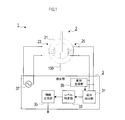
- the sensor element 2 has a core member 21 formed of a magnetic material in an annular shape, an excitation coil 23 that is wound around the core member 21 and excites the core member 21, and is wound around the core member 21 to be detected. And a detection coil 25 used for signal detection.
- the core member 21 responds to an external magnetic field that changes due to the influence of the detected signal when the detected electric wire 100 is passed through the detection region surrounded by the ring and the detected signal is conducted there.
- the magnetic permeability ⁇ decreases with the external magnetic field 0 as the apex.
- the permeability ⁇ is the slope of the MH curve (see FIGS. 2A and 2B) defined by the change of the magnetization M with respect to the external magnetic field H (that is, the differentiation of the magnetization M with respect to the magnetic field H, as shown in the following formula 1. Value) based on (value).
- the magnetic member described in Japanese Patent Application No. 2010-215871 filed by the applicant of the present application may be adopted.
- the detection coil 25 is configured to output a signal obtained by superimposing a harmonic component corresponding to the fundamental wave component.
- the detection unit 3 is a control device that inputs and outputs various signals in order to specify the signal level of the detected signal based on the output signal from the sensor element 2 (the detection coil 25).
- the component extraction unit 31 that extracts the harmonic component superimposed on the fundamental wave component, and the signal level corresponding to the harmonic component extracted by the component extraction unit 31 at that time point
- a level specifying unit 33 for specifying the signal level of the detected signal
- an information output unit 35 for outputting information indicating the signal level specified by the level specifying unit 33 to the outside
- a signal source for energizing the excitation coil 23 37.
- the level specifying unit 33 detects the detected signal based on the correspondence relationship that associates the harmonic component that can be included in the output signal and the signal level of the detected signal when the harmonic component is generated. Identify the signal level of the signal.
- the signal source 37 energizes the exciting coil 23 by an AC signal (in this embodiment, a sine wave signal), and the AC component in this signal becomes a fundamental wave component via the core member 21 and is detected by the detection coil 25. Will be.
- an AC signal in this embodiment, a sine wave signal
- the detection unit 3 is provided with a displacement generation unit 39 that generates a displacement signal obtained by shifting the phase of the output signal by 1 ⁇ 2 period based on the output signal of the detection coil 25, and extracts components.
- the unit 31 extracts a signal obtained by superimposing the output signal from the detection coil 25 and the displacement signal generated by the displacement generation unit 39 as a harmonic component.
- the displacement generation unit 39 may be configured to generate a displacement signal by data processing after converting the output signal into a digital signal, or to generate a displacement signal that is shifted by a half cycle by a delay circuit. It is good also as composition to do.
- the current sensor 1 according to the present embodiment includes two core members 21 arranged so that the same detected electric wire 100 flows in each detection region, and the core The difference from the first embodiment is that the exciting coil 23 and the detection coil 25 are wound around each member 21 and that the displacement generating unit 39 is not provided.
- the exciting coils 23 are connected in series, and are wound so that the signal flowing through one exciting coil 23 and the signal flowing through the other exciting coil 23 have opposite phases and the same signal level. Number of times and positional relationship.
- Each of the detection coils 25 is connected in series, and the number of times that the signal flowing in one detection coil 25 and the signal flowing in the other detection coil 25 are wound so that they have the same phase and the same signal level. It is a positional relationship.
- the component extraction part 31 of the detection part 3 is comprised so that the output signal itself from the detection coil 25 connected in series may be extracted as a harmonic component.
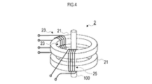
- the detection coil 25 uses the core composed of the first and second core members 21 as one core member, and combines them into the first and second core members 21. It may be wound around.
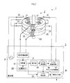
- the current sensor 1 in the present embodiment includes a cancel coil 51 wound around the sensor element 2, and the detection unit 3 includes a cancel control unit 60. Since the configuration differs from the other embodiments, this difference will be described in detail.
- the cancel coil 51 in the sensor element 2 is wound around the core member 21, and a cancel signal for canceling a change in the external magnetic field due to the influence of the detected signal is energized.
- the sensor element 2 is configured to change the harmonic component superimposed on the signal output from the detection coil 25 by changing the external magnetic field under the influence of the cancel signal energized to the cancel coil 51. ing.
- the cancel control unit 60 of the detection unit 3 controls the energization of the cancel signal to the cancel coil 51, and feedback controls the signal level of the cancel signal so that the harmonic component extracted by the component extraction unit 31 is reduced. Is configured to do.
- the cancel control unit 60 compares the harmonic component (the signal level) detected by the component extraction unit 31 with a target value (“0” in the present embodiment) stored in advance in the memory, and outputs the deviation. 61, an integrator 63 that integrates the deviation output to the comparator 61 and outputs the integrated value, a level calculator 65 that calculates the signal level of the cancel signal based on the integrated value output to the integrator 63, A level control circuit 67 is provided for energizing a cancel signal to the cancel coil 51 and controlling the signal level according to the calculation result of the level calculator 65.
- the level calculator 65 calculates a signal level that is increased or decreased by a certain value as a signal level of the cancel signal based on the sign of the integrated value output from the integrator 63.
- the signal level of the cancel signal necessary for setting the integral value from the calculator 63 to “0” may be directly calculated.
- the level specifying unit 33 of the detection unit 3 checks the output of the comparator 61 in the cancel control unit 60, and the deviation output to the comparator 61 is less than a predetermined threshold (for example, “ 0 ”), that is, when it is determined that the harmonic component matches the target value, the signal level of the cancel signal that triggers the harmonic component to fall below the threshold value is acquired from the level calculator 65. Based on this, the signal level of the detected signal at that time is specified.
- a predetermined threshold for example, “ 0 ”
- a correspondence relationship that correlates the harmonic component that is canceled according to the signal level of the cancel signal and the signal level of the detected signal when the harmonic component is generated.
- the signal level corresponding to the signal level of the cancel signal that triggered the harmonic component to be less than the threshold is specified as the signal level of the detected signal at that time.
- the signal level of the cancel signal that triggered the harmonic component to be less than the threshold value is calculated by the level calculator 65 based on the integral value “0” from the calculator 63.
- the level specifying unit 33 checks the calculation value of the level calculator 65 to acquire the calculation value as the corresponding signal level.
- the calculation value by the level calculator 65 is configured to be stored in time series, and the calculation value used for the calculation when the harmonic component is less than the threshold value is acquired as the corresponding signal level. It is good to do.
- the processing and calculation by the detection unit 3 are configured to be realized by a hardware configuration.
- these processes and operations may be realized by a software program and a microcomputer that executes the software program.
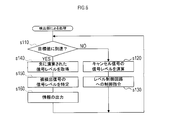
- the detection unit 3 having a function as a microcomputer to execute a software program as shown below (see FIG. 6).
- the program may be stored in the memory of the detection unit 3 in advance, but may be provided to the user in a state of being recorded on various recording media or distributed to the user of the current sensor 1 via the network. Good.
- the detector 3 checks whether or not the output value from the component extraction unit 31 has reached a target value (a value less than a threshold value centered on the target value) (s110). Is not reached (s110: NO), the same calculation as that of the level calculator 65 is performed based on the target value (s120), and a control command is issued to the level control circuit 67 based on the calculated value (s130). ), And so on.
- a target value a value less than a threshold value centered on the target value
- the current sensor 1 is mainly composed of first and second core members 21 arranged along the direction in which the core members penetrate the detection regions, respectively, as shown in FIG. Since the configuration is different from the third embodiment in that the displacement generation unit 39 is not provided, this difference will be mainly described in detail.
- the two exciting coils 23 in the sensor element 2 wound around the first and second core members 21 are connected in series so that the signal flowing in one and the signal flowing in the other have opposite phases and the same signal level.
- the number of windings and the positional relationship are defined.
- the detection coil 25 is wound so that two wound around the first and second core members 21 are connected in series so that the signal flowing in one and the signal flowing in the other have the same phase and the same signal level. The number of rotations and the positional relationship are determined.
- the cancel coil 51 is wound in such a way that two wound around the first and second core members 21 are connected in series so that the signal flowing in one and the signal flowing in the other have the same phase and the same signal level. The number of rotations and the positional relationship are determined.
- the component extraction part 31 is comprised so that the output signal itself from the detection coil 25 connected in series may be extracted as a harmonic component.
- the detection coil 25 uses the core composed of the first and second core members 21 as one core member, and combines them into the first and second core members 21. It may be wound around.
- the cancel coil 51 is wound around the first and second core members 21 by using the core composed of the first and second core members 21 as one core member. It may be a thing. Further, in this case, as shown in FIG. 8C, the detection coil 25 may be wound around the first and second core members 21 together.
- a fundamental wave component that regularly increases or decreases from the signal component of the output signal is obtained by canceling the output signal itself and the displacement signal obtained by shifting the phase of the output signal by 1 ⁇ 2 period.
- a signal is extracted in which harmonic components that increase or decrease irregularly as distortion are emphasized. Thereby, the signal in which the harmonic component is emphasized can be extracted, and the signal level of the detected signal can be specified therefrom.
- the harmonic component is emphasized and output in this way, so a correspondence relationship with the signal level of the detected signal is prepared based on the emphasized harmonic component. It will be.
- the excitation coils 23 are connected in series with opposite phases, and the detection coils 25 are connected in series with the same phase. While the wave component is canceled out, the harmonic component that irregularly increases or decreases as distortion is emphasized and output.
- the exciting coils 23 are connected in series in opposite phases, and the detection coil 25 is the first and second core members 21 with the core formed by the first and second core members 21 as one core member. The same applies to the case where the components are wound together.
- the output signal itself from the set of detection coils 25 connected in series can be extracted as a harmonic component, and the signal level of the detected signal can be specified therefrom.
- the harmonic component is emphasized and output in this way, so a correspondence relationship with the signal level of the detected signal is prepared based on the emphasized harmonic component. It will be.
- the external magnetic field can be changed by the cancel signal via the first and second core members 21. Moreover, in these current sensors 1, the change in the external magnetic field due to the detected signal is canceled by feedback control of the cancellation signal, and the signal level of the detected signal is specified based on the signal component of the canceled signal thus canceled. ing.
- the cancel signal is output from the cancel coil wound around the same core member as the detection coil, and is affected by the same external magnetic field and temperature environment as the output signal from the detection coil. Therefore, changing the signal level of the cancel signal to cancel the change in the external magnetic field due to the detected signal means that the signal level corresponding to the signal level of the detected signal is reproduced by the cancel signal, This means that the signal level of the cancel signal corresponds to the signal level of the detected signal.
- the signal level of the detected signal can be specified based on the signal component of the canceled signal thus canceled.
Landscapes
- Physics & Mathematics (AREA)
- General Physics & Mathematics (AREA)
- Engineering & Computer Science (AREA)
- Power Engineering (AREA)
- Condensed Matter Physics & Semiconductors (AREA)
- Measuring Magnetic Variables (AREA)
- Measuring Instrument Details And Bridges, And Automatic Balancing Devices (AREA)
- Measurement Of Current Or Voltage (AREA)
- Transformers For Measuring Instruments (AREA)
Abstract
Description
第2局面のうち、前記センサ素子において、前記コア部材は、それぞれ前記検出領域を貫通する方向に沿って配置された第1,第2コア部材からなり、前記励磁コイルは、前記第1,第2コア部材それぞれに巻回された2つが直列接続され、一方に流れる信号と他方に流れる信号とが逆位相かつ同一信号レベルとなるように、巻回される回数および位置関係が定められており、前記検出コイルは、前記第1,第2コア部材それぞれに巻回された2つが直列接続され、一方に流れる信号と他方に流れる信号とが同位相かつ同一信号レベルとなるように、巻回される回数および位置関係が定められている。そして、前記検出部において、前記成分抽出部は、直列接続された前記検出コイルからの出力信号そのものを前記高調波成分として抽出する。
また、第3局面のうち、前記センサ素子において、前記コア部材は、それぞれ前記検出領域を貫通する方向に沿って配置された第1,第2コア部材からなり、前記励磁コイルは、前記第1,第2コア部材それぞれに巻回された2つが直列接続され、一方に流れる信号と他方に流れる信号とが逆位相かつ同一信号レベルとなるように、巻回される回数および位置関係が定められており、前記検出コイルは、前記第1,第2コア部材へとまとめて巻回されてなる1つのコイルである。そして、前記検出部において、前記成分抽出部は、前記検出コイルからの出力信号そのものを前記高調波成分として抽出する。
そして、第4局面のうち、前記センサ素子において、前記検出コイルの出力信号に基づいて、該出力信号の位相を1/2周期ズラしてなる変位信号を生成する変位生成部、が備えられており、前記検出部において、前記成分抽出部は、前記検出コイルからの出力信号と、前記変位生成部により生成された変位信号と、を重畳してなる信号を前記高調波成分として抽出する。
なお、上記第2~第4局面においては、高調波成分が強調されて出力されることから、その強調された高調波成分に基づいて、高調波成分と被検出信号の信号レベルとの対応関係を用意しておくことになる。
また、上記課題を解決するため第10局面に係るセンサ素子は、磁性材料を環状に形成してなり、該環状に囲まれた検出領域を貫通する被検出信号の影響で変化する外部磁場に応じて外部磁場0を頂点に透磁率μが減少していくと共に、該透磁率μの変化を「外部磁場-透磁率μで規定される座標系」にプロットした場合における曲線の曲率が外部磁場の絶対値に応じて大きくなる、といった特性を有するコア部材と、前記コア部材に巻回され、該コア部材を励磁する励磁コイルと、前記コア部材に巻回され、前記被検出信号の検出に用いられる検出コイルと、を備え、前記励磁コイルに基本波成分からなる励磁信号を通電した状態で、前記被検出信号が流れると、その時点における前記コア部材の透磁率μに応じた高調波成分が前記基本波成分に重畳された信号が、前記検出コイルから出力されるように構成されている。
この局面のうち、前記センサ素子においては、前記コア部材に巻回され、前記被検出信号の影響による外部磁場の変化を相殺させるためのキャンセル信号が通電されるキャンセルコイル、が備えられ、前記キャンセルコイルに通電されるキャンセル信号の影響で外部磁場が変化することにより、前記検出コイルからの出力信号に重畳された高調波成分が変化する、といった第11局面(請求項11)を採用してもよい。
この局面のうち、前記センサ素子が、前記コア部材に巻回され、前記被検出信号の影響による外部磁場の変化を相殺させるためのキャンセル信号が通電されるキャンセルコイル、を備え、前記キャンセルコイルに通電されるキャンセル信号の影響で外部磁場が変化することにより、前記検出コイルからの出力信号に重畳された高調波成分を変化させるように構成されている場合には、以下に示す第13局面のようにするとよい。
(1)第1実施形態
本実施形態における電流センサ1は、図1に示すように、センサ素子2と検出部3とを備える。

(2)第2実施形態
本実施形態における電流センサ1は、図3に示すように、同一の被検出電線100がそれぞれの検出領域に流れるように配置された2つのコア部材21を備え、コア部材21それぞれに励磁コイル23および検出コイル25が巻回されていること、および、変位生成部39が備えられていないこと、が第1実施形態との相違点となっている。
なお、この実施形態において、検出コイル25は、図4に示すように、第1,第2コア部材21で構成されるコアを一つのコア部材として、これら第1,第2コア部材21にまとめて巻回されたものとしてもよい。
(3)第3実施形態
本実施形態における電流センサ1は、図5に示すように、センサ素子2にキャンセルコイル51が巻回されている点、検出部3にキャンセル制御部60が備えられている点が、他の実施形態に対して相違する構成となっているため、この相違点を中心に詳述する。
こうして、センサ素子2は、キャンセルコイル51に通電されるキャンセル信号の影響で外部磁場を変化させることにより、検出コイル25から出力される信号に重畳される高調波成分を変化させられるように構成されている。
(4)第4実施形態
本実施形態における電流センサ1は、主として、図7に示すように、コア部材がそれぞれ検出領域を貫通する方向に沿って配置された第1,第2コア部材21で構成される点、変位生成部39が備えられていない点が、第3実施形態に対して相違する構成となっているため、この相違点を中心に詳述する。
なお、この実施形態において、検出コイル25は、図8Aに示すように、第1,第2コア部材21で構成されるコアを一つのコア部材として、これら第1,第2コア部材21にまとめて巻回されたものとしてもよい。
(3)作用効果
このように構成された電流センサ1によれば、コア部材21には、被検出信号の信号レベルに応じた磁束が重畳的に発生するが、コア部材21そのものの特性によって、外部磁場H=0を頂点として透磁率μが減少していくと共に、この外部磁場Hと透磁率μで規定されるμ-H曲線の曲率が外部磁場Hにおける絶対値の大きさに応じて大きくなっていくため、x軸に磁場Hをとり、y軸に透磁率μをとったμ-H特性をみると、磁場Hに応じて二次曲線状に透磁率μが変化する特性を示すようになる。
なお、第2実施形態では、このように高調波成分が強調されて出力されることから、その強調された高調波成分に基づいて、被検出信号の信号レベルとの対応関係を用意しておくことになる。
また、これら電流センサ1では、被検出信号による外部磁場の変化を、キャンセル信号のフィードバック制御により相殺させ、そうして相殺させたキャンセル信号の信号成分に基づいて被検出信号の信号レベルを特定している。
Claims (13)
- センサ素子と検出部とを含む電流センサであって、
前記センサ素子は、
磁性材料を環状に形成してなり、該環状に囲まれた検出領域を貫通する被検出信号の影響で変化する外部磁場に応じて外部磁場0を頂点に透磁率μが減少していくと共に、該透磁率μの変化を「外部磁場-透磁率μで規定される座標系」にプロットした場合における曲線の曲率が外部磁場の絶対値に応じて大きくなる、といった特性を有するコア部材と、
前記コア部材に巻回され、該コア部材を励磁する励磁コイルと、
前記コア部材に巻回され、前記被検出信号の検出に用いられる検出コイルと、を備え、
前記励磁コイルに基本波成分からなる励磁信号を通電した状態で、前記被検出信号が流れると、その時点における前記コア部材の透磁率μに応じた高調波成分が前記基本波成分に重畳された信号が、前記検出コイルから出力されるように構成されており、
前記検出部は、
前記検出コイルの出力信号から、該出力信号に含まれる信号成分のうち、前記基本波成分に重畳されている高調波成分を抽出する成分抽出部と、
前記出力信号に含まれうる高調波成分、および、該高調波成分が発生する場合における前記被検出信号の信号レベル、を対応づけた対応関係に基づいて、前記成分抽出部に抽出された高調波成分に対応する信号レベルを、その時点における前記被検出信号の信号レベルとして特定するレベル特定部と、
前記レベル特定部により特定された信号レベルを示す情報を外部へと出力する情報出力部と、を備えている
ことを特徴とする電流センサ。 - 前記センサ素子においては、
前記コア部材に巻回され、前記被検出信号の影響による外部磁場の変化を相殺させるためのキャンセル信号が通電されるキャンセルコイル、が備えられ、
前記キャンセルコイルに通電されるキャンセル信号の影響で外部磁場が変化することにより、前記検出コイルからの出力信号に重畳される高調波成分を変化させるように構成されており、
前記検出部には、
前記キャンセルコイルへのキャンセル信号の通電を制御するキャンセル制御部、が備えられ、
前記キャンセル制御部は、前記成分抽出部に抽出される高調波成分が小さくなるよう、前記キャンセル信号の信号レベルをフィードバック制御して、
前記レベル特定部は、前記キャンセル制御部によるフィードバック制御が開始された以降、前記成分抽出部に抽出される高調波成分が所定のしきい値未満となった際に、前記キャンセル信号の信号レベルに応じて相殺される前記高調波成分、および、該高調波成分が発生する場合における前記被検出信号の信号レベル、を対応づけた対応関係に基づいて、前記高調波成分がしきい値未満となる契機となったキャンセル信号の信号レベルにつき、該キャンセル信号の信号レベルに対応する信号レベルを、その時点における前記被検出信号の信号レベルとして特定する
ことを特徴とする請求項1に記載の電流センサ。 - 前記センサ素子において、
前記コア部材は、それぞれ前記検出領域を貫通する方向に沿って配置された第1,第2コア部材からなり、
前記励磁コイルは、前記第1,第2コア部材それぞれに巻回された2つが直列接続され、一方に流れる信号と他方に流れる信号とが逆位相かつ同一信号レベルとなるように、巻回される回数および位置関係が定められており、
前記検出コイルは、前記第1,第2コア部材それぞれに巻回された2つが直列接続され、一方に流れる信号と他方に流れる信号とが同位相かつ同一信号レベルとなるように、巻回される回数および位置関係が定められており、
前記検出部において、
前記成分抽出部は、直列接続された前記検出コイルからの出力信号そのものを前記高調波成分として抽出して、
さらに、前記センサ素子において、
前記キャンセルコイルは、前記第1,第2コア部材それぞれに巻回された2つが直列接続され、一方に流れる信号と他方に流れる信号とが同位相かつ同一信号レベルとなるように、巻回される回数および位置関係が定められている
ことを特徴とする請求項2に記載の電流センサ。 - 前記センサ素子において、
前記コア部材は、それぞれ前記検出領域を貫通する方向に沿って配置された第1,第2コア部材からなり、
前記励磁コイルは、前記第1,第2コア部材それぞれに巻回された2つが直列接続され、一方に流れる信号と他方に流れる信号とが逆位相かつ同一信号レベルとなるように、巻回される回数および位置関係が定められており、
前記検出コイルは、前記第1,第2コア部材それぞれに巻回された2つが直列接続され、一方に流れる信号と他方に流れる信号とが同位相かつ同一信号レベルとなるように、巻回される回数および位置関係が定められており、
前記検出部において、
前記成分抽出部は、直列接続された前記検出コイルからの出力信号そのものを前記高調波成分として抽出して、
さらに、前記センサ素子において、
前記キャンセルコイルは、前記第1,第2コア部材へとまとめて巻回されてなる1つのコイルである
ことを特徴とする請求項2に記載の電流センサ。 - 前記センサ素子において、
前記コア部材は、それぞれ前記検出領域を貫通する方向に沿って配置された第1,第2コア部材からなり、
前記励磁コイルは、前記第1,第2コア部材それぞれに巻回された2つが直列接続され、一方に流れる信号と他方に流れる信号とが逆位相かつ同一信号レベルとなるように、巻回される回数および位置関係が定められており、
前記検出コイルは、前記第1,第2コア部材へとまとめて巻回されてなる1つのコイルであり、
前記検出部において、
前記成分抽出部は、直列接続された前記検出コイルからの出力信号そのものを前記高調波成分として抽出して、
さらに、前記センサ素子において、
前記キャンセルコイルは、前記第1,第2コア部材それぞれに巻回された2つが直列接続され、一方に流れる信号と他方に流れる信号とが同位相かつ同一信号レベルとなるように、巻回される回数および位置関係が定められている
ことを特徴とする請求項2に記載の電流センサ。 - 前記センサ素子において、
前記コア部材は、それぞれ前記検出領域を貫通する方向に沿って配置された第1,第2コア部材からなり、
前記励磁コイルは、前記第1,第2コア部材それぞれに巻回された2つが直列接続され、一方に流れる信号と他方に流れる信号とが逆位相かつ同一信号レベルとなるように、巻回される回数および位置関係が定められており、
前記検出コイルは、前記第1,第2コア部材へとまとめて巻回されてなる1つのコイルであり、
前記検出部において、
前記成分抽出部は、直列接続された前記検出コイルからの出力信号そのものを前記高調波成分として抽出して、
さらに、前記センサ素子において、
前記キャンセルコイルは、前記第1,第2コア部材へとまとめて巻回されてなる1つのコイルである
ことを特徴とする請求項2に記載の電流センサ。 - 前記センサ素子において、
前記コア部材は、それぞれ前記検出領域を貫通する方向に沿って配置された第1,第2コア部材からなり、
前記励磁コイルは、前記第1,第2コア部材それぞれに巻回された2つが直列接続され、一方に流れる信号と他方に流れる信号とが逆位相かつ同一信号レベルとなるように、巻回される回数および位置関係が定められており、
前記検出コイルは、前記第1,第2コア部材それぞれに巻回された2つが直列接続され、一方に流れる信号と他方に流れる信号とが同位相かつ同一信号レベルとなるように、巻回される回数および位置関係が定められており、
前記検出部において、
前記成分抽出部は、直列接続された前記検出コイルからの出力信号そのものを前記高調波成分として抽出する
ことを特徴とする請求項1に記載の電流センサ。 - 前記センサ素子において、
前記コア部材は、それぞれ前記検出領域を貫通する方向に沿って配置された第1,第2コア部材からなり、
前記励磁コイルは、前記第1,第2コア部材それぞれに巻回された2つが直列接続され、一方に流れる信号と他方に流れる信号とが逆位相かつ同一信号レベルとなるように、巻回される回数および位置関係が定められており、
前記検出コイルは、前記第1,第2コア部材へとまとめて巻回されてなる1つのコイルであり、
前記検出部において、
前記成分抽出部は、前記検出コイルからの出力信号そのものを前記高調波成分として抽出する
ことを特徴とする請求項1に記載の電流センサ。 - 前記センサ素子において、
前記検出コイルの出力信号に基づいて、該出力信号の位相を1/2周期ズラしてなる変位信号を生成する変位生成部、が備えられており、
前記検出部において、
前記成分抽出部は、前記検出コイルからの出力信号と、前記変位生成部により生成された変位信号と、を重畳してなる信号を前記高調波成分として抽出する
ことを特徴とする請求項1または請求項2に記載の電流センサ。 - 磁性材料を環状に形成してなり、該環状に囲まれた検出領域を貫通する被検出信号の影響で変化する外部磁場に応じて外部磁場0を頂点に透磁率μが減少していくと共に、該透磁率μの変化を「外部磁場-透磁率μで規定される座標系」にプロットした場合における曲線の曲率が外部磁場の絶対値に応じて大きくなる、といった特性を有するコア部材と、
前記コア部材に巻回され、該コア部材を励磁する励磁コイルと、
前記コア部材に巻回され、前記被検出信号の検出に用いられる検出コイルと、を備え、
前記励磁コイルに基本波成分からなる励磁信号を通電した状態で、前記被検出信号が流れると、その時点における前記コア部材の透磁率μに応じた高調波成分が前記基本波成分に重畳された信号が、前記検出コイルから出力されるように構成されている
ことを特徴とするセンサ素子。 - 前記センサ素子においては、
前記コア部材に巻回され、前記被検出信号の影響による外部磁場の変化を相殺させるためのキャンセル信号が通電されるキャンセルコイル、が備えられ、
前記キャンセルコイルに通電されるキャンセル信号の影響で外部磁場が変化することにより、前記検出コイルからの出力信号に重畳された高調波成分が変化するように構成されている
ことを特徴とする請求項10に記載のセンサ素子。 - 請求項1~9の何れか1項に記載の電流センサと接続される制御装置であって、
前記検出コイルの出力信号から、該出力信号に含まれる信号成分のうち、前記基本波成分に重畳されている高調波成分を抽出する成分抽出部と、
前記出力信号に含まれうる高調波成分、および、該高調波成分が発生する場合における前記被検出信号の信号レベル、を対応づけた対応関係に基づいて、前記成分抽出部に抽出された高調波成分に対応する信号レベルを、その時点における前記被検出信号の信号レベルとして特定するレベル特定部と、
前記レベル特定部により特定された信号レベルを示す情報を外部へと出力する情報出力部と、
を備えている
ことを特徴とする制御装置。 - 前記センサ素子が、前記コア部材に巻回され、前記被検出信号の影響による外部磁場の変化を相殺させるためのキャンセル信号が通電されるキャンセルコイル、を備え、前記キャンセルコイルに通電されるキャンセル信号の影響で外部磁場が変化することにより、前記検出コイルからの出力信号に重畳された高調波成分を変化させるように構成されている場合において、
前記キャンセルコイルへのキャンセル信号の通電を制御するキャンセル制御部、が備えられ、
前記キャンセル制御部は、前記成分抽出部に抽出される高調波成分が小さくなるよう、前記キャンセル信号の信号レベルをフィードバック制御して、
前記レベル特定部は、前記キャンセル制御部によるフィードバック制御が開始された以降、前記成分抽出部に抽出される高調波成分が所定のしきい値未満となった際に、前記キャンセル信号の信号レベルに応じて相殺される前記高調波成分、および、該高調波成分が発生する場合における前記被検出信号の信号レベル、を対応づけた対応関係に基づいて、前記高調波成分がしきい値未満となる契機となったキャンセル信号の信号レベルにつき、該キャンセル信号の信号レベルに対応する信号レベルを、その時点における前記被検出信号の信号レベルとして特定する
ことを特徴とする請求項12に記載の制御装置。
Priority Applications (5)
| Application Number | Priority Date | Filing Date | Title |
|---|---|---|---|
| KR1020147028391A KR101616854B1 (ko) | 2012-03-12 | 2013-03-12 | 전류센서, 센서소자 및 제어장치 |
| CN201380014063.6A CN104169727B (zh) | 2012-03-12 | 2013-03-12 | 电流传感器、传感器元件以及控制装置 |
| EP13760825.3A EP2840400A4 (en) | 2012-03-12 | 2013-03-12 | Current sensor, sensor element and control device |
| US14/384,712 US9448262B2 (en) | 2012-03-12 | 2013-03-12 | Current sensor having at least one cancel coil |
| HK15105315.0A HK1204806A1 (en) | 2012-03-12 | 2013-03-12 | Current sensor, sensor element, and control device |
Applications Claiming Priority (4)
| Application Number | Priority Date | Filing Date | Title |
|---|---|---|---|
| JP2012054623 | 2012-03-12 | ||
| JP2012-054623 | 2012-03-12 | ||
| JP2013048214A JP2013217914A (ja) | 2012-03-12 | 2013-03-11 | 電流センサ、センサ素子および制御装置 |
| JP2013-048214 | 2013-03-11 |
Publications (1)
| Publication Number | Publication Date |
|---|---|
| WO2013137253A1 true WO2013137253A1 (ja) | 2013-09-19 |
Family
ID=49161159
Family Applications (1)
| Application Number | Title | Priority Date | Filing Date |
|---|---|---|---|
| PCT/JP2013/056812 Ceased WO2013137253A1 (ja) | 2012-03-12 | 2013-03-12 | 電流センサ、センサ素子および制御装置 |
Country Status (7)
| Country | Link |
|---|---|
| US (1) | US9448262B2 (ja) |
| EP (1) | EP2840400A4 (ja) |
| JP (1) | JP2013217914A (ja) |
| KR (1) | KR101616854B1 (ja) |
| CN (1) | CN104169727B (ja) |
| HK (1) | HK1204806A1 (ja) |
| WO (1) | WO2013137253A1 (ja) |
Cited By (1)
| Publication number | Priority date | Publication date | Assignee | Title |
|---|---|---|---|---|
| EP2977776A1 (en) * | 2014-07-21 | 2016-01-27 | TE Connectivity Germany GmbH | Method and device for detecting a residual current in a charging cable and charging cable using said device |
Families Citing this family (21)
| Publication number | Priority date | Publication date | Assignee | Title |
|---|---|---|---|---|
| CN104849626A (zh) * | 2015-04-10 | 2015-08-19 | 北京兴迪仪器有限责任公司 | 一种高压电力设备的工频信号采集装置 |
| DE102015006449B4 (de) | 2015-05-18 | 2022-10-13 | Michael Franke | Verfahren zur Messung elektrischer Ströme |
| CN104914289B (zh) * | 2015-06-16 | 2017-03-08 | 国家电网公司 | 一种测量直流电流的方法 |
| CN105092928B (zh) * | 2015-07-23 | 2018-04-20 | 深圳市华谊智测科技股份有限公司 | 数字钳型表及其自动测量方法 |
| CN105304303B (zh) * | 2015-09-30 | 2017-08-04 | 中国计量科学研究院 | 一种精密交直流电流互感器 |
| JP2017102056A (ja) * | 2015-12-03 | 2017-06-08 | 北川工業株式会社 | 電流センサー |
| US9618541B1 (en) * | 2016-04-20 | 2017-04-11 | Neilsen-Kuljian, Inc. | Apparatus, method and device for sensing DC currents |
| JP6771179B2 (ja) * | 2016-05-16 | 2020-10-21 | パナソニックIpマネジメント株式会社 | 電力計測システム |
| DE112017003404T5 (de) * | 2016-07-06 | 2019-03-21 | Murata Manufacturing Co., Ltd. | Magnetsensor und elektrischer stomsensor, der denselben umfasst |
| CN106771477B (zh) * | 2016-11-28 | 2020-09-01 | 国网福建省电力有限公司 | 大口径高灵敏度的高压直流电缆泄漏电流检测传感器 |
| KR101931559B1 (ko) * | 2016-12-14 | 2018-12-24 | 한국표준과학연구원 | 멀티 클램프 계측 장치 및 전류 계측 시스템 |
| KR101937209B1 (ko) * | 2017-06-09 | 2019-01-10 | 엘에스산전 주식회사 | 전류 감지 장치 |
| CN111566495B (zh) * | 2017-12-27 | 2022-06-24 | 旭化成微电子株式会社 | 磁传感器模块和用于该磁传感器模块的ic芯片 |
| CN108362925B (zh) * | 2018-02-22 | 2020-03-17 | 西安交通大学 | 双“8”字形三导线磁场对消的零磁通大电流检测系统及方法 |
| CN110676038A (zh) * | 2018-07-02 | 2020-01-10 | 福迪威(上海)工业仪器技术研发有限公司 | 电流互感器 |
| CN113826176B (zh) * | 2019-06-03 | 2024-03-08 | 阿尔卑斯阿尔派株式会社 | 电抗器 |
| CN113874735B (zh) * | 2019-06-27 | 2024-09-10 | 松下知识产权经营株式会社 | 电流测定系统、诊断系统 |
| DE102020212901B4 (de) * | 2019-10-14 | 2023-03-23 | Lg Electronics Inc. | Drahtloser leistungssensor |
| JP7629354B2 (ja) * | 2021-06-10 | 2025-02-13 | 日置電機株式会社 | 電流センサ |
| US12222371B2 (en) * | 2021-12-10 | 2025-02-11 | Vertiv Corporation | Residual current monitoring type B with integrated self-test system and method |
| CN116953335B (zh) * | 2023-09-20 | 2024-01-12 | 盛位科技(合肥)有限公司 | 一种用于检测直流信号或磁场的装置和方法 |
Citations (5)
| Publication number | Priority date | Publication date | Assignee | Title |
|---|---|---|---|---|
| JPH1010161A (ja) | 1996-06-20 | 1998-01-16 | Sumitomo Special Metals Co Ltd | 直流電流センサー |
| JP2003315374A (ja) * | 2002-04-18 | 2003-11-06 | Mitsubishi Electric Corp | 直流漏電検出装置 |
| JP2009511868A (ja) * | 2005-10-07 | 2009-03-19 | ビランコ | 電流および磁界センサ、このセンサのための制御方法、および、このセンサのための磁心 |
| JP2010215871A (ja) | 2009-03-19 | 2010-09-30 | Nippon Paint Co Ltd | カチオン型着色シーラー組成物 |
| JP2011119661A (ja) * | 2009-11-09 | 2011-06-16 | Ferrotec Corp | 磁性部材および電子部品 |
Family Cites Families (11)
| Publication number | Priority date | Publication date | Assignee | Title |
|---|---|---|---|---|
| US4482862A (en) | 1982-06-10 | 1984-11-13 | The Charles Stark Draper Laboratory, Inc. | Current sensor |
| US5532592A (en) * | 1993-02-02 | 1996-07-02 | Conductus, Inc. | Squid control apparatus with non-cryogenic flux-locked loop disposed in close proximity to the squid |
| FR2744529B1 (fr) * | 1996-02-01 | 1999-02-26 | Robert Jean | Procede et dispositif de mesure d'un courant electrique continu de faible valeur |
| JP2000162244A (ja) * | 1998-11-27 | 2000-06-16 | Sumitomo Special Metals Co Ltd | 直流電流センサ |
| GB9908599D0 (en) * | 1999-04-16 | 1999-06-09 | Aea Technology Plc | Current sensor |
| US6456059B1 (en) * | 1999-12-13 | 2002-09-24 | Rockwell Automation Technologies, Inc. | Non-homogeneous material magnetic flux sensor and method |
| US6984979B1 (en) * | 2003-02-01 | 2006-01-10 | Edel Thomas G | Measurement and control of magnetomotive force in current transformers and other magnetic bodies |
| JP2005017110A (ja) | 2003-06-26 | 2005-01-20 | Kri Inc | 磁界検出素子 |
| JP2007316042A (ja) * | 2006-05-23 | 2007-12-06 | Cdn Corp | 直流電流センサー及び直流電流検出装置 |
| FR2909169B1 (fr) * | 2006-11-29 | 2009-02-06 | Billanco | Dispositif et procede de mesure de la position d'une piece mobile. |
| JP2011017618A (ja) * | 2009-07-09 | 2011-01-27 | Tamura Seisakusho Co Ltd | 電流センサ |
-
2013
- 2013-03-11 JP JP2013048214A patent/JP2013217914A/ja active Pending
- 2013-03-12 CN CN201380014063.6A patent/CN104169727B/zh active Active
- 2013-03-12 US US14/384,712 patent/US9448262B2/en not_active Expired - Fee Related
- 2013-03-12 HK HK15105315.0A patent/HK1204806A1/en unknown
- 2013-03-12 KR KR1020147028391A patent/KR101616854B1/ko not_active Expired - Fee Related
- 2013-03-12 WO PCT/JP2013/056812 patent/WO2013137253A1/ja not_active Ceased
- 2013-03-12 EP EP13760825.3A patent/EP2840400A4/en not_active Withdrawn
Patent Citations (5)
| Publication number | Priority date | Publication date | Assignee | Title |
|---|---|---|---|---|
| JPH1010161A (ja) | 1996-06-20 | 1998-01-16 | Sumitomo Special Metals Co Ltd | 直流電流センサー |
| JP2003315374A (ja) * | 2002-04-18 | 2003-11-06 | Mitsubishi Electric Corp | 直流漏電検出装置 |
| JP2009511868A (ja) * | 2005-10-07 | 2009-03-19 | ビランコ | 電流および磁界センサ、このセンサのための制御方法、および、このセンサのための磁心 |
| JP2010215871A (ja) | 2009-03-19 | 2010-09-30 | Nippon Paint Co Ltd | カチオン型着色シーラー組成物 |
| JP2011119661A (ja) * | 2009-11-09 | 2011-06-16 | Ferrotec Corp | 磁性部材および電子部品 |
Non-Patent Citations (1)
| Title |
|---|
| See also references of EP2840400A4 |
Cited By (1)
| Publication number | Priority date | Publication date | Assignee | Title |
|---|---|---|---|---|
| EP2977776A1 (en) * | 2014-07-21 | 2016-01-27 | TE Connectivity Germany GmbH | Method and device for detecting a residual current in a charging cable and charging cable using said device |
Also Published As
| Publication number | Publication date |
|---|---|
| US20150028857A1 (en) | 2015-01-29 |
| KR101616854B1 (ko) | 2016-04-29 |
| EP2840400A4 (en) | 2015-12-09 |
| HK1204806A1 (en) | 2015-12-04 |
| CN104169727A (zh) | 2014-11-26 |
| KR20140133928A (ko) | 2014-11-20 |
| JP2013217914A (ja) | 2013-10-24 |
| US9448262B2 (en) | 2016-09-20 |
| CN104169727B (zh) | 2017-10-10 |
| EP2840400A1 (en) | 2015-02-25 |
Similar Documents
| Publication | Publication Date | Title |
|---|---|---|
| WO2013137253A1 (ja) | 電流センサ、センサ素子および制御装置 | |
| JP2013217914A5 (ja) | ||
| JP5943768B2 (ja) | 直流電流検出装置 | |
| EP2787363B1 (en) | Geomagnetic sensor | |
| US9100759B2 (en) | Loudspeaker driver with sensing coils for sensing the position and velocity of a voice-coil | |
| JP2013124875A (ja) | 電流センサ | |
| JP2018109592A (ja) | 電磁場解析装置、電磁場解析方法、およびプログラム | |
| US6456059B1 (en) | Non-homogeneous material magnetic flux sensor and method | |
| JP2010145149A (ja) | 電磁誘導式位置検出器及び電磁誘導式位置検出方法 | |
| JP2019002768A (ja) | 電流センサ | |
| JP2011017574A (ja) | 電流検出器 | |
| JP2003075475A (ja) | 交流電流センサ | |
| JP5184657B2 (ja) | 地磁気センサ | |
| JP2015212634A (ja) | 磁気センサ | |
| JP2019002767A (ja) | 電流センサ | |
| JP2013096848A (ja) | 電流センサ | |
| JP2010107247A (ja) | 高速反応及び低消費電流非接触直流電流センサ | |
| JP2006262598A (ja) | 電動機の可変速制御装置 | |
| JP2017142202A (ja) | 位置検出装置 | |
| JP5383104B2 (ja) | 発電機装置の較正 | |
| JP2007040758A (ja) | 電流センサ | |
| JP2014106086A (ja) | 光ファイバジャイロ | |
| JP2020041945A (ja) | 磁界検出センサ | |
| JP2007109787A (ja) | 非接触型直流電流検流器 | |
| JP2003217952A (ja) | 電流トランス |
Legal Events
| Date | Code | Title | Description |
|---|---|---|---|
| 121 | Ep: the epo has been informed by wipo that ep was designated in this application |
Ref document number: 13760825 Country of ref document: EP Kind code of ref document: A1 |
|
| NENP | Non-entry into the national phase |
Ref country code: DE |
|
| WWE | Wipo information: entry into national phase |
Ref document number: 14384712 Country of ref document: US |
|
| ENP | Entry into the national phase |
Ref document number: 20147028391 Country of ref document: KR Kind code of ref document: A |
|
| WWE | Wipo information: entry into national phase |
Ref document number: 2013760825 Country of ref document: EP |