WO2013137340A1 - タイヤ - Google Patents
タイヤ Download PDFInfo
- Publication number
- WO2013137340A1 WO2013137340A1 PCT/JP2013/057065 JP2013057065W WO2013137340A1 WO 2013137340 A1 WO2013137340 A1 WO 2013137340A1 JP 2013057065 W JP2013057065 W JP 2013057065W WO 2013137340 A1 WO2013137340 A1 WO 2013137340A1
- Authority
- WO
- WIPO (PCT)
- Prior art keywords
- tire
- outer end
- radial direction
- tire radial
- carcass
- Prior art date
- Legal status (The legal status is an assumption and is not a legal conclusion. Google has not performed a legal analysis and makes no representation as to the accuracy of the status listed.)
- Ceased
Links
Images


Classifications
-
- B—PERFORMING OPERATIONS; TRANSPORTING
- B60—VEHICLES IN GENERAL
- B60C—VEHICLE TYRES; TYRE INFLATION; TYRE CHANGING; CONNECTING VALVES TO INFLATABLE ELASTIC BODIES IN GENERAL; DEVICES OR ARRANGEMENTS RELATED TO TYRES
- B60C15/00—Tyre beads, e.g. ply turn-up or overlap
- B60C15/0009—Tyre beads, e.g. ply turn-up or overlap features of the carcass terminal portion
-
- B—PERFORMING OPERATIONS; TRANSPORTING
- B60—VEHICLES IN GENERAL
- B60C—VEHICLE TYRES; TYRE INFLATION; TYRE CHANGING; CONNECTING VALVES TO INFLATABLE ELASTIC BODIES IN GENERAL; DEVICES OR ARRANGEMENTS RELATED TO TYRES
- B60C15/00—Tyre beads, e.g. ply turn-up or overlap
- B60C15/06—Flipper strips, fillers, or chafing strips and reinforcing layers for the construction of the bead
-
- B—PERFORMING OPERATIONS; TRANSPORTING
- B60—VEHICLES IN GENERAL
- B60C—VEHICLE TYRES; TYRE INFLATION; TYRE CHANGING; CONNECTING VALVES TO INFLATABLE ELASTIC BODIES IN GENERAL; DEVICES OR ARRANGEMENTS RELATED TO TYRES
- B60C15/00—Tyre beads, e.g. ply turn-up or overlap
- B60C15/06—Flipper strips, fillers, or chafing strips and reinforcing layers for the construction of the bead
- B60C15/0603—Flipper strips, fillers, or chafing strips and reinforcing layers for the construction of the bead characterised by features of the bead filler or apex
-
- B—PERFORMING OPERATIONS; TRANSPORTING
- B60—VEHICLES IN GENERAL
- B60C—VEHICLE TYRES; TYRE INFLATION; TYRE CHANGING; CONNECTING VALVES TO INFLATABLE ELASTIC BODIES IN GENERAL; DEVICES OR ARRANGEMENTS RELATED TO TYRES
- B60C5/00—Inflatable pneumatic tyres or inner tubes
-
- B—PERFORMING OPERATIONS; TRANSPORTING
- B60—VEHICLES IN GENERAL
- B60C—VEHICLE TYRES; TYRE INFLATION; TYRE CHANGING; CONNECTING VALVES TO INFLATABLE ELASTIC BODIES IN GENERAL; DEVICES OR ARRANGEMENTS RELATED TO TYRES
- B60C1/00—Tyres characterised by the chemical composition or the physical arrangement or mixture of the composition
- B60C2001/005—Compositions of the bead portions, e.g. clinch or chafer rubber or cushion rubber
-
- B—PERFORMING OPERATIONS; TRANSPORTING
- B60—VEHICLES IN GENERAL
- B60C—VEHICLE TYRES; TYRE INFLATION; TYRE CHANGING; CONNECTING VALVES TO INFLATABLE ELASTIC BODIES IN GENERAL; DEVICES OR ARRANGEMENTS RELATED TO TYRES
- B60C13/00—Tyre sidewalls; Protecting, decorating, marking, or the like, thereof
- B60C2013/005—Physical properties of the sidewall rubber
- B60C2013/007—Thickness
-
- B—PERFORMING OPERATIONS; TRANSPORTING
- B60—VEHICLES IN GENERAL
- B60C—VEHICLE TYRES; TYRE INFLATION; TYRE CHANGING; CONNECTING VALVES TO INFLATABLE ELASTIC BODIES IN GENERAL; DEVICES OR ARRANGEMENTS RELATED TO TYRES
- B60C15/00—Tyre beads, e.g. ply turn-up or overlap
- B60C15/0009—Tyre beads, e.g. ply turn-up or overlap features of the carcass terminal portion
- B60C2015/009—Height of the carcass terminal portion defined in terms of a numerical value or ratio in proportion to section height
-
- B—PERFORMING OPERATIONS; TRANSPORTING
- B60—VEHICLES IN GENERAL
- B60C—VEHICLE TYRES; TYRE INFLATION; TYRE CHANGING; CONNECTING VALVES TO INFLATABLE ELASTIC BODIES IN GENERAL; DEVICES OR ARRANGEMENTS RELATED TO TYRES
- B60C15/00—Tyre beads, e.g. ply turn-up or overlap
- B60C15/06—Flipper strips, fillers, or chafing strips and reinforcing layers for the construction of the bead
- B60C15/0603—Flipper strips, fillers, or chafing strips and reinforcing layers for the construction of the bead characterised by features of the bead filler or apex
- B60C2015/061—Dimensions of the bead filler in terms of numerical values or ratio in proportion to section height
-
- B—PERFORMING OPERATIONS; TRANSPORTING
- B60—VEHICLES IN GENERAL
- B60C—VEHICLE TYRES; TYRE INFLATION; TYRE CHANGING; CONNECTING VALVES TO INFLATABLE ELASTIC BODIES IN GENERAL; DEVICES OR ARRANGEMENTS RELATED TO TYRES
- B60C15/00—Tyre beads, e.g. ply turn-up or overlap
- B60C15/06—Flipper strips, fillers, or chafing strips and reinforcing layers for the construction of the bead
- B60C2015/0614—Flipper strips, fillers, or chafing strips and reinforcing layers for the construction of the bead characterised by features of the chafer or clinch portion, i.e. the part of the bead contacting the rim
-
- B—PERFORMING OPERATIONS; TRANSPORTING
- B60—VEHICLES IN GENERAL
- B60C—VEHICLE TYRES; TYRE INFLATION; TYRE CHANGING; CONNECTING VALVES TO INFLATABLE ELASTIC BODIES IN GENERAL; DEVICES OR ARRANGEMENTS RELATED TO TYRES
- B60C15/00—Tyre beads, e.g. ply turn-up or overlap
- B60C15/06—Flipper strips, fillers, or chafing strips and reinforcing layers for the construction of the bead
- B60C2015/0617—Flipper strips, fillers, or chafing strips and reinforcing layers for the construction of the bead comprising a cushion rubber other than the chafer or clinch rubber
- B60C2015/0621—Flipper strips, fillers, or chafing strips and reinforcing layers for the construction of the bead comprising a cushion rubber other than the chafer or clinch rubber adjacent to the carcass turnup portion
-
- B—PERFORMING OPERATIONS; TRANSPORTING
- B60—VEHICLES IN GENERAL
- B60C—VEHICLE TYRES; TYRE INFLATION; TYRE CHANGING; CONNECTING VALVES TO INFLATABLE ELASTIC BODIES IN GENERAL; DEVICES OR ARRANGEMENTS RELATED TO TYRES
- B60C15/00—Tyre beads, e.g. ply turn-up or overlap
- B60C15/06—Flipper strips, fillers, or chafing strips and reinforcing layers for the construction of the bead
- B60C2015/0617—Flipper strips, fillers, or chafing strips and reinforcing layers for the construction of the bead comprising a cushion rubber other than the chafer or clinch rubber
- B60C2015/0625—Flipper strips, fillers, or chafing strips and reinforcing layers for the construction of the bead comprising a cushion rubber other than the chafer or clinch rubber provided at the terminal edge portion of a carcass or reinforcing layer
Definitions
- the present invention relates to a tire including a pair of bead cores and a carcass layer having a toroidal shape straddling between the pair of bead cores.
- a tire that includes a pair of bead cores, a bead filler extending in the tire radial direction from the bead core, a carcass layer having a toroidal shape straddling the pair of bead cores, and a rubber chafer in contact with a rim flange.
- a tire is known that includes a pair of bead cores, a bead filler extending in the tire radial direction from the bead core, a carcass layer having a toroidal shape straddling the pair of bead cores, and a rubber chafer in contact with a rim flange.
- ⁇ Rubber chafers are arranged on the outer side in the tire radial direction from the part where the tire and rim flange contact. Thereby, the intensity
- the end portion of the carcass layer is disposed at the portion where the tire and the rim flange are in contact with each other.
- the portion where the tire and the rim flange are in contact with each other tends to concentrate the strain, and therefore, the separation tends to occur starting from the end of the carcass layer.
- a feature of the present invention includes a pair of bead cores, a carcass layer having a toroidal shape straddling between the pair of bead cores, a bead filler extending in the tire radial direction from the bead core, and a rubber chafer in contact with a rim flange,
- the carcass layer is a tire including a carcass main body portion straddling between the pair of bead cores, and a carcass folded portion that is folded outward in the tread width direction by the pair of bead cores, wherein the carcass folded portion is the tire.
- a carcass outer end that is an outer end in the radial direction is included, a bead filler includes a bead filler outer end that is an outer end in the tire radial direction, and the rubber chafer is an outer end in the tire radial direction. Including a rubber chafer outer end, and the rim flange is arranged in the tire radial direction.
- the bead filler outer end and the carcass outer end are located on the inner side of the rim flange apex in the tire radial direction, and the rubber chafer is positioned in the tire radial direction.
- the outer end is located outside the apex of the rim flange, and a soft rubber member is disposed between the carcass outer end and the rubber chafer, and the hardness of the soft rubber member is the hardness of the bead filler and the The gist is that it is lower than the hardness of the rubber chafer.
- the soft rubber member may be present between an outer end portion of the bead filler in the tire radial direction and the rim flange apex.
- the 100% modulus of the soft rubber member may be 1/3 or less of the 100% modulus of the rubber chafer.
- the outer end portion of the soft rubber member in the tire radial direction is located on the inner side in the tire radial direction than the rim flange apex, and the inner end portion of the soft rubber member in the tire radial direction is You may be located in the outer side in the tire radial direction rather than the outer edge part of the bead filler in the tire radial direction.
- the tire may include a sidewall portion that forms a side surface of the tire, and the sidewall portion may have a thickness of 2.5 mm or less at the tire maximum width position in the tread width direction.
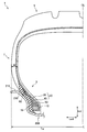
- FIG. 1 is a cross-sectional view of the tire 1 according to the present embodiment along the tire radial direction trd and the tread width direction twd.
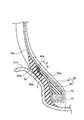
- FIG. 2 is an enlarged view of the bead portion 3 in FIG.
- FIG. 3 is an explanatory diagram illustrating a state when the tire 1 rides on the curbstone 500.
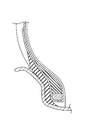
- FIG. 4 is a cross-sectional view of the tire according to Comparative Example 1 along the tire radial direction trd and the tread width direction twd.
- FIG. 5 is a cross-sectional view of the tire according to Comparative Example 2 along the tire radial direction trd and the tread width direction twd.
- FIG. 1 is a cross-sectional view of the tire 1 according to the present embodiment along the tire radial direction trd and the tread width direction twd.
- FIG. 2 is an enlarged view of the bead portion 3 in FIG.
- the tire 1 is assembled to a rim 200 that is a regular rim.
- the tire 1 has a normal internal pressure and is loaded with a normal load.
- the rim 200 is provided with a rim flange 210.
- the rim flange 210 supports the bead portion 3 in the tread width direction twd.
- the rim flange 210 includes a rim flange apex 215 at the outermost position in the tire radial direction trd.
- the “regular rim” refers to a standard rim in the applicable size defined in the Year Book 2008 version of JATMA (Japan Automobile Tire Association). Outside Japan, this refers to the standard rim at the applicable size described in the standards described below.
- Regular internal pressure is the air pressure specified by the tire measurement method of Year Book 2008 version of JATMA (Japan Automobile Tire Association) (page 0-3, item 5). Outside Japan, the “regular internal pressure” is the air pressure corresponding to the air pressure at the time of measuring the tire dimensions described in the standards described later.
- Regular load is a load corresponding to the maximum load capacity when a single wheel of the Year Book 2008 version of JATMA (Japan Automobile Tire Association) is applied. Outside Japan, the “regular load” is the maximum load (maximum load capacity) of a single wheel at the applicable size described in the standard described later.
- the tire 1 includes a bead portion 3, a tread portion 5, and a sidewall portion 7.
- the bead unit 3 has a bead core 10.
- the bead portion 3 contacts the rim 200.
- the tread portion 5 has a tread surface in contact with the road surface.
- the sidewall portion 7 forms the side surface of the tire 1.
- the sidewall portion 7 connects the bead portion 3 and the tread portion 5.
- the maximum width in the tread width direction twd is the tire maximum width TW.
- the tire maximum width TW is located in the sidewall portion 7. At the tire maximum width TW position, the thickness of the sidewall portion 7 is preferably 2.5 mm or less.
- the tire 1 includes a pair of bead cores 10, a carcass layer 20, a bead filler 50, a soft rubber member 60, and a rubber chafer 70.
- the bead core 10 is provided in the bead part 3.
- the bead core 10 is configured by a bead wire (not shown).
- the outer end of the bead core 10 in the tire radial direction trd is in contact with the bead filler 50.
- the carcass layer 20 forms a skeleton of the tire 1.
- the position of the carcass layer 20 extends from the tread portion 5 through the sidewall portion 7 to the bead portion 3.
- the carcass layer 20 has a toroidal shape straddling between the pair of bead cores 10.
- the carcass layer 20 wraps the bead core 10 and the bead filler 50 in this embodiment.
- the carcass layer 20 is in contact with the bead core 10 and the bead filler 50.
- the carcass layer 20 includes a carcass body portion 30 and a carcass folded portion 40.
- the carcass body portion 30 straddles between a pair of bead cores 10. Accordingly, the position of the carcass main body portion 30 extends from the tread portion 5 through the sidewall portion 7 to the bead portion 3.
- the carcass folding portion 40 is folded outside the tread width direction twd by the pair of bead cores 10.
- the carcass folded portion 40 includes a carcass outer end 45a that is an outer end in the tire radial direction trd.
- the carcass outer end 45 a is in contact with the carcass main body portion 30.
- the bead filler 50 increases the rigidity of the bead part 3.
- the bead filler 50 extends from the bead core 10 in the tire radial direction trd.
- the bead filler 50 is provided between the carcass main body portion 30 and the carcass folded portion 40.
- the bead filler 50 is provided outside the bead core 10 in the tire radial direction trd.
- the bead filler 50 includes a bead filler outer end 55a that is an outer end in the tire radial direction trd. As the bead filler 50 moves toward the bead filler outer end 55a, the thickness of the bead filler 50 decreases.
- the soft rubber member 60 is disposed between the carcass outer end 45 a and the rubber chafer 70. Therefore, the soft rubber member 60 overlaps the carcass outer end 45a in the tread width direction twd. The soft rubber member 60 is in contact with the carcass outer end 45 a and the rubber chafer 70.
- the soft rubber member 60 includes a soft rubber outer end 65a that is an outer end portion in the tire radial direction trd and a soft rubber inner end 65b that is an inner end portion in the tire radial direction trd.
- the hardness of the soft rubber member 60 is lower than the hardness of the bead filler 50 and the hardness of the rubber chafer 70. Hardness can be compared using 100% modulus. “100% modulus” is the tensile stress when the rubber is stretched 100%. The 100% modulus of the soft rubber member 60 is preferably 1/3 or less of the 100% modulus of the rubber chafer 70.
- the rubber chafer 70 increases the rigidity of the bead portion 3.
- the rubber chafer 70 reduces wear caused by rubbing between the tire and the rim flange during traveling.
- the rubber chafer 70 is in contact with the rim flange 210.
- the rubber chafer 70 is provided outside the carcass layer 20 and the soft rubber member 60 in the tread width direction twd.
- the rubber chafer 70 is exposed on the outer surface of the tire 1. That is, the rubber chafer 70 is located on the outermost side of the bead portion 3 in the tread width direction twd.
- a rim line is formed on the rubber chafer 70.
- the rubber chafer 70 includes a rubber chafer outer end 75a that is an outer end in the tire radial direction trd.
- the rubber chafer outer end 75 a is in contact with the carcass main body portion 30.
- the bead filler outer end 55a and the carcass outer end 45a are located inside the rim flange apex 215.
- the rubber chafer outer end 75a is positioned outside the rim flange apex 215.
- the carcass outer end 45a is positioned inside the soft rubber outer end 65a and positioned outside the soft rubber inner end 65b.
- the soft rubber outer end 65a is located inside the rim flange apex 215 in the tire radial direction trd.
- the soft rubber inner end 65b is preferably positioned on the outer side in the tire radial direction trd than the bead filler outer end 55a.
- the soft rubber outer end 65a is located inside the rim flange apex 215 in the tire radial direction trd and located outside the bead filler outer end 55a.
- the soft rubber member 60 is preferably present between the bead filler outer end 55 a and the rim flange apex 215.
- the soft rubber member 60 intersects a line connecting the bead filler outer end 55a and the rim flange apex 215.
- the soft rubber member 60 is present between the bead filler outer end 55a and the rim flange apex 215, thereby suppressing stress concentration by the soft rubber member 60 even when the bead filler outer end 55a is distorted. can do.
- the soft rubber member 60 may be disposed along the bead filler 50. Thereby, the distortion of the bead filler outer end 55a can be further suppressed, and the concentration of stress can be suppressed by the soft rubber member 60.
- FIG. 3 is an explanatory diagram illustrating a state when the tire 1 rides on the curbstone 500.
- the sidewall portion 7 is curved by the level difference. Thereafter, due to the elasticity of the sidewall portion 7, the sidewall portion 7 attempts to return to its original shape. In that case, distortion tends to concentrate on the region R from the contact portion between the bead portion 3 and the rim flange 210 to the outer portion in the tire radial direction trd.
- the rubber chafer outer end 75a is located outside the rim flange apex 215 in the tire radial direction trd. Therefore, distortion generated in the region R can be suppressed. As a result, occurrence of pinch cuts can be suppressed.
- the soft rubber member 60 is disposed between the carcass outer end 45a and the rubber chafer 70, and the hardness of the soft rubber member 60 is lower than the hardness of the bead filler 50 and the rubber chafer 70.
- the soft rubber member 60 becomes a buffer material, and it is possible to relieve the stress generated by the strain from being concentrated on the carcass layer 20. As a result, occurrence of pinch cuts can be suppressed.
- the bead filler outer end 55a and the carcass outer end 45a are located on the inner side of the rim flange apex 215 in the tire radial direction trd. Therefore, the quantity of the member used for the tire 1 can be reduced. For this reason, the weight of the tire 1 can be reduced and resource saving can be achieved.
- the bead filler outer end 55a and the carcass outer end 45a are located on the inner side of the rim flange apex 215, so that the ride comfort is also improved.
- the 100% modulus of the soft rubber member 60 is preferably 1/3 or less of the 100% modulus of the rubber chafer 70. Thereby, the concentration of stress acting on the carcass outer end 45a can be further relaxed.
- the soft rubber outer end 65a is located inside the rim flange apex 215 in the tire radial direction trd.
- the soft rubber inner end 65b is preferably positioned on the outer side in the tire radial direction trd than the bead filler outer end 55a.
- the thickness of the sidewall portion 7 is preferably 2.5 mm or less at the position of the tire maximum width TW.
- the weight of the members constituting the sidewall portion 7 can be reduced, and further resource saving can be achieved.
- the position (mm) of the carcass outer end shown in Table 1 indicates the position of the carcass outer end in the tire radial direction with the rim flange apex as a reference. If the value is positive, the outer end of the carcass is positioned outside the apex of the rim flange in the tire radial direction. If the value is negative, the outer end of the carcass is positioned on the inner side in the tire radial direction than the apex of the rim flange. The same applies to “the position (mm) of the outer end of the bead filler”.
- the rubber chafer outer end is located at the same position in each tire with the rim flange apex as a reference.
- the tire shown in FIG. 1 and FIG. 2 was used as a tire according to the example.
- a soft rubber member is arranged.
- the 100% modulus of the rubber chafer is 6 MPa, and the 100% modulus of the soft rubber member is 2 MPa.
- the tire shown in FIG. 4 was used.
- the difference from the embodiment is that, as shown in Table 1, the carcass outer end and the bead filler outer end are located outside the rim flange apex in the tire radial direction.
- the soft rubber member is not disposed.
- each tire was used to measure tire mass, anti-pinch cut performance, anti-separation performance, and riding comfort performance. With respect to each performance, the performance of other tires was indexed with reference to Comparative Example 1. The greater the number, the greater the performance. That is, the larger the tire mass value, the greater the mass. The larger the value of anti-pinch cut performance, the better the anti-pinch cut performance. The other performance is the same.
- the tire according to the present invention may be a pneumatic tire or a tire filled with rubber.
- a gas-filled tire other than air containing a rare gas such as argon may be used.
Landscapes
- Engineering & Computer Science (AREA)
- Mechanical Engineering (AREA)
- Tires In General (AREA)
Description
本実施形態に係るタイヤ1の概略構成について、図1及び図2を参照しながら説明する。図1は、本実施形態に係るタイヤ1のタイヤ径方向trd及びトレッド幅方向twdに沿った断面図である。図2は、図1におけるビード部3の拡大図である。
本実施形態に係る作用効果について、図3を参照しながら説明する。図3は、タイヤ1が縁石500に乗り上げたとき状態を表す説明図である。
本発明に係るタイヤの効果を確かめるために、以下のタイヤを用いて、タイヤ重量、耐ピンチカット性能、耐セパレーション性能を評価した。なお、本発明は、以下の実施例に限定されない。

本発明の実施形態を通じて本発明の内容を開示したが、この開示の一部をなす論述及び図面は、本発明を限定するものであると理解すべきではない。本発明はここでは記載していない様々な実施形態を含む。
Claims (5)
- 1対のビードコアと、前記1対のビードコア間に跨るトロイダル形状を有するカーカス層と、前記ビードコアからタイヤ径方向に延びるビードフィラと、リムフランジに接するゴムチェーファと、を備え、
前記カーカス層は、前記1対のビードコア間に跨るカーカス本体部分と、前記1対のビードコアでトレッド幅方向の外側に折り返されるカーカス折返し部分とを含むタイヤであって、
前記カーカス折返し部分は、前記タイヤ径方向における外側の端部であるカーカス外側端を含み、
ビードフィラは、前記タイヤ径方向における外側の端部であるビードフィラ外側端を含み、
前記ゴムチェーファは、前記タイヤ径方向における外側の端部であるゴムチェーファ外側端を含み、
前記リムフランジは、前記タイヤ径方向において、最も外側の位置にあるリムフランジ頂点を含み、
前記タイヤ径方向において、前記ビードフィラ外側端及び前記カーカス外側端は、前記リムフランジ頂点よりも、内側に位置し、
前記タイヤ径方向において、前記ゴムチェーファ外側端は、前記リムフランジ頂点よりも、外側に位置し、
前記カーカス外側端と前記ゴムチェーファとの間には、軟質ゴム部材が配置され、
前記軟質ゴム部材の硬度は、前記ビードフィラの硬度及び前記ゴムチェーファの硬度よりも低いタイヤ。 - 前記軟質ゴム部材は、前記タイヤ径方向における前記ビードフィラの外側の端部と前記リムフランジ頂点との間に存在していることを特徴とする請求項1に記載のタイヤ。
- 前記軟質ゴム部材の100%モジュラスは、前記ゴムチェーファの100%モジュラスの1/3以下である請求項1又は2に記載のタイヤ。
- 前記タイヤ径方向における前記軟質ゴム部材の外側の端部は、前記リムフランジ頂点よりも、前記タイヤ径方向において内側に位置し、
前記タイヤ径方向における前記軟質ゴム部材の内側の端部は、前記タイヤ径方向における前記ビードフィラの外側の端部よりも、前記タイヤ径方向において外側に位置する請求項1乃至3に記載のタイヤ。 - 前記タイヤの側面を形成するサイドウォール部を備え、
前記トレッド幅方向におけるタイヤ最大幅位置において、前記サイドウォール部の厚みは、2.5mm以下である請求項1から4の何れか1項に記載のタイヤ。
Priority Applications (4)
| Application Number | Priority Date | Filing Date | Title |
|---|---|---|---|
| JP2014504973A JP6068439B2 (ja) | 2012-03-14 | 2013-03-13 | タイヤ |
| EP13761466.5A EP2826643B1 (en) | 2012-03-14 | 2013-03-13 | Tire |
| US14/378,401 US20150298509A1 (en) | 2012-03-14 | 2013-03-13 | Tire |
| CN201380009289.7A CN104114382B (zh) | 2012-03-14 | 2013-03-13 | 轮胎 |
Applications Claiming Priority (2)
| Application Number | Priority Date | Filing Date | Title |
|---|---|---|---|
| JP2012056964 | 2012-03-14 | ||
| JP2012-056964 | 2012-03-14 |
Publications (1)
| Publication Number | Publication Date |
|---|---|
| WO2013137340A1 true WO2013137340A1 (ja) | 2013-09-19 |
Family
ID=49161245
Family Applications (1)
| Application Number | Title | Priority Date | Filing Date |
|---|---|---|---|
| PCT/JP2013/057065 Ceased WO2013137340A1 (ja) | 2012-03-14 | 2013-03-13 | タイヤ |
Country Status (5)
| Country | Link |
|---|---|
| US (1) | US20150298509A1 (ja) |
| EP (1) | EP2826643B1 (ja) |
| JP (1) | JP6068439B2 (ja) |
| CN (1) | CN104114382B (ja) |
| WO (1) | WO2013137340A1 (ja) |
Cited By (1)
| Publication number | Priority date | Publication date | Assignee | Title |
|---|---|---|---|---|
| JP2022112984A (ja) * | 2021-01-22 | 2022-08-03 | 株式会社ブリヂストン | 空気入りタイヤ |
Families Citing this family (6)
| Publication number | Priority date | Publication date | Assignee | Title |
|---|---|---|---|---|
| JP6659442B2 (ja) | 2016-04-27 | 2020-03-04 | 株式会社トクヤマ | 結晶性l−カルノシン亜鉛錯体の保存容器 |
| JP6848356B2 (ja) * | 2016-11-04 | 2021-03-24 | 住友ゴム工業株式会社 | 空気入りタイヤ |
| JP6787197B2 (ja) * | 2017-03-10 | 2020-11-18 | 横浜ゴム株式会社 | 空気入りタイヤの製造方法 |
| DE102017210403A1 (de) * | 2017-06-21 | 2018-12-27 | Continental Reifen Deutschland Gmbh | Elastomerprodukt aufweisend eine Markierung und Verfahren zur Herstellung |
| JP7512633B2 (ja) * | 2020-03-24 | 2024-07-09 | 住友ゴム工業株式会社 | タイヤ |
| JP7711451B2 (ja) * | 2021-06-28 | 2025-07-23 | 住友ゴム工業株式会社 | 空気入りタイヤ及びその製造方法 |
Citations (8)
| Publication number | Priority date | Publication date | Assignee | Title |
|---|---|---|---|---|
| JPS61143207A (ja) * | 1984-12-13 | 1986-06-30 | Sumitomo Rubber Ind Ltd | 重荷重用ラジアルタイヤのビ−ド部補強構造 |
| JPS61222801A (ja) * | 1985-03-29 | 1986-10-03 | Bridgestone Corp | 乗用車用ラジアルタイヤ |
| JP2001071719A (ja) * | 1999-09-06 | 2001-03-21 | Yokohama Rubber Co Ltd:The | 重荷重用空気入りラジアルタイヤ |
| JP2001138708A (ja) * | 1999-11-15 | 2001-05-22 | Toyo Tire & Rubber Co Ltd | 空気入りタイヤ |
| JP2003191723A (ja) * | 2001-12-26 | 2003-07-09 | Bridgestone Corp | 空気入りタイヤ |
| JP2007045361A (ja) * | 2005-08-11 | 2007-02-22 | Sumitomo Rubber Ind Ltd | 空気入りタイヤ |
| JP2008155728A (ja) * | 2006-12-22 | 2008-07-10 | Sumitomo Rubber Ind Ltd | 空気入りタイヤ |
| JP2008285010A (ja) | 2007-05-17 | 2008-11-27 | Sumitomo Rubber Ind Ltd | クリンチ用ゴム組成物および空気入りタイヤ |
Family Cites Families (6)
| Publication number | Priority date | Publication date | Assignee | Title |
|---|---|---|---|---|
| JPS5770707A (en) * | 1980-10-16 | 1982-05-01 | Bridgestone Corp | Pneumatic radial tire |
| JPS61119412A (ja) * | 1984-11-16 | 1986-06-06 | Bridgestone Corp | 耐久性の改良された空気入りタイヤ |
| JPH0872506A (ja) * | 1994-09-06 | 1996-03-19 | Toyo Tire & Rubber Co Ltd | 乗用車用空気入りタイヤ |
| JPH11170823A (ja) * | 1997-12-16 | 1999-06-29 | Bridgestone Corp | 重荷重用空気入りラジアルタイヤ |
| JP3837249B2 (ja) * | 1998-12-25 | 2006-10-25 | 横浜ゴム株式会社 | 乗用車用空気入りラジアルタイヤ |
| EP2465710B1 (en) * | 2009-09-16 | 2014-06-25 | Bridgestone Corporation | Air-filled radial tire |
-
2013
- 2013-03-13 CN CN201380009289.7A patent/CN104114382B/zh not_active Expired - Fee Related
- 2013-03-13 JP JP2014504973A patent/JP6068439B2/ja not_active Expired - Fee Related
- 2013-03-13 EP EP13761466.5A patent/EP2826643B1/en not_active Not-in-force
- 2013-03-13 US US14/378,401 patent/US20150298509A1/en not_active Abandoned
- 2013-03-13 WO PCT/JP2013/057065 patent/WO2013137340A1/ja not_active Ceased
Patent Citations (8)
| Publication number | Priority date | Publication date | Assignee | Title |
|---|---|---|---|---|
| JPS61143207A (ja) * | 1984-12-13 | 1986-06-30 | Sumitomo Rubber Ind Ltd | 重荷重用ラジアルタイヤのビ−ド部補強構造 |
| JPS61222801A (ja) * | 1985-03-29 | 1986-10-03 | Bridgestone Corp | 乗用車用ラジアルタイヤ |
| JP2001071719A (ja) * | 1999-09-06 | 2001-03-21 | Yokohama Rubber Co Ltd:The | 重荷重用空気入りラジアルタイヤ |
| JP2001138708A (ja) * | 1999-11-15 | 2001-05-22 | Toyo Tire & Rubber Co Ltd | 空気入りタイヤ |
| JP2003191723A (ja) * | 2001-12-26 | 2003-07-09 | Bridgestone Corp | 空気入りタイヤ |
| JP2007045361A (ja) * | 2005-08-11 | 2007-02-22 | Sumitomo Rubber Ind Ltd | 空気入りタイヤ |
| JP2008155728A (ja) * | 2006-12-22 | 2008-07-10 | Sumitomo Rubber Ind Ltd | 空気入りタイヤ |
| JP2008285010A (ja) | 2007-05-17 | 2008-11-27 | Sumitomo Rubber Ind Ltd | クリンチ用ゴム組成物および空気入りタイヤ |
Cited By (1)
| Publication number | Priority date | Publication date | Assignee | Title |
|---|---|---|---|---|
| JP2022112984A (ja) * | 2021-01-22 | 2022-08-03 | 株式会社ブリヂストン | 空気入りタイヤ |
Also Published As
| Publication number | Publication date |
|---|---|
| EP2826643A4 (en) | 2015-07-08 |
| CN104114382B (zh) | 2016-05-11 |
| US20150298509A1 (en) | 2015-10-22 |
| JPWO2013137340A1 (ja) | 2015-08-03 |
| JP6068439B2 (ja) | 2017-01-25 |
| CN104114382A (zh) | 2014-10-22 |
| EP2826643B1 (en) | 2018-08-08 |
| EP2826643A1 (en) | 2015-01-21 |
Similar Documents
| Publication | Publication Date | Title |
|---|---|---|
| JP6068439B2 (ja) | タイヤ | |
| JP4830028B2 (ja) | 重荷重用ラジアルタイヤ | |
| CN102825984A (zh) | 充气子午线轮胎 | |
| CN103502022B (zh) | 充气轮胎 | |
| JP2009286225A (ja) | 重荷重用空気入りタイヤ | |
| JP5277928B2 (ja) | 空気入りタイヤ | |
| WO2013094300A1 (ja) | 重荷重用空気入りタイヤ | |
| JP2018070110A (ja) | 空気入りタイヤ | |
| JP4919950B2 (ja) | 自動二輪車用空気入りラジアルタイヤ | |
| JP2014108683A (ja) | 空気入りタイヤ | |
| JP2012218528A (ja) | 重荷重用タイヤ | |
| JP2011051573A (ja) | 空気入りラジアルタイヤ | |
| WO2014199756A1 (ja) | ランフラットタイヤ | |
| WO2014073422A1 (ja) | タイヤ | |
| JP2012020665A (ja) | 空気入りラジアルタイヤ | |
| JP2005199762A (ja) | 重荷重用空気入りラジアルタイヤ | |
| WO2016002538A1 (ja) | タイヤ | |
| JP2010167903A (ja) | タイヤ | |
| JP2006218936A (ja) | 重荷重用空気入りラジアルタイヤ | |
| JP2010163009A (ja) | タイヤ | |
| JP5258108B2 (ja) | 空気入りラジアルタイヤ | |
| JP2015071355A (ja) | 空気入りタイヤ | |
| JP2010052612A (ja) | 空気入りラジアルタイヤ | |
| JP5215958B2 (ja) | 空気入りタイヤ | |
| JP2014231259A (ja) | 空気入りタイヤ |
Legal Events
| Date | Code | Title | Description |
|---|---|---|---|
| WWE | Wipo information: entry into national phase |
Ref document number: 201380009289.7 Country of ref document: CN |
|
| 121 | Ep: the epo has been informed by wipo that ep was designated in this application |
Ref document number: 13761466 Country of ref document: EP Kind code of ref document: A1 |
|
| ENP | Entry into the national phase |
Ref document number: 2014504973 Country of ref document: JP Kind code of ref document: A |
|
| WWE | Wipo information: entry into national phase |
Ref document number: 14378401 Country of ref document: US |
|
| NENP | Non-entry into the national phase |
Ref country code: DE |
|
| WWE | Wipo information: entry into national phase |
Ref document number: 2013761466 Country of ref document: EP |