WO2013137358A1 - Masque pour l'étalonnage et procédé d'étalonnage - Google Patents
Masque pour l'étalonnage et procédé d'étalonnage Download PDFInfo
- Publication number
- WO2013137358A1 WO2013137358A1 PCT/JP2013/057096 JP2013057096W WO2013137358A1 WO 2013137358 A1 WO2013137358 A1 WO 2013137358A1 JP 2013057096 W JP2013057096 W JP 2013057096W WO 2013137358 A1 WO2013137358 A1 WO 2013137358A1
- Authority
- WO
- WIPO (PCT)
- Prior art keywords
- mask
- unit
- exposure
- calibration
- shielding
- Prior art date
- Legal status (The legal status is an assumption and is not a legal conclusion. Google has not performed a legal analysis and makes no representation as to the accuracy of the status listed.)
- Ceased
Links
Images



Classifications
-
- G—PHYSICS
- G03—PHOTOGRAPHY; CINEMATOGRAPHY; ANALOGOUS TECHNIQUES USING WAVES OTHER THAN OPTICAL WAVES; ELECTROGRAPHY; HOLOGRAPHY
- G03F—PHOTOMECHANICAL PRODUCTION OF TEXTURED OR PATTERNED SURFACES, e.g. FOR PRINTING, FOR PROCESSING OF SEMICONDUCTOR DEVICES; MATERIALS THEREFOR; ORIGINALS THEREFOR; APPARATUS SPECIALLY ADAPTED THEREFOR
- G03F9/00—Registration or positioning of originals, masks, frames, photographic sheets or textured or patterned surfaces, e.g. automatically
- G03F9/70—Registration or positioning of originals, masks, frames, photographic sheets or textured or patterned surfaces, e.g. automatically for microlithography
- G03F9/7088—Alignment mark detection, e.g. TTR, TTL, off-axis detection, array detector, video detection
-
- G—PHYSICS
- G03—PHOTOGRAPHY; CINEMATOGRAPHY; ANALOGOUS TECHNIQUES USING WAVES OTHER THAN OPTICAL WAVES; ELECTROGRAPHY; HOLOGRAPHY
- G03F—PHOTOMECHANICAL PRODUCTION OF TEXTURED OR PATTERNED SURFACES, e.g. FOR PRINTING, FOR PROCESSING OF SEMICONDUCTOR DEVICES; MATERIALS THEREFOR; ORIGINALS THEREFOR; APPARATUS SPECIALLY ADAPTED THEREFOR
- G03F1/00—Originals for photomechanical production of textured or patterned surfaces, e.g., masks, photo-masks, reticles; Mask blanks or pellicles therefor; Containers specially adapted therefor; Preparation thereof
- G03F1/38—Masks having auxiliary features, e.g. special coatings or marks for alignment or testing; Preparation thereof
- G03F1/42—Alignment or registration features, e.g. alignment marks on the mask substrates
-
- G—PHYSICS
- G03—PHOTOGRAPHY; CINEMATOGRAPHY; ANALOGOUS TECHNIQUES USING WAVES OTHER THAN OPTICAL WAVES; ELECTROGRAPHY; HOLOGRAPHY
- G03F—PHOTOMECHANICAL PRODUCTION OF TEXTURED OR PATTERNED SURFACES, e.g. FOR PRINTING, FOR PROCESSING OF SEMICONDUCTOR DEVICES; MATERIALS THEREFOR; ORIGINALS THEREFOR; APPARATUS SPECIALLY ADAPTED THEREFOR
- G03F9/00—Registration or positioning of originals, masks, frames, photographic sheets or textured or patterned surfaces, e.g. automatically
- G03F9/70—Registration or positioning of originals, masks, frames, photographic sheets or textured or patterned surfaces, e.g. automatically for microlithography
- G03F9/7003—Alignment type or strategy, e.g. leveling, global alignment
- G03F9/7019—Calibration
Definitions
- the present invention relates to a calibration mask and a calibration method, and more particularly to a calibration mask and a calibration method for measuring the resolution of an image sensor used for exposure position control of an exposure apparatus.
- an exposure apparatus for a substrate such as a color filter of a liquid crystal display device
- the substrate and the mask are relatively fixed with an exposure mask having an exposure pattern to be exposed on the substrate in proximity to the substrate.
- exposure position adjustment means adjusts the exposure position between the substrate and the exposure mask in a direction perpendicular to the moving direction, and irradiates the exposure mask with the exposure light to transfer the exposure pattern to the substrate. What is exposed is known.
- the exposure position adjusting means includes an image sensor (for example, a line coupled device (charge coupled device) such as a line CCD).
- the image sensor simultaneously recognizes the existing pattern as a reference, such as a black matrix previously formed on the substrate, and the reference pattern on the mask, and detects the distance between the existing pattern and the reference pattern on the mask.
- a technique related to an exposure apparatus that performs control so as to correct a shift is proposed in Patent Document 1.
- the accuracy of the correction is affected by the resolution of the line CCD camera.
- the resolution of the line CCD camera depends on the angle between the mask and the substrate and the line CCD camera as well as the magnification of the condenser lens attached to the light receiving element of the CCD camera (see FIG. 6B). An error occurs.
- FIG. 6 is a schematic diagram for explaining the positional relationship between the position of the image sensor unit 25 when the calibration mask unit 35 is viewed from above and a specific portion of the calibration mask unit 35.
- the mask unit 35 can measure the resolution accurately when the shielding lines are installed in parallel with the image sensor unit 25 as a reference. If it demonstrates with reference to FIG. 6 (A), resolution information will be computable by Formula (1).
- Resolution d / (P2-P1) Expression (1)
- the resolution error is an error that can be obtained by Expression (3).
- Resolution d / (P4-P3)
- Resolution error (d ⁇ 1) ⁇ cos ⁇ / (P4 ⁇ P3) Equation (3)
- the magnification of the condenser lens of the line CCD camera can be confirmed in advance, but the angle between the mask and the substrate and the line CCD camera is difficult to actually measure, and the work of confirming the resolution of the line CCD camera in advance. Therefore, it is necessary to perform preliminary work after setting the exposure mask and the substrate in an actual exposure apparatus.
- the substrate is large and a plurality of exposure masks are arranged, and the line CCD corresponds to each exposure mask independently, there is a problem that the operation is complicated.
- the present invention provides a calibration mask capable of easily measuring the resolution of an image sensor for adjusting the exposure position of the exposure apparatus, and calibration by measuring the resolution of the image sensor of the exposure apparatus using the same. It aims to provide a method.
- the calibration mask of the present invention is composed of a mask portion having an image acquisition window for acquiring an image, and a glass material bonded to the lower side of the mask portion using an adhesive layer in the vicinity of the image acquisition window. And a shielding line group in which shielding lines composed of shielding materials are provided on the image acquisition window and the glass surface part, respectively.
- “Calibration” refers to calibrating information relating to the resolution of the image sensor used to adjust the exposure position of the exposure apparatus.
- the calibration mask of the present invention traverses the image acquisition window with at least two or more shielding lines made of a shielding material arranged on the glass surface portion so that the shielding line group traverses the image acquisition window.
- at least two or more shielding lines made of a shielding material disposed on the lower surface of the mask portion may be provided in parallel.
- the calibration mask of the present invention may be provided with a plurality of alignment marks on the surface of the mask portion.
- the shielding lines when the number of shielding lines arranged on the glass surface portion is three or more, the shielding lines may be arranged at equal intervals. In the calibration mask of the present invention, when the number of shielding lines arranged on the lower surface of the mask is three or more, the shielding lines may be arranged at equal intervals.
- the calibration method of the present invention measures the resolution of an exposure apparatus, and has a mask portion provided with an image acquisition window for acquiring an image, and is bonded to the lower side of the mask portion and in the vicinity of the image acquisition window.
- Light is applied to a calibration mask including a glass surface portion composed of a glass material bonded using a layer, and a shielding line group in which a shielding line composed of a shielding material is provided on each of the image acquisition window and the glass surface portion.
- Light that is transmitted and transmitted except for the shielding line group is received, converted into image information from above the received light, and resolution information is measured based on the image information.
- a mask portion having an image acquisition window for acquiring an image, and an adhesive layer is provided on the lower side of the mask portion and in the vicinity of the image acquisition window.
- the glass surface portion composed of the glass material, and the image acquisition window and the glass surface portion are each provided with a shielding line group provided with a shielding line composed of a shielding material on the image acquisition window. Since each shielding line group is imaged on the plurality of light receiving elements of the image sensor by imaging with the image sensor, the resolution of the image sensor can be accurately measured from this image as will be described later.
- the figure for demonstrating the structure of the exposure apparatus 100 for demonstrating the usage method of the mask part for a calibration in embodiment of this invention The figure for demonstrating the structure of the mask part for calibration in embodiment of this invention.
- the figure which expanded the image acquisition window of the mask part 35 in embodiment of this invention The figure which showed the relationship between the mask part 35 and the glass surface part 40 in embodiment of this invention
- the figure which showed the positional relationship of the position of the image sensor part 25 which looked at the mask part 35 from upper direction in the embodiment of this invention, and the specific part of the mask part 35 The figure which showed the positional relationship of the specific part of the alignment mark 75 and the mask part 35 which looked at the mask part 35 from upper direction in embodiment of this invention.
- a calibration mask according to an embodiment of the present invention and a calibration method for measuring the resolution of an image sensor of an exposure apparatus using the calibration mask will be described with reference to FIG.
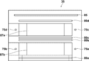
- FIG. 2 is a diagram showing the configuration of the calibration mask unit 35 according to one embodiment of the present invention.
- the mask unit 35 includes alignment marks 75a to 75d, image acquisition windows (line CCD observation windows) 80a to d, a mask ID 85, and exposure windows 87a and b, and is shown below the image acquisition window 80 in FIG. Thus, it arrange
- the mask portion 35 has the glass surface portion 40 adhered by an adhesive layer 49.
- the glass surface portion 40 is composed of a glass material bonded to the lower side of the image acquisition window 80 using an adhesive layer on the substrate side of the mask portion 35.
- the heights of the adhesive layer 49 and the glass surface 40 are set to be substantially the same as the length between the lower surface of the mask portion 37 and the upper surface of the substrate 5 of the exposure apparatus 200 shown in FIG.
- At least two or more shielding lines 45 a to 45 g made of a shielding material are evenly provided on the upper surface (mask portion 35 side) of the glass surface portion 40 so as to cross the image acquisition window 80.
- At least two shielding lines 47a to 47c made of a shielding material are provided in parallel on the lower surface of the mask portion 35 so as to cross the image acquisition window 80. It has been.
- a plurality of alignment marks 75a to 75d are provided on the surface of the mask portion 35 on the exposure portion 50 side, and the purpose is to maintain the positional relationship with the substrate.
- the shielding material used for the shielding lines 45a to 45g and the shielding lines 47a to 47c uses chromium (Cr) or the like.
- FIG. 1 shows a configuration of an exposure apparatus 100 that measures the resolution of an image sensor unit 25 used for exposure position adjustment using a calibration mask unit 35.
- the exposure apparatus 100 is a state in which the exposure target substrate is not disposed in a state where the exposure mask portion 37 (see FIG. 11) of the exposure device 200 (see FIG. 10) is replaced with the calibration mask portion 35.
- the measurement of the resolution of the image sensor unit 25 of the exposure apparatus using the calibration mask unit 35 is performed in the state shown in FIG.
- the exposure apparatus 100 includes a substrate transport unit 10 that can transport a substrate, a calibration mask unit 35, and an image sensor unit that converts light information transmitted from an image acquisition window 80 of the mask unit 35 into image information ( A line CCD camera) 25, and an image processing unit 55 that measures the resolution of the image sensor unit (line CCD camera) 25 based on image information acquired from the image sensor unit 25.
- the exposure apparatus 100 acquires image information of the substrate transport unit 10 that transports the substrate, the exposure unit 50 that can irradiate exposure light from above the mask unit 35, and the mask unit 35.
- An image detection light source unit 20 that emits light from below the mask unit 35, and an image sensor unit (line CCD camera) that is above the mask unit 35 and receives light from the image detection light source unit 20 to acquire image information.
- an image processing unit 55 that measures the resolution of the image sensor unit (line CCD camera) 25 based on the image information acquired by the image sensor unit 25, and a mask unit position adjustment unit 70. .
- the image processing unit 55 determines the reference mark of the exposure mask unit 37 from the image sensor unit (line CCD camera) 25 in the exposure process.
- the amount of positional deviation between the exposure mask portion 37 and the substrate 5 is calculated from the image of the reference mark on the substrate, and a signal is sent to the mask portion position adjustment unit 70 based on the result, and the mask portion position adjustment unit 70
- the position of the exposure mask portion 37 is adjusted.
- the exposure apparatus 100 may include an exposure control unit 60 that can control the exposure position of the exposure unit 50 based on the measured resolution information.
- the calibration mask unit 35 since the calibration mask unit 35 is used for measuring the resolution, it is not necessary to irradiate from the exposure unit 50. Therefore, the calibration mask unit 35 does not have to include an exposure window, but the calibration mask unit 35 described below will be described as an example having an exposure window.
- the substrate transport unit 10 transports a substrate.
- the substrate transport unit 10 is configured to place the substrate 5 and transport the substrate 5 in a predetermined transport direction.
- a plurality of unit stages having suction holes are juxtaposed in the transport direction of the substrate 5, and the substrate 5 is floated on the plurality of unit stages by a predetermined amount due to the balance between gas ejection and suction by the transport rollers.
- the both ends of the substrate 5 are supported and conveyed.
- the exposure apparatus 200 shown in FIG. 10 replaces the calibration mask unit 35 with the exposure mask unit 37 after the resolution of the positioning image sensor unit 25 is measured using the calibration mask unit 35, and is attached to the substrate 5. Exposure.
- the exposure unit 50 irradiates ultraviolet rays, and the exposure wavelength range is 280 to 400 nm, for example.
- the exposure unit 50 irradiates ultraviolet rays, and specifically is a laser oscillator, a xenon flash lamp, or the like.
- a photo integrator (not shown) may be mounted on the exposure unit 50, and the luminance distribution in the cross section of the exposure light irradiated from the exposure unit 50 is made uniform.
- the photo integrator may be a fly-eye lens, a rod lens, a light pipe, or the like.
- a condenser lens mounted on the exposure unit 50 converts the exposure light into parallel light and irradiates the exposure mask unit 37 of the exposure apparatus 200 described later.
- the exposure unit 50 performs exposure in accordance with a control command from the exposure control unit 60.
- the alignment marks 75a to 75d of the calibration mask unit 35 are used to confirm whether or not the set position of the calibration mask unit 35 is parallel to the image sensor unit 25. Is.
- the image sensor unit 25 captures the alignment marks 75a to 75d of the calibration mask unit 35, and the image processing unit 55 processes the image.
- the set position of the calibration mask unit 35 and the position of the image sensor unit 25 This is for confirming whether or not the relationship is parallel.
- the mask unit position adjustment unit 70 adjusts the position of the calibration mask unit 35 in accordance with the positional relationship information between the image sensor unit 25 and the set position of the calibration mask unit 35 from the image processing unit 55.
- the positional relationship between the set position of the calibration mask unit 35 and the image sensor unit 25 is made parallel.
- the image acquisition windows (image sensor observation windows) 80a to 80d transmit light emitted from the image detection light source unit 20.
- the mask ID 85 describes the identification number of the calibration mask unit 35.
- the exposure windows 87a and 87b transmit the exposure light emitted from the exposure unit 50.
- FIG. 3 is an enlarged view of the image acquisition window 80 of the mask unit 35.
- FIG. 4 is a diagram showing the relationship between the calibration mask portion 35 and the glass surface portion 40.
- FIG. 5 is a diagram showing details of the configuration of the mask portion 35 and the glass surface portion 40.
- the image processing unit 55 measures resolution information of the image sensor unit 25 based on the image information acquired from the image sensor unit 25 that has received the transmitted light except for the shielding wire groups 45a to 45g and 47a to 47c. It is.
- the exposure control unit 60 controls the exposure start and stop positions of the exposure unit 50 based on the resolution information measured by the image processing unit 55.
- This calibration method is a method for measuring the resolution of the exposure apparatus 100, and includes a mask unit 35 having an image acquisition window 80 for acquiring an image, and a lower side of the mask unit 35, and the image acquisition window 80.
- a glass surface portion 40 composed of a glass material adhered using an adhesive layer in the vicinity thereof, and a shielding line group in which shielding lines composed of a shielding material are provided on the image acquisition window 80 and the glass surface portion 40, respectively.
- the image detection light source unit 20 is turned on, and the calibration mask unit 35 is irradiated with illumination light from below.
- the image sensor unit 25 images the alignment marks 75a and 75b, and the image Is processed by the image processing unit 55, and an angle formed by an imaginary line connecting the centers of the alignment marks 75a and 75b and the image sensor unit 25 is calculated.
- the calibration mask unit 35 is rotated (rotated about an axis perpendicular to the surface of the calibration mask unit 35) by the mask position adjustment unit 70 so that the calculated angle is minimized, and the calibration mask unit 35 and The image sensor unit 25 is set in parallel.
- image information is acquired by receiving light transmitted by the image sensor unit 25 excluding the shielding lines 45a to 45g and the shielding lines 47a to 47c having different heights from the shielding lines 45a to 45g. To do.
- the image sensor unit 25 acquires image information so that the focus area differs for each of the area where the shielding lines 45a to 45g are imaged and the area where the shielding lines 47a to 47c are imaged.
- the image sensor unit 25 is a multifocal camera, for example, a bifocal camera having two focal points as shown in FIG. Specifically, each of the shielding lines 45a to 45g on the glass surface portion 40 and the shielding lines 47a to 47c facing the mask portion 35 can be focused, and both can be photographed clearly.
- a light adjusting plate 25a is interposed in half the field of view of the image sensor unit 25, and simultaneously focuses on the shielding lines 45a to 45g on the glass surface part 40 and the shielding line 47 of the mask part 35 having different focal depths. Has come to fit. Then, the image processing unit 55 measures the resolution using the image information and the distance between the shielding lines on the image sensor unit 25.
- the distance between the heights of the shielding lines 45a to 45g and the shielding lines 47a to 47c is set equal to the exposure gap of the exposure apparatus.
- the exposure apparatus 200 sets a gap (for example, about 100 ⁇ m) between the mask portion 37 and the substrate 5 as an exposure gap.
- the image sensor unit 25 can measure resolution information for each focus area by using the shielding lines 45a to 45g and the shielding lines 47a to 47c having different heights.
- FIG. 8 is a conceptual diagram for explaining the positional relationship between specific portions of the image sensor unit 25 and the mask unit 35 when the calibration mask unit 35 is viewed from above. As shown in FIG. 8, the image sensor unit 25 has an area for capturing the shielding lines 45a to 45g and an area for capturing the shielding lines 45a to 45g and the shielding lines 47a to 47c having different heights. The image information is acquired so that the focus areas are different.
- the image processing unit 55 measures the resolution using the image information and the distance of the shielding line interval on the image sensor unit 25.
- the image sensor unit 25 sets a plurality of regions so as to have different focal lengths, and the image processing unit 55 can measure resolution information for each set region.
- the image processing unit 55 calculates a plate focus area (Plate Focus Area) and a mask focus area (Mask Focus Area), which are different focus areas, using Expressions (4) and (5). To do.
- Resolution (Plate Focus Area) d1 / (p2-p1)
- Resolution (Mask Focus Area) d2 / (p4-p3) Formula (5)
- the image processing unit 55 can calculate the resolution for each different focus area.
- FIG. 9 is a diagram showing an example of image information acquired by the image sensor unit 25.
- the focus area is divided into an exposure gap (Gap) of 100 to 180 ⁇ m, a plate focus area, and an exposure gap (Gap) of 200 to 300 ⁇ m.
- exposure gaps (Gap) of 100 to 180 ⁇ m represent lines L1 to L3 that are shielded by the shielding lines.
- the plate focus area is represented by L4 to L9.
- L5 and L8 are lines shielded by a shielding line different from L4, 6 and 9.
- exposure gaps (Gap) 200 to 300 ⁇ m represent lines L10 to L12 shielded by the shielding lines. In this way, the resolution measurement unit can calculate the resolution for each different focus area.
- An exposure apparatus 200 shown in FIG. 10 is obtained by replacing the calibration mask unit 35 with an exposure mask unit 37, and controls the exposure position of the exposure unit 50 based on the resolution information described above.
- the exposure control unit 60 sets the distance between the shielding lines having different heights as the exposure gap distance.
- the exposure apparatus 100 provided with the calibration mask unit 35 has the above-described configuration.
- the alignment marks 75a to 75d of the calibration mask unit 35 are read by an image sensor (not shown) different from the image sensor unit 25, and the setting position of the calibration mask unit 35 and the image sensor unit 25 are It may be confirmed whether or not the positional relationship is parallel.
- the exposure apparatus 200 controls exposure by using the resolution information of the image sensor unit 25 calculated by the exposure apparatus 100 and actually exposes the substrate 5.
- the exposure apparatus 200 includes a substrate transport unit 10 that transports the substrate 5, an exposure unit 50 that irradiates exposure light from above the substrate 5, and image information of the substrate 5.
- An image detection light source unit 20 that emits light from below, an image sensor unit 25 that is above the substrate 5 and receives light from the image detection light source unit 20 to acquire image information, a substrate transport unit 10, and exposure
- An exposure window 22 that is disposed between the units 50 and transmits part of the exposure light emitted from the exposure unit 50 and an image acquisition window 23 that transmits part of the light emitted from the image detection light source unit 20 are provided.
- the exposure mask unit 37 provided, the exposure control unit 60 for controlling the exposure position of the exposure unit 50 based on the resolution information calculated by the exposure apparatus 100, and the mask unit position adjustment unit 70 are provided.
- the substrate 5 is a glass substrate.
- the substrate 5 may be a TFT substrate or a color filter substrate on which a wiring pattern is formed.
- FIG. 11 is a diagram schematically showing the configuration of the exposure mask portion 37 and the substrate 5.
- the exposure mask portion 37 has a light shielding portion and an exposure window formed in a predetermined pattern on the surface of a transparent substrate made of quartz glass or the like.
- An arrow “a” in the figure indicates the transport direction of the substrate 5.
- the exposure mask portion 37 has a configuration in which, for example, vertically long slit-shaped exposure windows 22 are formed in parallel at a predetermined pitch along a direction perpendicular to the substrate transport direction a.
- the area subjected to the light shielding process indicates the light shielding portion 21, and the area not subjected to the light shielding process indicates the exposure window 22.
- An image acquisition window 23 having a horizontally long slit shape is formed on the conveyance start side of the exposure mask portion 37 with respect to the substrate 5.
- a shielding line 46 is formed in the image acquisition window 23.
- the light shielding unit 21 is shielded by, for example, chromium.
- the shielding wire 46 is also made of a shielding material such as chrome.
- the image sensor unit 25 photographs an existing pattern formed in advance on the substrate 5, for example, a gate bus line, a source bus line, or a black matrix, through the image acquisition window 23 of the exposure mask unit 37. At this time, the image sensor unit 25 performs photographing for detecting an image from the start end to the other end end of the existing pattern 4 that extends in the drawing in the vertical direction in the drawing formed in parallel with the transport direction a of the substrate 5. The image sensor unit 25 detects an image of the existing pattern 4 that moves so as to flow in a strip shape under the image acquisition window 23 by photographing with the image sensor unit 25.
- the image sensor unit 25 A shift amount is calculated by the image processing unit 55 from the image data, and the mask portion position adjusting unit 70 moves for alignment of the exposure mask portion 37 according to the shift amount. In this way, alignment adjustment is performed by movement control of the exposure mask portion 37 following the existing pattern 4. As a result, the exposure unit 50 performs accurate exposure on the position along the existing pattern 4.
- Substrate transport unit 20 Image detection light source unit 21 Light blocking unit 22 Exposure window 23 Image acquisition window 25 Image sensor unit 25a Light adjustment plate 35 Mask unit 37 Mask unit 40 Glass surface unit 45a to g Shielding line 46 Shielding line 47a to c Shielding Line 50 Exposure unit 55 Image processing unit 60 Exposure control unit 70 Mask unit position adjustment unit 75 Alignment mark 80 Image acquisition window 87 Exposure window 100 Exposure apparatus 200 Exposure apparatus
Landscapes
- Physics & Mathematics (AREA)
- General Physics & Mathematics (AREA)
- Engineering & Computer Science (AREA)
- Multimedia (AREA)
- Exposure And Positioning Against Photoresist Photosensitive Materials (AREA)
Priority Applications (2)
| Application Number | Priority Date | Filing Date | Title |
|---|---|---|---|
| CN201380014388.4A CN104169802B (zh) | 2012-03-15 | 2013-03-13 | 校正用掩模及校正方法 |
| KR1020147028186A KR20140141644A (ko) | 2012-03-15 | 2013-03-13 | 교정용 마스크 및 교정 방법 |
Applications Claiming Priority (2)
| Application Number | Priority Date | Filing Date | Title |
|---|---|---|---|
| JP2012-059481 | 2012-03-15 | ||
| JP2012059481A JP5928032B2 (ja) | 2012-03-15 | 2012-03-15 | キャリブレーション用マスクおよびキャリブレーション方法 |
Publications (1)
| Publication Number | Publication Date |
|---|---|
| WO2013137358A1 true WO2013137358A1 (fr) | 2013-09-19 |
Family
ID=49161263
Family Applications (1)
| Application Number | Title | Priority Date | Filing Date |
|---|---|---|---|
| PCT/JP2013/057096 Ceased WO2013137358A1 (fr) | 2012-03-15 | 2013-03-13 | Masque pour l'étalonnage et procédé d'étalonnage |
Country Status (4)
| Country | Link |
|---|---|
| JP (1) | JP5928032B2 (fr) |
| KR (1) | KR20140141644A (fr) |
| CN (1) | CN104169802B (fr) |
| WO (1) | WO2013137358A1 (fr) |
Families Citing this family (1)
| Publication number | Priority date | Publication date | Assignee | Title |
|---|---|---|---|---|
| JP3366176B2 (ja) | 1996-02-22 | 2003-01-14 | ダイハツ工業株式会社 | バッテリの充電方法 |
Citations (2)
| Publication number | Priority date | Publication date | Assignee | Title |
|---|---|---|---|---|
| WO2007113933A1 (fr) * | 2006-04-05 | 2007-10-11 | Sharp Kabushiki Kaisha | Procede et dispositif d'exposition |
| JP2007299805A (ja) * | 2006-04-27 | 2007-11-15 | Nsk Ltd | ギャップ検出値の校正方法 |
Family Cites Families (1)
| Publication number | Priority date | Publication date | Assignee | Title |
|---|---|---|---|---|
| JPS6222435A (ja) * | 1985-07-23 | 1987-01-30 | Nippon Seiko Kk | 投影露光装置に使用する原点校正用マスク |
-
2012
- 2012-03-15 JP JP2012059481A patent/JP5928032B2/ja active Active
-
2013
- 2013-03-13 WO PCT/JP2013/057096 patent/WO2013137358A1/fr not_active Ceased
- 2013-03-13 KR KR1020147028186A patent/KR20140141644A/ko not_active Withdrawn
- 2013-03-13 CN CN201380014388.4A patent/CN104169802B/zh not_active Expired - Fee Related
Patent Citations (2)
| Publication number | Priority date | Publication date | Assignee | Title |
|---|---|---|---|---|
| WO2007113933A1 (fr) * | 2006-04-05 | 2007-10-11 | Sharp Kabushiki Kaisha | Procede et dispositif d'exposition |
| JP2007299805A (ja) * | 2006-04-27 | 2007-11-15 | Nsk Ltd | ギャップ検出値の校正方法 |
Also Published As
| Publication number | Publication date |
|---|---|
| JP5928032B2 (ja) | 2016-06-01 |
| JP2013195467A (ja) | 2013-09-30 |
| KR20140141644A (ko) | 2014-12-10 |
| CN104169802A (zh) | 2014-11-26 |
| CN104169802B (zh) | 2016-02-03 |
Similar Documents
| Publication | Publication Date | Title |
|---|---|---|
| TWI446122B (zh) | 曝光裝置 | |
| TWI475337B (zh) | 對位方法、對位裝置及曝光裝置 | |
| TWI578096B (zh) | 校正用光罩及校正方法 | |
| TWI570519B (zh) | 曝光微影裝置以及曝光微影方法 | |
| JP4971835B2 (ja) | 露光方法及び露光装置 | |
| TWI578110B (zh) | 曝光裝置及曝光結束材料之製造方法 | |
| CN105005182A (zh) | 多个传感器间相互位置关系校准方法 | |
| KR20080067915A (ko) | 마스크 리스 노광 장치 및 그의 정렬 방법 | |
| TWI472885B (zh) | 校準方法、校準裝置及曝光裝置 | |
| JP5928032B2 (ja) | キャリブレーション用マスクおよびキャリブレーション方法 | |
| JP5804511B2 (ja) | 露光装置 | |
| CN105209977B (zh) | 曝光装置 | |
| CN101238416B (zh) | 曝光装置及被曝光体 | |
| JP4764237B2 (ja) | 露光装置 | |
| JP2005197483A (ja) | 撮像手段の回転誤差計測方法、及びこの回転誤差計測方法を用いた調整方法又は計測方法、及びこの回転誤差計測方法で計測された回転誤差を使用する位置計測装置、及びこの位置計測装置を備えた露光装置 | |
| JP4557799B2 (ja) | デジタルカメラの調整方法及び、その調整装置 | |
| KR20040002511A (ko) | 투영 노광장치 | |
| JP2013195468A (ja) | 基板 | |
| CN111512240A (zh) | 光敏记录介质上至少一幅存储图像的曝光方法和曝光设备 | |
| CN209388110U (zh) | 一种可在线检测底片涨缩的全自动曝光平台 | |
| JP2006234647A (ja) | 位置計測方法、位置計測装置、露光方法及び露光装置 | |
| JP2005243710A5 (fr) | ||
| CN121002451A (zh) | 投影曝光装置 | |
| JP2013210433A (ja) | ワークの姿勢検出方法、ワークの姿勢調整方法、ワークの姿勢検出装置、ワークの姿勢調整装置、および投影露光装置 |
Legal Events
| Date | Code | Title | Description |
|---|---|---|---|
| 121 | Ep: the epo has been informed by wipo that ep was designated in this application |
Ref document number: 13761408 Country of ref document: EP Kind code of ref document: A1 |
|
| NENP | Non-entry into the national phase |
Ref country code: DE |
|
| ENP | Entry into the national phase |
Ref document number: 20147028186 Country of ref document: KR Kind code of ref document: A |
|
| 122 | Ep: pct application non-entry in european phase |
Ref document number: 13761408 Country of ref document: EP Kind code of ref document: A1 |