WO2013137409A1 - 2,3,3,3-テトラフルオロプロペンおよび1,1-ジフルオロエチレンの製造方法 - Google Patents
2,3,3,3-テトラフルオロプロペンおよび1,1-ジフルオロエチレンの製造方法 Download PDFInfo
- Publication number
- WO2013137409A1 WO2013137409A1 PCT/JP2013/057258 JP2013057258W WO2013137409A1 WO 2013137409 A1 WO2013137409 A1 WO 2013137409A1 JP 2013057258 W JP2013057258 W JP 2013057258W WO 2013137409 A1 WO2013137409 A1 WO 2013137409A1
- Authority
- WO
- WIPO (PCT)
- Prior art keywords
- reactor
- tetrafluoropropene
- tfe
- hfo
- difluoroethylene
- Prior art date
- Legal status (The legal status is an assumption and is not a legal conclusion. Google has not performed a legal analysis and makes no representation as to the accuracy of the status listed.)
- Ceased
Links
Images
Classifications
-
- C—CHEMISTRY; METALLURGY
- C07—ORGANIC CHEMISTRY
- C07C—ACYCLIC OR CARBOCYCLIC COMPOUNDS
- C07C17/00—Preparation of halogenated hydrocarbons
- C07C17/26—Preparation of halogenated hydrocarbons by reactions involving an increase in the number of carbon atoms in the skeleton
- C07C17/263—Preparation of halogenated hydrocarbons by reactions involving an increase in the number of carbon atoms in the skeleton by condensation reactions
- C07C17/269—Preparation of halogenated hydrocarbons by reactions involving an increase in the number of carbon atoms in the skeleton by condensation reactions of only halogenated hydrocarbons
-
- C—CHEMISTRY; METALLURGY
- C07—ORGANIC CHEMISTRY
- C07C—ACYCLIC OR CARBOCYCLIC COMPOUNDS
- C07C17/00—Preparation of halogenated hydrocarbons
- C07C17/25—Preparation of halogenated hydrocarbons by splitting-off hydrogen halides from halogenated hydrocarbons
Definitions
- the present invention relates to a method for producing 2,3,3,3-tetrafluoropropene and 1,1-difluoroethylene, and in particular, from a raw material containing chlorodifluoromethane and chloromethane and tetrafluoroethylene in one reaction.
- the present invention relates to a process for producing 2,3,3,3-tetrafluoropropene and 1,1-difluoroethylene.
- HFO-1234yf 2,3,3,3-tetrafluoropropene
- HFC-134a 1,1,1,2-tetrafluoroethane
- HFO-1234yf 1,1-dichloro-2,2,3,3,3-pentafluoropropane (HCFC-225ca) is removed with an alkaline aqueous solution in the presence of a phase transfer catalyst.
- HCFC-225ca 1,1-dichloro-2,2,3,3,3-pentafluoropropane
- CFO-1214ya 1,1-dichloro-2,3,3,3-tetrafluoropropene obtained by hydrogen fluoride is used as a synthetic raw material and reduced by hydrogen.
- Patent Document 1 by combining different types of hydrochlorocarbons (for example, chloromethane and chlorodifluoromethane), heating to 845 ⁇ 5 ° C. in the presence of water vapor, dehydrochlorination / condensation, It has been suggested that fluorine-containing olefins such as HFO-1234yf have been produced.
- Patent Document 2 a mixture of chloromethane and tetrafluoroethylene (TFE) or chlorodifluoromethane is heated and decomposed to a temperature of 700 to 950 ° C. by a normal heating means such as an electric heater in a reactor. Thus, a method for obtaining HFO-1234yf has been proposed.
- TFE tetrafluoroethylene
- the present invention has been made from the above viewpoint, and is an economy in which HFO-1234yf useful as a new refrigerant is produced in a sufficiently high yield by a single reaction involving thermal decomposition using raw materials that are easily procured. It is an object to provide a particularly advantageous method. It is another object of the present invention to provide a method for obtaining high-purity HFO-1234yf by suppressing the formation of CTFE, which is a by-product that is difficult to be separated from HFO-1234yf by distillation.
- the present invention relates to 2,3,3,3-tetrafluoropropene (HFO-1234yf) and 1,1-difluoroethylene (HFO-1234yf) from chlorodifluoromethane (R22), chloromethane (R40) and tetrafluoroethylene (TFE).
- VdF comprising: (A) mixing R22, R40 and TFE in advance or separately supplying them to the reactor; (b) supplying a heat medium to the reactor; and (c) the reaction.
- a method for producing HFO-1234yf and VdF comprising: bringing the heat medium into contact with R22, R40, and TFE in a container to generate HFO-1234yf and VdF. To do.
- R22, R40, and TFE which are easily procured, are reacted as they are without taking out the intermediate product from the reaction system, and HFO-1234yf useful as a new refrigerant is sufficiently high in yield.
- HFO-1234yf useful as a new refrigerant is sufficiently high in yield.
- HFO-1234yf since the production of by-products such as CTFE, which is difficult to be separated from HFO-1234yf, is suppressed, high-purity HFO-1234yf can be obtained. Furthermore, together with HFO-1234yf, it is possible to produce 1,1-difluoroethylene (VdF), which is useful as a raw material for polyvinylidene fluoride used as a material for water treatment filters and various manufacturing machine parts. Is big. Furthermore, TFE produced as a by-product can be recycled, which has a great economic effect.
- VdF 1,1-difluoroethylene
- the present invention provides a method for producing HFO-1234yf and VdF by a synthesis reaction involving thermal decomposition using chlorodifluoromethane (R22), chloromethane (R40) and tetrafluoroethylene (TFE) as raw materials. And this manufacturing method (A) supplying the R22, the R40, and the TFE to the reactor after being mixed in advance or separately; (B) supplying a heat medium to the reactor; (C) bringing the heating medium into contact with the R22, R40 and the TFE in the reactor to generate the HFO-1234yf and the VdF.
- R22 chlorodifluoromethane
- R40 chloromethane
- TFE tetrafluoroethylene
- the production method of the present invention may be a continuous production method or a batch production method.
- supply of the raw materials R22, R40 and TFE to the reactor, supply of the heat medium to the reactor, and removal of the reaction mixture containing HFO-1234yf and VdF from the reactor are performed. Both are performed continuously.
- either the supply of the raw material in the step (a) or the supply of the heat medium in the step (b) may be earlier or at the same time. That is, when one of the raw material and the heat medium is supplied, even if the other is not supplied into the reactor, the component supplied later is retained during the retention of the previously supplied raw material or the heat medium.
- the raw material and the heat medium that are supplied may be in contact with each other for a predetermined time in the reactor.
- the production method of the present invention is preferably a continuous method in terms of production efficiency.
- step (d) The step of taking out the reaction mixture containing HFO-1234yf and VdF from the reactor is hereinafter referred to as step (d). Therefore, in the continuous manufacturing method, the steps (a), (b), and (d) are all performed simultaneously.
- a mixture containing difluorocarbene (F 2 C :) and TFE and R40 is formed by pyrolysis and dehydrochlorination reaction in the reactor.
- F 2 C : difluorocarbene
- TFE and R40 is converted to tetrafluoropropene (particularly HFO-1234yf) or VdF via one or more intermediates.
- these thermal decomposition reactions to the formation reaction of HFO-1234yf and VdF are referred to as synthesis reactions involving thermal decomposition.
- the ratio of HFO-1234yf in the obtained reaction mixture is high, especially as a relative ratio with CTFE, which is difficult to distill from HFO-1234yf. can do.
- the ratio (molar ratio) of the content ratio of HFO-1234yf and CTFE in the reaction mixture is 9 as the molar amount of HFO-1234yf / CTFE (hereinafter referred to as “HFO-1234yf / CTFE”). 0 or more.
- HFO-1234yf / CTFE is preferably 10.0 or more, more preferably 15.0 or more. If the value of HFO-1234yf / CTFE is 9.0 or more, it is economically superior as a method for producing HFO-1234yf. Further, the present invention has an advantage that the raw material can be handled safely.
- HFO-1234yf of the present invention uses R22, R40 and TFE as raw materials.
- the raw material is a compound that can be decomposed by contact with a heat medium in the reactor to generate difluorocarbene (F 2 C :), such as hexafluoropropene (hereinafter referred to as HFP), CTFE.
- F 2 C difluorocarbene
- HFP hexafluoropropene
- CTFE CTFE
- RC318 Trifluoroethylene
- RC318 octafluorocyclobutane
- hexafluoropropene oxide and the like.
- fluorine compounds other than R22 and TFE that can be thermally decomposed in a reactor to generate F 2 C: are referred to as “HFP and the like”.
- the molar ratio of the supply amount of TFE, which is one of the raw material components, to the supply amount of R22 is preferably in the range of 0.01 to 100.
- a range of 0.1 to 10 is more preferable, and a range of 0.1 to 3 is particularly preferable.
- the supply amount of each component of the raw material and the heat medium indicates the supply amount per unit time.
- the molar ratio of the R40 supply amount to the total of the R22 supply amount and the TFE supply amount (hereinafter referred to as R40 / (R22 + TFE)) should be in the range of 0.01 to 100.
- a range of 0.1 to 10 is more preferable, and a range of 0.33 to 3 is particularly preferable.
- the temperature of R22 supplied to the reactor and the temperature of HFP or the like supplied to the reactor are preferably set to 0 to 600 ° C. from the viewpoint that the reactivity is somewhat high but is not easily carbonized. From the viewpoint of enhancing the reactivity, it is preferable to heat to normal temperature (25 ° C.) or higher and 600 ° C. or lower, and more preferably 100 to 500 ° C. before introducing R22, HFP, and the like into the reactor. preferable.
- the temperature of R40 supplied to the reactor is preferably 0 to 1200 ° C. from the viewpoint of reactivity. From the standpoint of further increasing the reactivity, it is preferable to heat to normal temperature (25 ° C.) or higher and 1200 ° C.
- the temperature of TFE supplied to the reactor is preferably 0 to 1200 ° C. from the viewpoint of reactivity. From the viewpoint of increasing the reactivity, it is preferable to heat to normal temperature (25 ° C.) or higher and 1200 ° C. or lower, more preferably 100 to 800 ° C. before introducing TFE into the reactor.
- the raw material components such as R22, R40, TFE, and HFP used as necessary may be supplied to the reactor separately or may be supplied after mixing the components.
- the raw materials are divided into groups, for example, a fluorine-containing compound capable of generating F 2 C: and other components, and each component is mixed in each group. May be supplied separately to the reactor, or may be supplied after mixing all the components.
- R22, TFE and HFP used as necessary are mixed, adjusted to the preferred temperature and supplied to the reactor, and separately, R40 is adjusted to the preferred temperature. Then, it is preferable to supply to the reactor.
- the temperature at the time of feeding to the reactor is preferably less than 600 ° C, and particularly preferably less than 500 ° C.
- the heat medium in the present invention is supplied to the reactor so as to be in contact with the raw material for a certain time in the reactor.
- the heat medium is a medium that does not undergo thermal decomposition at the temperature in the reactor, and specifically, a medium that does not undergo thermal decomposition at a temperature of 100 to 1200 ° C. is preferable.
- Examples of the heat medium include one or more gases selected from water vapor, nitrogen, and carbon dioxide, and it is preferable to use a gas that contains 50% by volume or more of water vapor and the balance is nitrogen and / or carbon dioxide.
- the content ratio of water vapor in the heat medium is preferably 50% by volume or more, and a gas substantially consisting of only water vapor (100% by volume) Use is particularly preferred.
- the supply amount of the heat medium is preferably 20 to 98% by volume, more preferably 50 to 95% by volume of the total supply amount of the heat medium and the raw material.
- the temperature of the heat medium supplied to the reactor is preferably 100 to 1200 ° C. from the viewpoint of thermal decomposition and reactivity of raw material components. From the viewpoint of further increasing the reactivity of the raw material components, the temperature of the heat medium introduced into the reactor is more preferably 600 to 900 ° C, and particularly preferably 700 to 900 ° C.
- the contact time of the heat medium supplied in this manner with the raw material in the reactor is preferably 0.01 to 10 seconds, and more preferably 0.2 to 3.0 seconds. By setting the contact time to 0.01 to 10 seconds, the production reaction of HFO-1234yf and the like can sufficiently proceed and the production of by-products can be suppressed.
- the contact time between the heat medium and the raw material corresponds to the residence time of the raw material in the reactor, and can be controlled by adjusting the supply amount (flow rate) of the raw material to the reactor.
- the shape of the reactor is not particularly limited as long as it can withstand the temperature and pressure in the reactor described later, and examples thereof include a cylindrical vertical reactor.
- Examples of the material of the reactor include glass, iron, nickel, or an alloy mainly composed of iron and nickel.
- the temperature in the reactor is preferably equal to or higher than the temperatures of the raw materials R22, R40 and TFE supplied to the reactor, and preferably 400 to 1200 ° C.
- a range of 600 to 900 ° C. is more preferable, and a range of 710 to 900 ° C. is particularly preferable.
- the temperature in the reactor can be controlled by adjusting the temperature and pressure of the heat medium supplied to the reactor. Further, the inside of the reactor can be supplementarily heated with an electric heater or the like so that the temperature in the reactor falls within a particularly preferable temperature range (710 to 900 ° C.).
- the pressure in the reactor is preferably 0 to 2 MPa in gauge pressure, and more preferably in the range of 0 to 0.5 MPa.
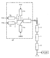
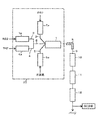
- the reaction apparatus 20 has a reactor 1 provided with heating means such as an electric heater.
- the reactor 1 includes a supply line 2 for R40 as a first raw material component, a supply line 3 for R22 as a second raw material component, a supply line 4 for TFE as a third raw material component, and a supply line for steam. 5 are connected as shown below.
- installation of the heating means in the reactor 1 is not essential.
- the R40 supply line 2, the R22 supply line 3 and the TFE supply line 4 are provided with preheaters (preheaters) 2a, 3a and 4a each equipped with an electric heater or the like. After being preheated to a predetermined temperature, it is supplied to the reactor 1.
- the steam supply line 5 is provided with a superheated steam generator 5a, and the temperature and pressure of the steam supplied are adjusted.
- installation of the preheater (preheater) 2a, 3a, 4a is not essential.
- raw material supply lines 2, 3, and 4 may be separately connected to the reactor 1, but as shown in FIG. 2, R22 and TFE in which the raw material supply line 3 and the raw material supply line 4 are connected.
- a raw material supply line 6 may be connected to the reactor 1. Further, for example, as shown in FIG. 1, after passing through each preheater 3a, 4a, the R22 supply line 3 and the TFE supply line 4 are connected, and the connected R22 and TFE raw material supply line 6 are connected.
- the supply line 2 of R40 after passing through the preheater 2a may be further connected. That is, after preheated R22 and TFE are mixed, preheated R40 is further mixed with the raw material mixture of R22 and TFE, and all the raw material components are mixed in this way.
- the steam may be supplied to the reactor 1 after being mixed with some or all of the raw materials, but it is preferable to supply the water vapor to the reactor separately from the raw materials. That is, as shown in FIG. 1 and FIG. 2, it is preferable that the steam is supplied from the steam supply line 5 to the reactor 1 separately from the raw material mixture.
- An outlet line 9 provided with a cooling means 8 such as a heat exchanger is connected to the outlet of the reactor 1.
- a water vapor and acidic liquid recovery tank 10 In the outlet line 9, a water vapor and acidic liquid recovery tank 10, an alkali cleaning device 11 and a dehydration tower 12 are further installed in this order. Then, after dehydration by the dehydration tower 12, each component of the obtained gas is analyzed and quantified by an analyzer such as gas chromatography (GC).
- GC gas chromatography
- outlet gas A gas obtained by removing a reaction mixture containing HFO-1234yf and TFE from the reactor 1 and removing acidic substances such as hydrogen chloride, water vapor, water, etc.
- HFO-1234yf and VdF can be obtained as components of the outlet gas.
- Compounds other than HFO-1234yf and VdF contained in the outlet gas include methane, ethylene, TFE, HFP, CTFE, trifluoroethylene, RC318, 3,3,3-trifluoropropene (CF 3 CH ⁇ CH 2 : HFO-1243zf) and the like.
- methane and ethylene having a methylene group ( ⁇ CH 2 ) or a methyl group (—CH 3 ) are compounds derived from the raw material component R40, and include TFE, HFP, CTFE, Trifluoroethylene, RC318, and HFO-1243zf are all compounds derived from R22 and / or TFE among the raw material components.
- HFO-1234yf and VdF are compounds derived from R22 and / or TFE, as well as compounds derived from R40.
- HFO-1234yf and VdF contained in the outlet gas can be removed to a desired extent by known means such as distillation.
- the separated TFE can be recycled as a part of the raw material.
- HFP, CTFE, trifluoroethylene, and RC318 are also compounds that can generate a difluorocarbene radical (CF 2 :), and can be recycled as part of the raw material.
- CTFE contained in the exit gas as a by-product is difficult to distill from HFO-1234yf due to its close boiling point, but the ratio of CTFE byproduct to the amount of HFO-1234yf produced is low, so the purity by distillation purification is low. High HFO-1234yf can be obtained.
- HFO-1234yf useful as a new refrigerant having a small global warming potential (GWP) of 4 in a single reaction is sufficiently high in yield.
- GWP global warming potential
- the production method of the present invention can not only reduce the cost required for raw materials and production equipment, but also significantly reduce the energy required for production, compared to the conventional method for producing HFO-1234yf. can do.
- VdF which is a raw material for polyvinylidene fluoride, which is industrially used as a water treatment filter, for example, can be manufactured. And can be manufactured simultaneously.
- the same thermal decomposition / dehydrochlorination reaction occurs due to contact with the heat medium to generate HFO-1234yf and VdF.
- the contact time between the raw material and the heat medium in the reactor can be shortened as compared with the case where the binary raw material is used.
- CTFE has a boiling point of ⁇ 28 ° C. and is very close to the boiling point of HFO-1234yf ( ⁇ 29 ° C.).
- the ratio of the amount of CTFE produced to the amount of HFO-1234yf produced can be greatly reduced by using ternary raw materials of R22, R40 and TFE. High purity HFO-1234yf can be obtained.
- Example 1 Using the reaction apparatus shown in FIG. 1, crude HFO-1234yf and crude VdF were obtained from a raw material gas composed of R22, R40 and TFE as follows.
- R40 was continuously introduced into a stainless steel tube in an electric furnace set at a furnace temperature of 300 ° C., and R40 was heated to 300 ° C. (preheating).
- R22 was continuously introduce
- TFE was continuously introduced into the stainless steel tube in the electric furnace set to a furnace temperature of 300 ° C., and the TFE was preheated to 300 ° C.
- the flow rate of the source gas (amount supplied per unit time) was controlled so that the residence time of the source gas in the reactor was 0.5 seconds, and the gas of the reaction mixture was taken out from the outlet of the reactor.
- the actually measured value of the reactor internal temperature was 800 ° C.
- the actually measured value of the reactor internal pressure was 0.042 MPa.
- the gas of the reaction mixture taken out from the outlet of the reactor includes unreacted source gas in addition to the gas generated or by-produced by the reaction.
- the gas of the reaction mixture taken out from the outlet of the reactor is cooled to 100 ° C. or lower, and after the vapor and acidic liquid are recovered and alkali washed sequentially, dehydration treatment is performed, and the obtained outlet gas is subjected to gas chromatography. Analysis was performed to calculate the molar composition of the gas component contained in the outlet gas. These results are shown in Table 1 together with the reaction conditions.
- the preheating temperature of R40, R22, and TFE is a preset temperature in each electric furnace for preheating
- water vapor temperature is a preset temperature in the electric furnace for steam heating.
- the water vapor pressure is a set pressure.
- Selectivity of each component derived from R40 Of the reacted R40, the percentage converted to each component other than R40 is the percentage of each. The selectivity of each component is obtained by “yield of each component derived from R40” / “conversion rate of R40 (reaction rate)”. In addition, the yield of each component derived from R40 refers to the proportion (mol%) of each component other than R40 among the components derived from R40 in the outlet gas.
- R22 and TFE conversion (reaction rate) Of the components derived from R22 and / or TFE, which are compounds containing fluorine atoms in the outlet gas (components having fluorine atoms), the proportion of R22 and / or TFE (R22 and / or TFE recovery) is X%. (100-X)% is referred to as the conversion rate (reaction rate) of R22 and / or TFE. It means the ratio (mol%) of reacted R22 and / or TFE. (Selectivity of each component derived from R22 and / or TFE) Among the reacted R22 and / or TFE, the percentage obtained as each component other than R22 each means.
- the selectivity of each component is determined by “yield of each component derived from R22 and / or TFE” / “conversion rate (reaction rate) of R22 and / or TFE”.
- the yield of each component derived from R22 and / or TFE refers to the proportion (mol%) of each component other than R22 in the components derived from R22 and / or TFE in the outlet gas.
- HFO-1234yf / CTFE ratio This is the ratio of the abundance ratio of HFO-1234yf to the abundance ratio of CTFE in the outlet gas. It is determined by “selectivity of H22-1234yf derived from R22 and / or TFE” / “selectivity of CTFE derived from R22 and / or TFE”. It represents the ratio (molar ratio) of HFO-1234yf to CTFE in the outlet gas.
- Example 2 The molar ratio (TFE / (TFE + R22)) of the TFE supply amount and the total supply amount of TFE and R22 is 0.1 (10%) in Example 2, and 0.3 (30%) in Example 3. In Example 4, it was 0.7 (70%). Further, the molar ratio of R40 / (TFE + R22) was 0.55 in Example 2, 0.65 in Example 3, and 0 in Example 4 so that the equivalent ratio of R40 / (TFE + R22) was 0.5. .85. Otherwise, the reaction was conducted under the same conditions as in Example 1.
- the gas of the reaction mixture taken out from the outlet of the reactor is cooled to 100 ° C. or lower, and after performing steam and acidic liquid recovery and alkali washing in order, dehydration treatment is performed, and the resulting outlet gas is analyzed by gas chromatography Then, the molar composition of the gas component contained in the outlet gas is calculated, and based on the obtained molar composition of the outlet gas, the conversion rate (reaction rate) of R40, the selectivity of each component derived from R40, R22 and The TFE conversion (reaction rate), the selectivity of each component derived from R22 and / or TFE, and the ratio of HFO-1234yf to CTFE (HFO-1234yf / CTFE) were determined. The results are shown in the lower column of Table 1.
- R40 was continuously introduced into a stainless steel tube in an electric furnace set at a furnace temperature of 300 ° C., and R40 was heated to 300 ° C. (preheating). Moreover, R22 was continuously introduce
- the volume ratio of the supply amount of water vapor to the supply amount of the entire gas supplied to the reactor (the flow volume ratio of water vapor) is 90% by volume as in Example 1. Then, the flow rate of the raw material gas was controlled so that the residence time of the raw material gas in the reactor was 0.5 seconds, and the gas of the reaction mixture was taken out from the outlet of the reactor.
- the actually measured value of the reactor internal temperature was 800 ° C., and the actually measured value of the reactor internal pressure was 0.42 MPa.
- the gas of the reaction mixture taken out from the outlet of the reactor is cooled to 100 ° C. or lower, and after performing steam and acidic liquid recovery and alkali washing in order, dehydration treatment is performed, and the resulting outlet gas is analyzed by gas chromatography Then, the molar composition of the gas component contained in the outlet gas is calculated, and based on the obtained molar composition of the outlet gas, the conversion rate (reaction rate) of R40, the selectivity of each component derived from R40, R22 and The TFE conversion (reaction rate), the selectivity of each component derived from R22 and / or TFE, and the ratio of HFO-1234yf to CTFE (HFO-1234yf / CTFE) were determined. The results are shown in the lower column of Table 1.
- Example 5 R40, R22, and TFE were not preheated, and each raw material component at room temperature (10 ° C.) was supplied to the reactor as it was. Otherwise, the reaction was conducted under the same conditions as in Example 1.
- the gas of the reaction mixture taken out from the outlet of the reactor is cooled to 100 ° C. or lower, and after performing steam and acidic liquid recovery and alkali washing in order, dehydration treatment is performed, and the resulting outlet gas is analyzed by gas chromatography Then, the molar composition of the gas component contained in the outlet gas is calculated, and based on the obtained molar composition of the outlet gas, the conversion rate (reaction rate) of R40, the selectivity of each component derived from R40, R22 and The TFE conversion (reaction rate), the selectivity of each component derived from R22 and / or TFE, and the ratio of HFO-1234yf to CTFE (HFO-1234yf / CTFE) were determined. The results are shown in the lower column of Table 1.
- TFE was not used as a raw material gas, and a raw material consisting only of R22 and R40 was used. And R40 and R22 were not preheated, and each raw material component at room temperature (10 ° C.) was supplied to the reactor as it was. Otherwise, the reaction was conducted under the same conditions as in Example 1.
- the gas of the reaction mixture taken out from the outlet of the reactor is cooled to 100 ° C. or lower, and after performing steam and acidic liquid recovery and alkali washing in order, dehydration treatment is performed, and the resulting outlet gas is analyzed by gas chromatography Then, the molar composition of the gas component contained in the outlet gas is calculated, and the conversion ratio (reaction rate) of R40, the selectivity of each component derived from R40, R22 and / or TFE is obtained from the molar composition of the outlet gas obtained. Conversion rate (reaction rate), selectivity of each component derived from R22 and / or TFE, and a ratio of HFO-1234yf to CTFE (HFO-1234yf / CTFE), respectively. The results are shown in the lower column of Table 1.
- the total selectivity of HFO-1234yf and VdF based on R40 is 95.7% (22.6% + 73.1%), and the molar ratio of HFO-1234yf to CTFE (HFO-1234yf / CTFE) is as large as 19.14.
- HFO-1234yf and VdF based on R40 is 96.4% (22.0% + 74.4%), which is slightly larger than Example 1, but the HFO relative to CTFE.
- the production molar ratio of ⁇ 1234yf (HFO-1234yf / CTFE) was 8.74, which was significantly reduced compared to Example 1.
- Example 1 compared to Comparative Example 1, the production of CTFE relative to the production of HFO-1234yf is suppressed, and HFO-1234yf with higher purity can be obtained. Also, in Examples 2 to 5, compared with Comparative Examples 1 and 2, the production of CTFE with respect to the production of HFO-1234yf is suppressed, and HFO-1234yf / CTFE is increased, so that HFO-1234yf with higher purity is produced. It can be seen that
- Table 1 shows the following. That is, when TFE is used as a part of the raw material, and the molar ratio of TFE in TFE + R22 (TFE / (TFE + R22)) is 10% or more, the HFO ⁇ in the outlet gas regardless of the presence or absence of preheating of the raw material components.
- the yield of 1234yf is increased, especially the selectivity for HFO-1234yf derived from R22 and / or TFE. Therefore, it can be seen that the use of TFE as a part of the raw material is an effective method for selectively obtaining HFO-1234yf.
- Example 6 to 9 In Examples 6 to 8, the reaction was carried out under the same conditions as in Example 1 except that the reactor internal temperature was changed as shown in Table 2. In Example 9, the reaction was carried out under the same conditions as in Example 1 except that the reactor shown in FIG. 2 was used and the preheat temperature of R40 was changed as shown in Table 2. Next, the gas of the reaction mixture taken out from the outlet of the reactor was treated in the same manner as in Example 1, and then the obtained outlet gas was analyzed in the same manner as in Example 1. The results are shown in Table 2 together with the reaction conditions.
- HFO-1234yf useful as a new refrigerant can be produced in a sufficiently high yield in one reaction using R22, R40, and TFE, which are easily procured, as a raw material.
- R22, R40, and TFE which are easily procured
Landscapes
- Chemical & Material Sciences (AREA)
- Organic Chemistry (AREA)
- Chemical Kinetics & Catalysis (AREA)
- Organic Low-Molecular-Weight Compounds And Preparation Thereof (AREA)
Abstract
熱分解を伴う1回の反応で、新冷媒として有用なHFO-1234yfを十分に高い収率で製造する経済的に有利な方法を提供する。 R22とR40とTFEとを含む原料から、熱分解を伴う合成反応によりHFO-1234yfおよびVdFを製造する方法であって、(a)前記R22と前記R40と前記TFEとを、予め混合して、または別々に反応器に供給する工程と、(b)熱媒体を反応器に供給する工程と、(c)反応器内で前記R22、前記R40および前記TFEに前記熱媒体を接触させて、前記HFO-1234yfと前記VdFを生成させる工程とを有する製造方法を提供する。
Description
本発明は、2,3,3,3-テトラフルオロプロペンおよび1,1-ジフルオロエチレンの製造方法に係り、特に、クロロジフルオロメタンとクロロメタンおよびテトラフルオロエチレンを含む原料から、1回の反応で2,3,3,3-テトラフルオロプロペンおよび1,1-ジフルオロエチレンを製造する方法に関する。
2,3,3,3-テトラフルオロプロペン(HFO-1234yf)は、温室効果ガスである1,1,1,2-テトラフルオロエタン(HFC-134a)に代わる新しい冷媒として、近年大きな期待が寄せられている。なお、本明細書において、ハロゲン化炭化水素については、化合物名の後の括弧内にその化合物の略称を記すが、本明細書では必要に応じて化合物名に代えてその略称を用いる。
このようなHFO-1234yfの製造方法としては、例えば、1,1-ジクロロ-2,2,3,3,3-ペンタフルオロプロパン(HCFC-225ca)を相間移動触媒の存在下にアルカリ水溶液で脱フッ化水素させて得られる1,1-ジクロロ-2,3,3,3-テトラフルオロプロペン(CFO-1214ya)を合成原料とし、水素により還元して製造する方法が知られている。
しかし、このような方法では、多段階の反応を経るため設備コストが高くなる、中間生成物や最終生成物における蒸留・精製が難しい、などの問題がある。
一方、特許文献1には、異なる種類のハイドロクロロカーボン(例えば、クロロメタンとクロロジフルオロメタン)を組み合わせて、水蒸気の共存下に845±5℃に加熱し、脱塩化水素・縮合させることにより、HFO-1234yfのようなフッ素含有オレフィン類が生成したことが提示されている。
また、特許文献2には、クロロメタンと、テトラフルオロエチレン(TFE)またはクロロジフルオロメタンの混合物を、反応器内で電気ヒータのような通常の加熱手段により700~950℃の温度に加熱・分解して、HFO-1234yfを得る方法が提示されている。
また、特許文献2には、クロロメタンと、テトラフルオロエチレン(TFE)またはクロロジフルオロメタンの混合物を、反応器内で電気ヒータのような通常の加熱手段により700~950℃の温度に加熱・分解して、HFO-1234yfを得る方法が提示されている。
しかしながら、特許文献1および特許文献2に示された方法ではいずれも、1回の反応でHFO-1234yfが生成するものの、クロロトリフルオロエチレン(CTFE)のようなHFO-1234yfとの蒸留分離が難しい副生物の生成量が多くなり、高純度のHFO-1234yfを十分に高い収率で得ることができなかった。
さらに、特許文献2に示された方法では、滞留時間の増加に伴って高沸物の生成や原料のカーボン化が起こり、反応器が閉塞するおそれがあった。また、副生する酸分の影響から、特殊な耐腐食装置(例えば、プラチナでライニングされた反応管等)が必要であり、工業的な製造を考えた場合、現実的な方法とはいえなかった。
本発明は、上記観点からなされたものであり、調達の容易な原料を使用し、熱分解を伴う1回の反応で、新冷媒として有用なHFO-1234yfを十分に高い収率で製造する経済的に有利な方法を提供することを目的とする。また、HFO-1234yfとの蒸留分離が難しい副生物であるCTFEの生成を抑え、高純度のHFO-1234yfを得る方法を提供することを目的とする。
本発明は、クロロジフルオロメタン(R22)とクロロメタン(R40)とテトラフルオロエチレン(TFE)とから、2,3,3,3-テトラフルオロプロペン(HFO-1234yf)および1,1-ジフルオロエチレン(VdF)を製造する方法であって、
(a)前記R22と前記R40と前記TFEとを、予め混合して、または別々に反応器に供給する工程と、(b)熱媒体を前記反応器に供給する工程と、(c)前記反応器内で前記R22、前記R40および前記TFEに前記熱媒体を接触させて、前記HFO-1234yfと前記VdFを生成させる工程と、を有することを特徴とするHFO-1234yfおよびVdFの製造方法を提供する。
(a)前記R22と前記R40と前記TFEとを、予め混合して、または別々に反応器に供給する工程と、(b)熱媒体を前記反応器に供給する工程と、(c)前記反応器内で前記R22、前記R40および前記TFEに前記熱媒体を接触させて、前記HFO-1234yfと前記VdFを生成させる工程と、を有することを特徴とするHFO-1234yfおよびVdFの製造方法を提供する。
本発明の製造方法によれば、調達が容易なR22とR40とTFEを原料として、中間生成物を反応系から取り出すことなく、そのまま反応させ、新冷媒として有用なHFO-1234yfを十分に高い収率で製造することができる。したがって、従来公知のHFO-1234yfを製造する方法に比べて、原料および製造設備に要するコストを大幅に低減することができる。
また、CTFEのような、HFO-1234yfとの蒸留分離が難しい副生物の生成が抑えられるので、高純度のHFO-1234yfを得ることができる。さらに、HFO-1234yfとともに、水処理フィルターや各種製造機械部品等の材料として使用されるポリフッ化ビニリデンの原料として有用な1,1-ジフルオロエチレン(VdF)を製造することができ、経済的なメリットが大きい。またさらに、副生するTFEのリサイクルも可能であり、経済的な効果が大きい。
以下に、本発明の実施の形態について説明する。
本発明は、原料として、クロロジフルオロメタン(R22)とクロロメタン(R40)およびテトラフルオロエチレン(TFE)を用い、熱分解を伴う合成反応により、HFO-1234yfおよびVdFを製造する方法を提供する。そして、この製造方法は、
(a)前記R22、前記R40および前記TFEを、予め混合してまたは別々に反応器に供給する工程と、
(b)熱媒体を反応器に供給する工程と、
(c)前記反応器内で前記R22、前記R40および前記TFEに前記熱媒体を接触させて、前記HFO-1234yfと前記VdFを生成させる工程とを有する。
本発明は、原料として、クロロジフルオロメタン(R22)とクロロメタン(R40)およびテトラフルオロエチレン(TFE)を用い、熱分解を伴う合成反応により、HFO-1234yfおよびVdFを製造する方法を提供する。そして、この製造方法は、
(a)前記R22、前記R40および前記TFEを、予め混合してまたは別々に反応器に供給する工程と、
(b)熱媒体を反応器に供給する工程と、
(c)前記反応器内で前記R22、前記R40および前記TFEに前記熱媒体を接触させて、前記HFO-1234yfと前記VdFを生成させる工程とを有する。
本発明の製造方法は、連続式の製造方法であっても、バッチ式の製造方法であってもよい。連続式の製造方法において、原料であるR22、R40およびTFEの反応器への供給と、熱媒体の反応器への供給、およびHFO-1234yfとVdFを含む反応混合物の前記反応器からの取り出しは、いずれも連続的に行われる。バッチ式の製造において、(a)工程における原料の供給と(b)工程における熱媒体の供給とは、どちらが先であっても、あるいは同時であってもよい。すなわち、原料と熱媒体のいずれか一方の供給の際に、他方が反応器内に供給されていない場合でも、先に供給された原料または熱媒体の滞留中に、後から供給される成分が供給され、原料と熱媒体とが反応器内で所定の時間接触すればよい。
本発明の製造方法は、製造効率の点で連続式の方法であるのが好ましい。以下、本発明の方法を連続式の製造に適用する実施形態について説明するが、これに限定されない。
なお、前記反応器からHFO-1234yfとVdFを含む反応混合物を取り出す工程を、以下、工程(d)という。したがって、上記連続的な製造方法においては、上記工程(a)、工程(b)、工程(d)はすべて同時に行われる。
本発明の製造方法は、製造効率の点で連続式の方法であるのが好ましい。以下、本発明の方法を連続式の製造に適用する実施形態について説明するが、これに限定されない。
なお、前記反応器からHFO-1234yfとVdFを含む反応混合物を取り出す工程を、以下、工程(d)という。したがって、上記連続的な製造方法においては、上記工程(a)、工程(b)、工程(d)はすべて同時に行われる。
<HFO-1234yfの生成反応>
本発明においては、反応器内で、以下の式(1)に示す熱分解および脱塩化水素を伴う合成反応が生起し、HFO-1234yfおよびVdFが生成する。

本発明においては、反応器内で、以下の式(1)に示す熱分解および脱塩化水素を伴う合成反応が生起し、HFO-1234yfおよびVdFが生成する。
原料であるR22とR40とTFEから反応器内で熱分解および脱塩化水素反応により、ジフルオロカルベン(F2C:)およびTFEとR40とを含む混合物が生成し、これらは、直接付加反応して、あるいは1種以上の中間体を経て、テトラフルオロプロペン(特にHFO-1234yf)やVdFへと転化されると考えられる。本発明においては、これら熱分解反応からHFO-1234yfとVdFの生成反応までを、熱分解を伴う合成反応という。
原料としてR22とR40とを用い、TFEを用いない二元系の場合も、熱媒体との接触により同様な熱分解・脱塩化水素反応が生起してHFO-1234yfが生成するが、R22とR40とTFEの三元系の原料を使用する本発明においては、前記二元系の原料を使用する場合に比べて、反応器内での原料と熱媒体との接触時間を短縮できる。また、副生物の生成を抑制し、純度の高いHFO-1234yfを得ることができる。これらの効果については、後からさらに詳しく記載する。
さらに、R22とR40とTFEの三元系の原料を使用することで、得られる反応混合物におけるHFO-1234yfの割合を、特にHFO-1234yfとの蒸留分離が難しいCTFEとの相対的な割合として高くすることができる。具体的には、反応混合物におけるHFO-1234yfとCTFEの含有割合の比(モル比)を、HFO-1234yfのモル量/CTFEのモル量(以下、「HFO-1234yf/CTFE」と示す)として9.0以上とすることができる。HFO-1234yf/CTFEは、好ましくは10.0以上であり、さらに好ましくは15.0以上である。HFO-1234yf/CTFEの値が9.0以上であれば、HFO-1234yfの製造方法として経済的に優位性が高い。
さらに、本発明においては、安全に原料のハンドリングを行うことができるという利点がある。
さらに、本発明においては、安全に原料のハンドリングを行うことができるという利点がある。
<原料>
本発明のHFO-1234yfの製造は、R22とR40とTFEを原料として用いる。原料は、前記3成分以外に、反応器内で熱媒体との接触により分解してジフルオロカルベン(F2C:)を発生し得る化合物、例えば、ヘキサフルオロプロペン(以下、HFPという。)、CTFE、トリフルオロエチレン、オクタフルオロシクロブタン(以下、RC318という。)、ヘキサフルオロプロペンオキサイド等を含有することができる。
以下、R22およびTFE以外の、反応器内で熱分解してF2C:を発生しうる含フッ素化合物を「HFP等」という。
本発明のHFO-1234yfの製造は、R22とR40とTFEを原料として用いる。原料は、前記3成分以外に、反応器内で熱媒体との接触により分解してジフルオロカルベン(F2C:)を発生し得る化合物、例えば、ヘキサフルオロプロペン(以下、HFPという。)、CTFE、トリフルオロエチレン、オクタフルオロシクロブタン(以下、RC318という。)、ヘキサフルオロプロペンオキサイド等を含有することができる。
以下、R22およびTFE以外の、反応器内で熱分解してF2C:を発生しうる含フッ素化合物を「HFP等」という。
原料成分の一つであるTFEの供給量とR22の供給量とのモル比(以下、TFE/R22と示す。)は、0.01~100の範囲とするのが好ましい。0.1~10の範囲がより好ましく、0.1~3の範囲が特に好ましい。なお、原料および熱媒体を、反応器内を連続的に流通させて反応を行わせる本実施形態において、原料各成分および熱媒体の供給量は、単位時間当たりの供給量を示すものとする。モル比TFE/R22を0.1以上とすることで、熱媒体との接触時間を短縮できるうえに、副生物の生成を抑制し純度の高いHFO-1234yfを得ることができる。また、モル比TFE/R22を10以下とすることで、より高い収率でHFO-1234yfを得ることができる。モル比TFE/R22は、0.1~3の範囲が特に好ましい。
また、R40の供給量と、前記R22の供給量と前記TFEの供給量の合計とのモル比(以下、R40/(R22+TFE)と示す。)は、0.01~100の範囲とするのが好ましいが、0.1~10の範囲がより好ましく、0.33~3の範囲が特に好ましい。モル比R40/(R22+TFE)を0.01~100とすることにより、R40の転化率を上げ、HFO-1234yfを高い収率で製造することができる。
反応器に供給するR22の温度、および反応器に供給するHFP等の温度は、反応性がある程度高いがカーボン化はしにくい温度とするという観点から、0~600℃とするのが好ましい。
より反応性を高めるという観点からは、R22、およびHFP等を反応器に導入する前に、常温(25℃)以上600℃以下に加熱することが好ましく、100~500℃に加熱することがより好ましい。
また、反応器に供給するR40の温度は、反応性の観点から0~1200℃とするのが好ましい。より反応性を高めるという観点からは、R40を反応器に導入する前に、常温(25℃)以上1200℃以下に加熱することが好ましく、100~800℃に加熱することがより好ましい。
反応器に供給するTFEの温度は、反応性の観点から0~1200℃とするのが好ましい。より反応性を高めるという観点からは、TFEを反応器に導入する前に、常温(25℃)以上1200℃以下に加熱することが好ましく、100~800℃に加熱することがより好ましい。
R22とR40とTFE、さらに必要に応じて用いられるHFP等の各原料成分の反応器への供給は、別々であってもよいし、各成分を混合してから供給してもよい。各成分を混合してから供給する場合には、原料をグループに分けて、例えばF2C:を発生し得る含フッ素化合物とそれ以外とに分けて、各グループで各成分を混合し、グループごとに反応器に別々に供給してもよいし、全成分を混合してから供給してもよい。上記供給温度の違いを考慮すれば、R22とTFEと必要に応じて用いられるHFP等を混合し、上記好ましい温度に調整して反応器に供給し、これとは別にR40を上記好ましい温度に調整して反応器に供給することが好ましい。
なお、R22とR40とTFE、さらには必要に応じて用いられるHFP等の各原料成分を、予め混合してから反応器に供給する場合、反応器の手前で分解・反応が進行してしまうことを防ぐという観点から、反応器に供給する際の温度は600℃未満にすることが好ましく、特に500℃未満にすることが好ましい。
なお、R22とR40とTFE、さらには必要に応じて用いられるHFP等の各原料成分を、予め混合してから反応器に供給する場合、反応器の手前で分解・反応が進行してしまうことを防ぐという観点から、反応器に供給する際の温度は600℃未満にすることが好ましく、特に500℃未満にすることが好ましい。
<熱媒体>
本発明における熱媒体は、前記原料と反応器内で一定の時間接触するように、反応器に供給される。熱媒体は、反応器内の温度で熱分解が生じない媒体であり、具体的には100~1200℃の温度で熱分解しない媒体であるのが好ましい。熱媒体としては、水蒸気、窒素および二酸化炭素から選ばれる1種以上の気体が挙げられ、水蒸気を50体積%以上含み、残部が窒素および/または二酸化炭素である気体の使用が好ましい。前記式(1)の熱分解反応で生成するHClを塩酸にして除くために、熱媒体における水蒸気の含有割合は50体積%以上が好ましく、実質的に水蒸気のみ(100体積%)からなる気体の使用が特に好ましい。
本発明における熱媒体は、前記原料と反応器内で一定の時間接触するように、反応器に供給される。熱媒体は、反応器内の温度で熱分解が生じない媒体であり、具体的には100~1200℃の温度で熱分解しない媒体であるのが好ましい。熱媒体としては、水蒸気、窒素および二酸化炭素から選ばれる1種以上の気体が挙げられ、水蒸気を50体積%以上含み、残部が窒素および/または二酸化炭素である気体の使用が好ましい。前記式(1)の熱分解反応で生成するHClを塩酸にして除くために、熱媒体における水蒸気の含有割合は50体積%以上が好ましく、実質的に水蒸気のみ(100体積%)からなる気体の使用が特に好ましい。
熱媒体の供給量は、熱媒体および原料の供給量の合計の20~98体積%となる割合が好ましく、50~95体積%がより好ましい。熱媒体および原料の供給量の合計に対する熱媒体の供給量の割合を20体積%以上とすることで、高沸物の生成や原料のカーボン化を抑制しながら上記式(1)の熱分解反応を進行させて、HFO-1234yfおよびVdFを十分に高い収率で製造できるようになる。また、前記割合が98体積%を超えると、生産性が著しく低下するため、工業的に現実的でない。
また、反応器に供給する熱媒体の温度は、その熱分解と原料成分の反応性の観点から100~1200℃とするのが好ましい。原料成分の反応性をより高めるという観点からは、反応器に導入する熱媒体の温度を600~900℃とすることがより好ましく、700~900℃とするのが特に好ましい。
また、反応器に供給する熱媒体の温度は、その熱分解と原料成分の反応性の観点から100~1200℃とするのが好ましい。原料成分の反応性をより高めるという観点からは、反応器に導入する熱媒体の温度を600~900℃とすることがより好ましく、700~900℃とするのが特に好ましい。
このように供給される熱媒体と前記原料との反応器内での接触時間は、0.01~10秒間とするのが好ましく、0.2~3.0秒間とするのがより好ましい。接触時間を0.01~10秒間とすることで、HFO-1234yf等の生成反応を十分に進行させ、かつ副生物の生成を抑えることができる。なお、熱媒体と原料との接触時間は、原料の反応器内での滞留時間に相当し、原料の反応器への供給量(流量)を調節することで制御できる。
<反応器>
反応器としては、後述する反応器内温度および圧力に耐えるものであれば、特に形状は限定されず、例えば円筒状の縦型反応器が挙げられる。反応器の材質としては、ガラス、鉄、ニッケル、または鉄、ニッケルを主成分とする合金等が挙げられる。
反応器としては、後述する反応器内温度および圧力に耐えるものであれば、特に形状は限定されず、例えば円筒状の縦型反応器が挙げられる。反応器の材質としては、ガラス、鉄、ニッケル、または鉄、ニッケルを主成分とする合金等が挙げられる。
工程(c)における反応器内の温度は、反応器に供給される原料であるR22、R40およびTFEの温度以上の温度とし、かつ400~1200℃とすることが好ましい。600~900℃の範囲がさらに好ましく、710~900℃の範囲が特に好ましい。反応器内の温度を400~1200℃とすることで、前記式(1)で示される熱分解を伴う生成反応の反応率を高め、HFO-1234yf等を十分に高い収率で得ることができる。
反応器内の温度は、反応器に供給される前記熱媒体の温度および圧力を調整することで制御することができる。また、前記反応器内の温度が特に好ましい温度範囲(710~900℃)になるように、電気ヒータ等により反応器内を補助的に加熱することもできる。
反応器内の圧力は、ゲージ圧で0~2MPaとすることが好ましく、0~0.5MPaの範囲がさらに好ましい。
<反応装置>
本発明において、HFO-1234yf等の製造に使用される反応装置の一例を、図1および図2に示す。
反応装置20は、電気ヒータ等の加熱手段を備えた反応器1を有する。反応器1には、第1の原料成分であるR40の供給ライン2、第2の原料成分であるR22の供給ライン3、第3の原料成分であるTFEの供給ライン4、および水蒸気の供給ライン5が、以下に示すように接続されている。なお、反応器1における加熱手段の設置は必須ではない。
本発明において、HFO-1234yf等の製造に使用される反応装置の一例を、図1および図2に示す。
反応装置20は、電気ヒータ等の加熱手段を備えた反応器1を有する。反応器1には、第1の原料成分であるR40の供給ライン2、第2の原料成分であるR22の供給ライン3、第3の原料成分であるTFEの供給ライン4、および水蒸気の供給ライン5が、以下に示すように接続されている。なお、反応器1における加熱手段の設置は必須ではない。
R40の供給ライン2、R22の供給ライン3およびTFEの供給ライン4には、それぞれ電気ヒータ等を備えた予熱器(プレヒータ)2a、3a、4aが設置されており、供給される各原料成分が所定の温度に予熱されてから反応器1に供給される。また、水蒸気の供給ライン5には、過熱水蒸気発生器5aが設置されており、供給される水蒸気の温度および圧力が調整される。なお、予熱器(プレヒータ)2a、3a、4aの設置は必須ではない。
これらの原料供給ライン2、3、4は、それぞれ別々に反応器1に接続されていてもよいが、図2に示すように、原料供給ライン3と原料供給ライン4を連結させたR22およびTFE原料供給ライン6が反応器1に接続されていてもよい。また、たとえば、図1に示すように、それぞれの予熱器3a、4aを経た後にR22の供給ライン3とTFEの供給ライン4とを連結するとともに、この連結されたR22およびTFE原料供給ライン6に、予熱器2aを経た後のR40の供給ライン2をさらに連結してもよい。すなわち、まず予熱後のR22とTFEとを混合した後、このR22とTFEとの原料混合物に、予熱したR40をさらに混合し、このように全ての原料成分が混合されたものが、原料混合供給ライン7から反応器1に供給されるように構成することができる。
一方、水蒸気は、原料の一部または全部の原料と混合した後に反応器1に供給してもよいが、原料とは別個に反応器に供給することが好ましい。すなわち、図1および図2に示すように、水蒸気は水蒸気供給ライン5から原料混合物とは別個に反応器1に供給されるように構成することが好ましい。
一方、水蒸気は、原料の一部または全部の原料と混合した後に反応器1に供給してもよいが、原料とは別個に反応器に供給することが好ましい。すなわち、図1および図2に示すように、水蒸気は水蒸気供給ライン5から原料混合物とは別個に反応器1に供給されるように構成することが好ましい。
反応器1の出口には、熱交換器のような冷却手段8が設置された出口ライン9が接続されている。出口ライン9には、さらに、水蒸気および酸性液回収槽10、アルカリ洗浄装置11および脱水塔12が順に設置されている。そして、脱水塔12により脱水された後、得られたガスの各成分がガスクロマトグラフィ(GC)のような分析装置により分析・定量されるようになっている。
なお、HFO-1234yfとTFEを含有する反応混合物が反応器1から取り出され、上記のように出口ライン9以降の処理によって塩化水素などの酸性物質、水蒸気、水などが除去されて得られたガスを以下出口ガスという。
なお、HFO-1234yfとTFEを含有する反応混合物が反応器1から取り出され、上記のように出口ライン9以降の処理によって塩化水素などの酸性物質、水蒸気、水などが除去されて得られたガスを以下出口ガスという。
<出口ガス成分>
本発明の製造方法においては、HFO-1234yfおよびVdFを前記出口ガスの成分として得ることができる。出口ガスに含有されるHFO-1234yfとVdF以外の化合物としては、メタン、エチレン、TFE、HFP、CTFE、トリフルオロエチレン、RC318、3,3,3-トリフルオロプロペン(CF3CH=CH2:HFO-1243zf)等が挙げられる。これらの成分のうちで、メチレン基(=CH2)またはメチル基(-CH3)を有するメタンおよびエチレンは、原料成分のR40に由来する化合物であり、フッ素原子を有するTFE、HFP、CTFE、トリフルオロエチレン、RC318、HFO-1243zfは、いずれも原料成分のうちのR22および/またはTFEに由来する化合物である。HFO-1234yfおよびVdFは、R22および/またはTFEに由来する化合物であるとともに、R40に由来する化合物でもある。
本発明の製造方法においては、HFO-1234yfおよびVdFを前記出口ガスの成分として得ることができる。出口ガスに含有されるHFO-1234yfとVdF以外の化合物としては、メタン、エチレン、TFE、HFP、CTFE、トリフルオロエチレン、RC318、3,3,3-トリフルオロプロペン(CF3CH=CH2:HFO-1243zf)等が挙げられる。これらの成分のうちで、メチレン基(=CH2)またはメチル基(-CH3)を有するメタンおよびエチレンは、原料成分のR40に由来する化合物であり、フッ素原子を有するTFE、HFP、CTFE、トリフルオロエチレン、RC318、HFO-1243zfは、いずれも原料成分のうちのR22および/またはTFEに由来する化合物である。HFO-1234yfおよびVdFは、R22および/またはTFEに由来する化合物であるとともに、R40に由来する化合物でもある。
出口ガスに含まれるHFO-1234yfとVdF以外の前記成分は、蒸留等の既知の手段により、望まれる程度に除去することができる。そして、分離されたTFEは、原料の一部としてリサイクルが可能である。また、HFP、CTFE、トリフルオロエチレン、およびRC318も、ジフルオロカルベンラジカル(CF2:)を発生し得る化合物であり、原料の一部としてリサイクルが可能である。なお、副生物として出口ガスに含まれるCTFEは、沸点が近いためHFO-1234yfとの蒸留分離が難しいが、HFO-1234yfの生成量に対するCTFEの副生量の割合が低いので、蒸留精製により純度の高いHFO-1234yfを得ることができる。
本発明の製造方法によれば、R22とR40とTFEを原料として、1回の反応で、地球温暖化係数(GWP)が4と小さい、新冷媒として有用なHFO-1234yfを十分に高い収率で製造することができる。例えば、本発明の製造方法は、従来公知のHFO-1234yfを製造する方法に比べて、原料および製造設備に要するコストを低減することができるばかりでなく、製造に必要なエネルギーを圧倒的に低減することができる。また、HFO-1234yfとともに、例えば水処理フィルターとして工業的に利用されているポリフッ化ビニリデンの原料であるVdFを製造することができ、地球環境を維持する上で重要な物質を、低エネルギーで安価に、かつ同時に製造することができる。
原料としてR22とR40とを用い、TFEを用いない二元系の場合も、熱媒体との接触により同様な熱分解・脱塩化水素反応が生起してHFO-1234yfとVdFが生成するが、R22とR40とTFEの三元系の原料を使用する本発明においては、前記二元系の原料を使用する場合に比べて、反応器内での原料と熱媒体との接触時間を短縮できる。
また、本発明においては、R22およびTFEに由来する副生物のうちでも、沸点が近いことから非常に分離しにくい副生物の生成を抑制し、純度の高いHFO-1234yfを得ることができる。すなわち、R22およびTFE由来の副生物のなかでもCTFEは、沸点が-28℃とHFO-1234yfの沸点(-29℃)と極めて近いため、通常の分離精製技術(蒸留等)では分離・精製が困難であるが、本発明においては、R22とR40とTFEの三元系の原料を使用することで、HFO-1234yfの生成量に対するCTFEの生成量の割合を大幅に減少させることができ、より高い純度のHFO-1234yfを得ることができる。
以下に、本発明を実施例によって具体的に説明するが、本発明はこれらの実施例によって限定されるものではない。
[実施例1]
図1に示す反応装置を用い、R22とR40とTFEとからなる原料ガスから、以下に示すようにして粗HFO-1234yfと粗VdFを得た。
図1に示す反応装置を用い、R22とR40とTFEとからなる原料ガスから、以下に示すようにして粗HFO-1234yfと粗VdFを得た。
炉内温度300℃に設定した電気炉内のステンレス製チューブに、R40を連続的に導入し、R40を300℃に加熱(プレヒート)した。また、炉内温度300℃に設定した電気炉内のステンレス製チューブに、R22を連続的に導入し、R22を300℃にプレヒートした。さらに、炉内温度300℃に設定した電気炉内のステンレス製チューブに、TFEを連続的に導入し、TFEを300℃にプレヒートした。
プレヒートされたこれらの原料ガス成分(R40、R22およびTFE)と、炉内温度750℃に設定した電気炉によって加熱されたスチーム(水蒸気)とを、原料成分の供給量のモル比が、
TFE/R22=50/50(=1.0)(すなわち、TFE/(TFE+R22)=50/100)
R40/(R22+TFE)=42.8/57.1=0.75
となり、かつ水蒸気と原料ガス全体との供給量の体積比が、
水蒸気/(R40+R22+TFE)=90/10
(すなわち、R40/R22/TFE/水蒸気=4.3/2.8/2.8/90)
となるようにして、内圧(ゲージ圧)0.04MPaで内温800℃に管理された反応器に供給した。以下、圧力はいずれもゲージ圧とする。
TFE/R22=50/50(=1.0)(すなわち、TFE/(TFE+R22)=50/100)
R40/(R22+TFE)=42.8/57.1=0.75
となり、かつ水蒸気と原料ガス全体との供給量の体積比が、
水蒸気/(R40+R22+TFE)=90/10
(すなわち、R40/R22/TFE/水蒸気=4.3/2.8/2.8/90)
となるようにして、内圧(ゲージ圧)0.04MPaで内温800℃に管理された反応器に供給した。以下、圧力はいずれもゲージ圧とする。
なお、反応器に供給されるガス全体の供給量に対する水蒸気の供給量の体積比(以下、水蒸気の流量体積比という。)は、90/(10+90)=0.9(90%)となる。また、R40と、R22とTFEの合計とのモル比は、前記したように0.75(R40/(R22+TFE)=42.8/57.1)であるが、原料を構成する成分のうちで、フッ素原子を含む化合物としての働きの観点からは、TFEの1モルはR22の2モルに相当して2当量とカウントできるため、R40と、R22およびTFEとの当量比は、以下の計算から0.5となる。
R40/(R22+TFE)=42.8/(28.55+28.55×2)=0.5
R40/(R22+TFE)=42.8/(28.55+28.55×2)=0.5
こうして、反応器内の原料ガスの滞留時間が0.5秒間となるように、原料ガスの流量(単位時間当たりの供給量)を制御し、反応混合物のガスを反応器の出口より取り出した。反応器内温度の実測値は800℃であり、反応器内圧力の実測値は0.042MPaであった。なお、反応器の出口より取り出された反応混合物のガスには、反応により生成または副生したガスの他に、未反応の原料ガスも含まれる。
次いで、反応器の出口より取り出した反応混合物のガスを、100℃以下に冷却し、蒸気および酸性液の回収とアルカリ洗浄を順に行ってから脱水処理した後、得られた出口ガスをガスクロマトグラフィで分析して、出口ガスに含まれるガス成分のモル組成を計算した。これらの結果を、反応の条件とともに表1に示す。
なお、R40、R22およびTFEのプレヒート温度は、プレヒート用の各電気炉における設定温度であり、水蒸気温度は、水蒸気加熱用の電気炉における設定温度である。また、水蒸気圧力は設定圧力である。
なお、R40、R22およびTFEのプレヒート温度は、プレヒート用の各電気炉における設定温度であり、水蒸気温度は、水蒸気加熱用の電気炉における設定温度である。また、水蒸気圧力は設定圧力である。
また、ガスクロマトグラフィでの分析で得られた出口ガスのモル組成を基にして、R40の転化率(反応率)、R40由来の各成分の選択率、R22およびTFEの転化率(反応率)、R22および/またはTFE由来の各成分の選択率、ならびにHFO-1234yfとCTFEとの比(HFO-1234yf/CTFE)をそれぞれ求めた。これらの結果を表1の下欄に示す。
なお、上記値は、それぞれ以下のことを意味するものである。
(R40転化率(反応率))
出口ガス中のR40由来成分(メチレン基またはメチル基を持つ成分)のうちで、R40の占める割合(R40回収率)がX%であるとき、(100-X)%をR40の転化率(反応率)という。反応したR40の割合(モル%)を意味する。
(R40由来の各成分の選択率)
反応したR40のうちで、R40以外の各成分に転化したのは各々何%かをいう。各成分の選択率は、「R40由来の各成分の収率」/「R40の転化率(反応率)」で求められる。なお、R40由来の各成分の収率は、出口ガス中のR40由来成分のうちのR40以外の各成分の占める割合(モル%)をいう。
(R40転化率(反応率))
出口ガス中のR40由来成分(メチレン基またはメチル基を持つ成分)のうちで、R40の占める割合(R40回収率)がX%であるとき、(100-X)%をR40の転化率(反応率)という。反応したR40の割合(モル%)を意味する。
(R40由来の各成分の選択率)
反応したR40のうちで、R40以外の各成分に転化したのは各々何%かをいう。各成分の選択率は、「R40由来の各成分の収率」/「R40の転化率(反応率)」で求められる。なお、R40由来の各成分の収率は、出口ガス中のR40由来成分のうちのR40以外の各成分の占める割合(モル%)をいう。
(R22およびTFEの転化率(反応率))
出口ガス中のフッ素原子を含む化合物であるR22および/またはTFEに由来する成分(フッ素原子有する成分)のうちで、R22および/またはTFEの占める割合(R22および/またはTFE回収率)がX%であるとき、(100-X)%をR22および/またはTFEの転化率(反応率)という。反応したR22および/またはTFEの割合(モル%)を意味する。
(R22および/またはTFE由来の各成分の選択率)
反応したR22および/またはTFEのうちで、R22以外の各成分として得られたのは各々何%かをいう。各成分の選択率は、「R22および/またはTFE由来の各成分の収率」/「R22および/またはTFEの転化率(反応率)」で求められる。なお、R22および/またはTFE由来の各成分の収率は、出口ガス中のR22および/またはTFE由来成分のうちのR22以外の各成分の占める割合(モル%)をいう。
なお、原料ガスとしてTFEを含む本発明の実施例では、TFEは反応(=転化)しているがR22から生成もしているため、TFEだけの転化率(反応率)を求めることは不可能である。また、フッ素原子を有する生成物であるHFO-1234yfやVdFが、R22から生成したものであるか、TFEから生成したものであるかを求めることも不可能である。そのため、「原料のTFEは全てR22である」と仮定して、その原料R22が反応した割合をR22および/またはTFEの転化率(反応率)としている。また、前記原料R22から各成分に何%転化しているかを求め、R22および/またはTFE由来の各成分の選択率としている。
(HFO-1234yf/CTFE比)
出口ガス中のCTFEの存在比に対するHFO-1234yfの存在比の割合である。「R22および/またはTFE由来のHFO-1234yfの選択率」/「R22および/またはTFE由来のCTFEの選択率」で求められる。出口ガス中にHFO-1234yfがCTFEに対してどのくらいの割合(モル比)で存在しているかを表す。
出口ガス中のCTFEの存在比に対するHFO-1234yfの存在比の割合である。「R22および/またはTFE由来のHFO-1234yfの選択率」/「R22および/またはTFE由来のCTFEの選択率」で求められる。出口ガス中にHFO-1234yfがCTFEに対してどのくらいの割合(モル比)で存在しているかを表す。
[実施例2~4]
TFEの供給量と、TFEとR22の供給量の合計とのモル比(TFE/(TFE+R22))を、実施例2では0.1(10%)、実施例3では0.3(30%)、実施例4では0.7(70%)とした。また、R40/(TFE+R22)の当量比が0.5になるように、R40/(TFE+R22)のモル比を、実施例2では0.55、実施例3では0.65、実施例4では0.85とした。それ以外は実施例1と同様な条件で反応を行なわせた。
TFEの供給量と、TFEとR22の供給量の合計とのモル比(TFE/(TFE+R22))を、実施例2では0.1(10%)、実施例3では0.3(30%)、実施例4では0.7(70%)とした。また、R40/(TFE+R22)の当量比が0.5になるように、R40/(TFE+R22)のモル比を、実施例2では0.55、実施例3では0.65、実施例4では0.85とした。それ以外は実施例1と同様な条件で反応を行なわせた。
次いで、反応器の出口より取り出した反応混合物のガスを、100℃以下に冷却し、蒸気および酸性液回収とアルカリ洗浄を順に行ってから脱水処理した後、得られた出口ガスをガスクロマトグラフィで分析して、出口ガスに含まれるガス成分のモル組成を計算し、得られた出口ガスのモル組成を基にして、R40の転化率(反応率)、R40由来の各成分の選択率、R22および/またはTFEの転化率(反応率)、R22および/またはTFE由来の各成分の選択率、ならびにHFO-1234yfとCTFEとの比(HFO-1234yf/CTFE)をそれぞれ求めた。結果を表1の下欄に示す。
[比較例1]
原料ガスとしてTFEを使用せず、R22とR40のみからなる原料を使用し、以下に示すようにして粗HFO-1234yfと粗VdFを得た。
原料ガスとしてTFEを使用せず、R22とR40のみからなる原料を使用し、以下に示すようにして粗HFO-1234yfと粗VdFを得た。
炉内温度300℃に設定した電気炉内のステンレス製チューブに、R40を連続的に導入し、R40を300℃に加熱(プレヒート)した。また、炉内温度300℃に設定した電気炉内のステンレス製チューブに、R22を連続的に導入し、R22を300℃にプレヒートした。
プレヒートされたこれらの原料ガス成分(R40およびR22)と、炉内温度750℃に設定した電気炉によって加熱された水蒸気とを、R40とR22の供給量のモル比が、R40/R22=33/67となり、かつ水蒸気の流量と原料ガスの供給量との体積比が、水蒸気/(R40+R22)=90/10(R40/R22/水蒸気=3.3/6.7/90)となるようにして、内圧0.04MPaで内温800℃に管理された反応器に供給した。なお、反応器に供給されるガス全体の供給量に対する水蒸気の供給量の体積比(水蒸気の流量体積比)は、実施例1と同様に90体積%である。そして、反応器内の原料ガスの滞留時間が0.5秒間となるように、原料ガスの流量を制御し、反応混合物のガスを反応器の出口より取り出した。反応器内温度の実測値は800℃であり、反応器内圧力の実測値は0.42MPaであった。
次いで、反応器の出口より取り出した反応混合物のガスを、100℃以下に冷却し、蒸気および酸性液回収とアルカリ洗浄を順に行ってから脱水処理した後、得られた出口ガスをガスクロマトグラフィで分析して、出口ガスに含まれるガス成分のモル組成を計算し、得られた出口ガスのモル組成を基にして、R40の転化率(反応率)、R40由来の各成分の選択率、R22および/またはTFEの転化率(反応率)、R22および/またはTFE由来の各成分の選択率、ならびにHFO-1234yfとCTFEとの比(HFO-1234yf/CTFE)をそれぞれ求めた。結果を表1の下欄に示す。
[実施例5]
R40、R22およびTFEの予熱は行なわず、室温(10℃)の各原料成分をそのまま反応器に供給した。それ以外は実施例1と同様な条件で反応を行なわせた。
R40、R22およびTFEの予熱は行なわず、室温(10℃)の各原料成分をそのまま反応器に供給した。それ以外は実施例1と同様な条件で反応を行なわせた。
次いで、反応器の出口より取り出した反応混合物のガスを、100℃以下に冷却し、蒸気および酸性液回収とアルカリ洗浄を順に行ってから脱水処理した後、得られた出口ガスをガスクロマトグラフィで分析して、出口ガスに含まれるガス成分のモル組成を計算し、得られた出口ガスのモル組成を基にして、R40の転化率(反応率)、R40由来の各成分の選択率、R22および/またはTFEの転化率(反応率)、R22および/またはTFE由来の各成分の選択率、ならびにHFO-1234yfとCTFEとの比(HFO-1234yf/CTFE)をそれぞれ求めた。結果を表1の下欄に示す。
[比較例2]
原料ガスとしてTFEを使用せず、R22とR40のみからなる原料を使用した。そして、R40およびR22の予熱は行なわず、室温(10℃)の各原料成分をそのまま反応器に供給した。それ以外は実施例1と同様な条件で反応を行なわせた。
原料ガスとしてTFEを使用せず、R22とR40のみからなる原料を使用した。そして、R40およびR22の予熱は行なわず、室温(10℃)の各原料成分をそのまま反応器に供給した。それ以外は実施例1と同様な条件で反応を行なわせた。
次いで、反応器の出口より取り出した反応混合物のガスを、100℃以下に冷却し、蒸気および酸性液回収とアルカリ洗浄を順に行ってから脱水処理した後、得られた出口ガスをガスクロマトグラフィで分析して、出口ガスに含まれるガス成分のモル組成を計算し、得られた出口ガスのモル組成から、R40の転化率(反応率)、R40由来の各成分の選択率、R22および/またはTFEの転化率(反応率)、R22および/またはTFE由来の各成分の選択率、ならびにHFO-1234yfとCTFEとの比(HFO-1234yf/CTFE)をそれぞれ求めた。結果を表1の下欄に示す。
表1からわかるように、実施例1~5では、R22および/またはTFEに由来する生成物のうちでも、HFO-1234yfと沸点が近いことから非常に分離しにくいCTFEの生成が抑制されており、純度の高いHFO-1234yfを得ることができる。
すなわち、TFEのTFE+R22に対するモル比が50%である実施例1においては、出口ガス中のR22および/またはTFE由来成分のうちの86.2%が、目的生成物であるHFO-1234yfとVdF、および原料成分の一つであるTFEであり、それぞれの生成モル比は、HFO-1234yf/VdF/TFE=10.6/34.0/55.3であった。そして、R40を基準とするHFO-1234yfとVdFの選択率の合計は、95.7%(22.6%+73.1%)であり、CTFEに対するHFO-1234yfの生成モル比(HFO-1234yf/CTFE)は、19.14と大きくなっている。
これに対して、TFEを含有せずR40とR22とからなる原料成分を使用した比較例1では、出口ガス中のR22および/またはTFE由来成分のうちで、目的生成物であるHFO-1234yfとVdF、および原料成分の一つであるTFEの合計の収率は、84.1%と実施例1に比べて減少し、かつそれぞれの生成モル比は、HFO-1234yf/VdF/TFE=9.7/32.7/57.7であり、HFO-1234yfおよびVdFの生成モル比は、いずれも実施例1に比べて減少している。そして、R40を基準とするHFO-1234yfとVdFの選択率の合計は96.4%(22.0%+74.4%)であり、実施例1よりわずかに大きくなっているが、CTFEに対するHFO-1234yfの生成モル比(HFO-1234yf/CTFE)は、8.74となり、実施例1に比べて大幅に減少している。
このように、実施例1では、比較例1に比べてHFO-1234yfの生成に対するCTFEの生成が抑制され、より高い純度のHFO-1234yfが得られることがわかる。また、実施例2~5においても、比較例1~2に比べてHFO-1234yfの生成に対するCTFEの生成が抑制されて、HFO-1234yf/CTFEが大きくなっており、より高い純度のHFO-1234yfが得られることがわかる。
さらに、原料ガス中のTFEのモル比を、0%(比較例1)から10%(実施例2)、30%(実施例3)、50%(実施例1)と増大させても、出口ガス中のTFEの割合(モル比)は増大することはなく、むしろ減少傾向にあり、かつTFEの対HFO-1234yf比は減少し、TFEに比べてHFO-1234yfの生成が増大していることがわかる。このことから、原料成分としてのTFEの使用が、HFO-1234yfの生成に有効に働いていることがわかる。
またさらに、表1から以下のことがわかる。すなわち、原料の一部としてTFEを使用し、TFEがTFE+R22中に占めるモル比(TFE/(TFE+R22))が10%以上になると、原料成分のプレヒートの有無にかかわらず、出口ガス中のHFO-1234yfの収率は増大し、特にR22および/またはTFEに由来するHFO-1234yfの選択率は大幅に増大する。したがって、原料の一部としてのTFEの使用は、HFO-1234yfを選択的に得るための有効な方法であることがわかる。
[実施例6~9]
実施例6~8では、反応器内温度を表2に示すように変更した以外は実施例1と同様な条件で、反応を行わせた。また、実施例9では、図2に示す反応装置を用い、R40のプレヒート温度を表2に示すように変更した以外は実施例1と同様な条件で、反応を行わせた。次いで、反応器の出口より取り出した反応混合物のガスを、実施例1と同様に処理した後、得られた出口ガスを実施例1と同様に分析した。結果を反応条件とともに表2に示す。
実施例6~8では、反応器内温度を表2に示すように変更した以外は実施例1と同様な条件で、反応を行わせた。また、実施例9では、図2に示す反応装置を用い、R40のプレヒート温度を表2に示すように変更した以外は実施例1と同様な条件で、反応を行わせた。次いで、反応器の出口より取り出した反応混合物のガスを、実施例1と同様に処理した後、得られた出口ガスを実施例1と同様に分析した。結果を反応条件とともに表2に示す。

本発明の製造方法によれば、調達が容易なR22とR40とTFEを原料として、1回の反応で、新冷媒として有用なHFO-1234yfを十分に高い収率で製造することができ、従来公知のHFO-1234yfを製造する方法に比べて、原料および製造設備に要するコストを低減することができる。
また、CTFEのような、HFO-1234yfとの蒸留分離が難しい副生物の生成が抑えられ、HFO-1234yfを十分に高い収率で得ることができる。さらに、HFO-1234yfとともに、例えばポリフッ化ビニリデンの原料として有用なVdFを製造することができ、経済的なメリットが大きい。
なお、2012年3月14日に出願された日本特許出願2012-057569号および2012年7月31日に出願された日本特許出願2012-169498号の明細書、特許請求の範囲、図面および要約書の全内容をここに引用し、本発明の明細書の開示として、取り入れるものである。
なお、2012年3月14日に出願された日本特許出願2012-057569号および2012年7月31日に出願された日本特許出願2012-169498号の明細書、特許請求の範囲、図面および要約書の全内容をここに引用し、本発明の明細書の開示として、取り入れるものである。
1…反応器、2…R40の供給ライン、3…R22の供給ライン、4…TFEの供給ライン、5…水蒸気の供給ライン、2a,3a,4a…予熱器(プレヒータ)、5a…過熱水蒸気発生器、8…冷却手段、9…出口ライン、10…蒸気および酸性液回収槽、11…アルカリ洗浄装置、12…脱水塔、20…反応装置。
Claims (15)
- クロロジフルオロメタンとクロロメタンとテトラフルオロエチレンとから、2,3,3,3-テトラフルオロプロペンおよび1,1-ジフルオロエチレンを製造する方法であって、
(a)前記クロロジフルオロメタンと前記クロロメタンと前記テトラフルオロエチレンとを、予め混合して、または別々に反応器に供給する工程と、
(b)熱媒体を前記反応器に供給する工程と、
(c)前記反応器内で前記クロロジフルオロメタン、前記クロロメタンおよび前記テトラフルオロエチレンに前記熱媒体を接触させて、前記2,3,3,3-テトラフルオロプロペンと前記1,1-ジフルオロエチレンを生成させる工程と、
を有することを特徴とする2,3,3,3-テトラフルオロプロペンおよび1,1-ジフルオロエチレンの製造方法。 - 前記クロロジフルオロメタンの1モルに対して前記テトラフルオロエチレンが0.01~100モルとなる割合のテトラフルオロエチレンを前記反応器へ供給する、請求項1に記載の2,3,3,3-テトラフルオロプロペンおよび1,1-ジフルオロエチレンの製造方法。
- 前記クロロジフルオロメタンと前記テトラフルオロエチレンの合計1モルに対して前記クロロメタンが0.1~10モルとなる割合のクロロメタンを前記反応器へ供給する、請求項1または2に記載の2,3,3,3-テトラフルオロプロペンおよび1,1-ジフルオロエチレンの製造方法。
- 前記反応器に供給する前記クロロメタンの温度が0~1200℃である、請求項1~3のいずれか1項に記載の2,3,3,3-テトラフルオロプロペンおよび1,1-ジフルオロエチレンの製造方法。
- 前記反応器に供給する前記クロロジフルオロメタンの温度が0~600℃である、請求項1~4のいずれか1項に記載の2,3,3,3-テトラフルオロプロペンおよび1,1-ジフルオロエチレンの製造方法。
- 前記反応器に供給する前記テトラフルオロエチレンの温度が0~1200℃である、請求項1~5のいずれか1項に記載の2,3,3,3-テトラフルオロプロペンおよび1,1-ジフルオロエチレンの製造方法。
- 工程(c)における前記反応器内の温度を400~1200℃に調整する、請求項1~6のいずれか1項に記載の2,3,3,3-テトラフルオロプロペンおよび1,1-ジフルオロエチレンの製造方法。
- 前記反応器に供給する前記熱媒体の温度が100~1200℃である、請求項1~7のいずれか1項に記載の2,3,3,3-テトラフルオロプロペンおよび1,1-ジフルオロエチレンの製造方法。
- 前記熱媒体が、水蒸気、窒素および二酸化炭素から選ばれる1種以上からなる、請求項1~8のいずれか1項に記載の2,3,3,3-テトラフルオロプロペンおよび1,1-ジフルオロエチレンの製造方法。
- 前記熱媒体の供給量が、前記反応器に供給する全気体中の20~98体積%である、請求項1~9のいずれか1項に記載の2,3,3,3-テトラフルオロプロペンおよび1,1-ジフルオロエチレンの製造方法。
- 前記反応器に供給された気体の前記反応器内における接触時間が、0.01~10秒間である、請求項1~10のいずれか1項に記載の2,3,3,3-テトラフルオロプロペンおよび1,1-ジフルオロエチレンの製造方法。
- 前記反応器内の圧力が、ゲージ圧で0~2MPaである、請求項1~11のいずれか1項に記載の2,3,3,3-テトラフルオロプロペンおよび1,1-ジフルオロエチレンの製造方法。
- 前記反応器にさらに、クロロトリフルオロエチレン、トリフルオロエチレン、ヘキサフルオロプロペンおよびオクタフルオロシクロブタンから選ばれる1種以上を供給する、請求項1~12のいずれか1項に記載の2,3,3,3-テトラフルオロプロペンおよび1,1-ジフルオロエチレンの製造方法。
- 前記合成反応において、さらにクロロトリフルオロエチレンが生成され、かつ、反応生成物における2,3,3,3-テトラフルオロプロペンとクロロトリフルオロエチレンとの含有割合の比が、モル比で、2,3,3,3-テトラフルオロプロペン/クロロトリフルオロエチレン≧9.0である、請求項1~13のいずれか1項に記載の2,3,3,3-テトラフルオロプロペンおよび1,1-ジフルオロエチレンの製造方法。
- さらに前記工程(c)の後に、下記工程(d)を行い、前記工程(a)における前記クロロジフルオロメタンと前記クロロメタンと前記テトラフルオロエチレンの前記反応器への供給と、前記工程(b)における前記熱媒体の前記反応器への供給と、下記工程(d)における前記反応器からの反応混合物の取り出しとを連続的に行う、請求項1~14のいずれか1項に記載の2,3,3,3-テトラフルオロプロペンおよび1,1-ジフルオロエチレンの製造方法。
(d)前記反応器内で生成した2,3,3,3-テトラフルオロプロペンおよび1,1-ジフルオロエチレンを含む反応混合物を該反応器から取り出す工程。
Priority Applications (3)
| Application Number | Priority Date | Filing Date | Title |
|---|---|---|---|
| EP13760676.0A EP2826765B1 (en) | 2012-03-14 | 2013-03-14 | Production method for 2,3,3,3-tetra-fluoropropene and 1,1-difluoroethylene |
| CN201380013615.1A CN104203882B (zh) | 2012-03-14 | 2013-03-14 | 2,3,3,3-四氟丙烯和1,1-二氟乙烯的制造方法 |
| US14/486,143 US9315432B2 (en) | 2012-03-14 | 2014-09-15 | Process for producing 2, 3, 3, 3-tetrafluoropropene and 1, 1-difluoroethylene |
Applications Claiming Priority (4)
| Application Number | Priority Date | Filing Date | Title |
|---|---|---|---|
| JP2012-057569 | 2012-03-14 | ||
| JP2012057569 | 2012-03-14 | ||
| JP2012-169498 | 2012-07-31 | ||
| JP2012169498A JP5149456B1 (ja) | 2012-03-14 | 2012-07-31 | 2,3,3,3−テトラフルオロプロペンおよび1,1−ジフルオロエチレンの製造方法 |
Related Child Applications (1)
| Application Number | Title | Priority Date | Filing Date |
|---|---|---|---|
| US14/486,143 Continuation US9315432B2 (en) | 2012-03-14 | 2014-09-15 | Process for producing 2, 3, 3, 3-tetrafluoropropene and 1, 1-difluoroethylene |
Publications (1)
| Publication Number | Publication Date |
|---|---|
| WO2013137409A1 true WO2013137409A1 (ja) | 2013-09-19 |
Family
ID=47890579
Family Applications (1)
| Application Number | Title | Priority Date | Filing Date |
|---|---|---|---|
| PCT/JP2013/057258 Ceased WO2013137409A1 (ja) | 2012-03-14 | 2013-03-14 | 2,3,3,3-テトラフルオロプロペンおよび1,1-ジフルオロエチレンの製造方法 |
Country Status (5)
| Country | Link |
|---|---|
| US (1) | US9315432B2 (ja) |
| EP (1) | EP2826765B1 (ja) |
| JP (1) | JP5149456B1 (ja) |
| CN (1) | CN104203882B (ja) |
| WO (1) | WO2013137409A1 (ja) |
Cited By (4)
| Publication number | Priority date | Publication date | Assignee | Title |
|---|---|---|---|---|
| WO2014080779A1 (ja) * | 2012-11-22 | 2014-05-30 | 旭硝子株式会社 | 2,3,3,3-テトラフルオロプロペンおよび1,1-ジフルオロエチレンの製造方法 |
| WO2024176771A1 (ja) * | 2023-02-20 | 2024-08-29 | Agc株式会社 | フッ化ビニリデンの製造方法及びフッ化ビニリデンの製造装置 |
| WO2024252819A1 (ja) * | 2023-06-08 | 2024-12-12 | Agc株式会社 | フッ化ビニリデンの分離方法、及び、フッ化ビニリデンの製造方法 |
| WO2024252818A1 (ja) * | 2023-06-08 | 2024-12-12 | Agc株式会社 | フッ化ビニリデンとアセチレンの分離方法 |
Families Citing this family (14)
| Publication number | Priority date | Publication date | Assignee | Title |
|---|---|---|---|---|
| JP5149456B1 (ja) * | 2012-03-14 | 2013-02-20 | 旭硝子株式会社 | 2,3,3,3−テトラフルオロプロペンおよび1,1−ジフルオロエチレンの製造方法 |
| JP5975096B2 (ja) * | 2012-03-30 | 2016-08-23 | 旭硝子株式会社 | 2,3,3,3−テトラフルオロプロペンおよび1,1−ジフルオロエチレンの製造方法 |
| JP2013241389A (ja) * | 2012-04-25 | 2013-12-05 | Asahi Glass Co Ltd | フルオロオレフィンを含む流体の乾燥方法、およびフルオロオレフィンの製造方法 |
| JP2013241390A (ja) * | 2012-04-27 | 2013-12-05 | Asahi Glass Co Ltd | フルオロオレフィンの精製方法、およびフルオロオレフィンの製造方法 |
| JP2014101326A (ja) * | 2012-11-21 | 2014-06-05 | Asahi Glass Co Ltd | 2,3,3,3−テトラフルオロプロペンの製造方法 |
| JP2016027004A (ja) * | 2012-11-22 | 2016-02-18 | 旭硝子株式会社 | 2,3,3,3−テトラフルオロプロペンの製造方法 |
| WO2014103582A1 (ja) | 2012-12-27 | 2014-07-03 | 旭硝子株式会社 | テトラフルオロプロペンの精製方法 |
| JP2014129273A (ja) * | 2012-12-28 | 2014-07-10 | Asahi Glass Co Ltd | 2,3,3,3−テトラフルオロプロペンの製造方法 |
| DE112014003256T5 (de) * | 2013-07-12 | 2016-03-31 | Asahi Glass Company, Ltd. | Arbeitsfluid für einen Wärmekreisprozess, Zusammensetzung für ein Wärmekreisprozesssystem und Wärmekreisprozesssystem |
| WO2015053339A1 (ja) * | 2013-10-09 | 2015-04-16 | 旭硝子株式会社 | 2,3,3,3-テトラフルオロプロペンの精製方法 |
| WO2016182030A1 (ja) * | 2015-05-14 | 2016-11-17 | 旭硝子株式会社 | 流体組成物、冷媒組成物および空気調和機 |
| US10870613B2 (en) * | 2016-11-29 | 2020-12-22 | Srf Limited | Process for the preparation of 2,3,3,3-tetrafluoropropene |
| WO2024195349A1 (ja) * | 2023-03-17 | 2024-09-26 | Agc株式会社 | フッ化ビニリデンの製造方法 |
| WO2024195351A1 (ja) * | 2023-03-17 | 2024-09-26 | Agc株式会社 | フッ化ビニリデンの製造方法 |
Citations (4)
| Publication number | Priority date | Publication date | Assignee | Title |
|---|---|---|---|---|
| US2931840A (en) | 1958-11-25 | 1960-04-05 | Du Pont | Process for preparing 2, 3, 3, 3-tetrafluoropropene |
| JPS402132B1 (ja) | 1961-03-31 | 1965-02-04 | ||
| JP2007535561A (ja) * | 2004-04-29 | 2007-12-06 | ハネウェル・インターナショナル・インコーポレーテッド | 1,3,3,3−テトラフルオロプロペンの合成法 |
| JP5149456B1 (ja) * | 2012-03-14 | 2013-02-20 | 旭硝子株式会社 | 2,3,3,3−テトラフルオロプロペンおよび1,1−ジフルオロエチレンの製造方法 |
Family Cites Families (1)
| Publication number | Priority date | Publication date | Assignee | Title |
|---|---|---|---|---|
| CA2564991C (en) * | 2004-04-29 | 2013-03-19 | Honeywell International Inc. | Processes for synthesis of 1,3,3,3-tetrafluoropropene and 2,3,3,3-tetrafluoropropene |
-
2012
- 2012-07-31 JP JP2012169498A patent/JP5149456B1/ja active Active
-
2013
- 2013-03-14 WO PCT/JP2013/057258 patent/WO2013137409A1/ja not_active Ceased
- 2013-03-14 EP EP13760676.0A patent/EP2826765B1/en active Active
- 2013-03-14 CN CN201380013615.1A patent/CN104203882B/zh active Active
-
2014
- 2014-09-15 US US14/486,143 patent/US9315432B2/en active Active
Patent Citations (4)
| Publication number | Priority date | Publication date | Assignee | Title |
|---|---|---|---|---|
| US2931840A (en) | 1958-11-25 | 1960-04-05 | Du Pont | Process for preparing 2, 3, 3, 3-tetrafluoropropene |
| JPS402132B1 (ja) | 1961-03-31 | 1965-02-04 | ||
| JP2007535561A (ja) * | 2004-04-29 | 2007-12-06 | ハネウェル・インターナショナル・インコーポレーテッド | 1,3,3,3−テトラフルオロプロペンの合成法 |
| JP5149456B1 (ja) * | 2012-03-14 | 2013-02-20 | 旭硝子株式会社 | 2,3,3,3−テトラフルオロプロペンおよび1,1−ジフルオロエチレンの製造方法 |
Cited By (4)
| Publication number | Priority date | Publication date | Assignee | Title |
|---|---|---|---|---|
| WO2014080779A1 (ja) * | 2012-11-22 | 2014-05-30 | 旭硝子株式会社 | 2,3,3,3-テトラフルオロプロペンおよび1,1-ジフルオロエチレンの製造方法 |
| WO2024176771A1 (ja) * | 2023-02-20 | 2024-08-29 | Agc株式会社 | フッ化ビニリデンの製造方法及びフッ化ビニリデンの製造装置 |
| WO2024252819A1 (ja) * | 2023-06-08 | 2024-12-12 | Agc株式会社 | フッ化ビニリデンの分離方法、及び、フッ化ビニリデンの製造方法 |
| WO2024252818A1 (ja) * | 2023-06-08 | 2024-12-12 | Agc株式会社 | フッ化ビニリデンとアセチレンの分離方法 |
Also Published As
| Publication number | Publication date |
|---|---|
| CN104203882B (zh) | 2016-01-27 |
| JP2014114215A (ja) | 2014-06-26 |
| US9315432B2 (en) | 2016-04-19 |
| EP2826765B1 (en) | 2020-01-22 |
| EP2826765A1 (en) | 2015-01-21 |
| US20150005538A1 (en) | 2015-01-01 |
| CN104203882A (zh) | 2014-12-10 |
| EP2826765A4 (en) | 2015-09-16 |
| JP5149456B1 (ja) | 2013-02-20 |
Similar Documents
| Publication | Publication Date | Title |
|---|---|---|
| JP5149456B1 (ja) | 2,3,3,3−テトラフルオロプロペンおよび1,1−ジフルオロエチレンの製造方法 | |
| EP2826766B1 (en) | Production method for 2,3,3,3-tetra-fluoropropene | |
| JP5975096B2 (ja) | 2,3,3,3−テトラフルオロプロペンおよび1,1−ジフルオロエチレンの製造方法 | |
| JP2013507241A5 (ja) | ||
| WO2014080916A1 (ja) | 2,3,3,3-テトラフルオロプロペンの製造方法 | |
| JP2013227245A (ja) | 2,3,3,3−テトラフルオロプロペンおよび1,1−ジフルオロエチレンの製造方法 | |
| JP2013227244A (ja) | 2,3,3,3−テトラフルオロプロペンの製造方法 | |
| JP2014101326A (ja) | 2,3,3,3−テトラフルオロプロペンの製造方法 | |
| JP2014129260A (ja) | 2,3,3,3−テトラフルオロプロペンの製造方法 | |
| WO2014080779A1 (ja) | 2,3,3,3-テトラフルオロプロペンおよび1,1-ジフルオロエチレンの製造方法 | |
| JP2014129273A (ja) | 2,3,3,3−テトラフルオロプロペンの製造方法 | |
| JP2014129259A (ja) | 2,3,3,3−テトラフルオロプロペンの製造方法 | |
| JP2015110533A (ja) | 2,3,3,3−テトラフルオロプロペンおよび1,1−ジフルオロエチレンの製造方法 | |
| JP6217750B2 (ja) | トリフルオロエチレンの製造方法 | |
| JP2021527055A (ja) | HCFC−244bbを脱塩化水素化してHFO−1234yfを製造する方法 | |
| WO2024176771A1 (ja) | フッ化ビニリデンの製造方法及びフッ化ビニリデンの製造装置 | |
| JP2015117188A (ja) | トリフルオロエチレンの製造方法 | |
| CN105339330B (zh) | 三氟乙烯的制造方法 | |
| JP2012097017A (ja) | クロロプロペンの製造方法 | |
| JP2015010058A (ja) | トリフルオロエチレンの製造方法 | |
| JP2015117184A (ja) | トリフルオロエチレンの製造方法 | |
| WO2016111227A1 (ja) | (e)-1-クロロ-3,3,3-トリフルオロプロペンの製造方法 | |
| JP6176182B2 (ja) | トリフルオロエチレンの製造方法 |
Legal Events
| Date | Code | Title | Description |
|---|---|---|---|
| 121 | Ep: the epo has been informed by wipo that ep was designated in this application |
Ref document number: 13760676 Country of ref document: EP Kind code of ref document: A1 |
|
| WWE | Wipo information: entry into national phase |
Ref document number: 2013760676 Country of ref document: EP |
|
| NENP | Non-entry into the national phase |
Ref country code: DE |
|
| NENP | Non-entry into the national phase |
Ref country code: JP |