WO2013140603A1 - Boîtier de câblage et unité de protection de perche d'accrochage - Google Patents
Boîtier de câblage et unité de protection de perche d'accrochage Download PDFInfo
- Publication number
- WO2013140603A1 WO2013140603A1 PCT/JP2012/057511 JP2012057511W WO2013140603A1 WO 2013140603 A1 WO2013140603 A1 WO 2013140603A1 JP 2012057511 W JP2012057511 W JP 2012057511W WO 2013140603 A1 WO2013140603 A1 WO 2013140603A1
- Authority
- WO
- WIPO (PCT)
- Prior art keywords
- cover
- pole
- vehicle
- installation base
- cable
- Prior art date
- Legal status (The legal status is an assumption and is not a legal conclusion. Google has not performed a legal analysis and makes no representation as to the accuracy of the status listed.)
- Ceased
Links
Images












Classifications
-
- H—ELECTRICITY
- H02—GENERATION; CONVERSION OR DISTRIBUTION OF ELECTRIC POWER
- H02G—INSTALLATION OF ELECTRIC CABLES OR LINES, OR OF COMBINED OPTICAL AND ELECTRIC CABLES OR LINES
- H02G3/00—Installations of electric cables or lines or protective tubing therefor in or on buildings, equivalent structures or vehicles
- H02G3/02—Details
- H02G3/08—Distribution boxes; Connection or junction boxes
- H02G3/081—Bases, casings or covers
- H02G3/083—Inlets
-
- H—ELECTRICITY
- H02—GENERATION; CONVERSION OR DISTRIBUTION OF ELECTRIC POWER
- H02G—INSTALLATION OF ELECTRIC CABLES OR LINES, OR OF COMBINED OPTICAL AND ELECTRIC CABLES OR LINES
- H02G3/00—Installations of electric cables or lines or protective tubing therefor in or on buildings, equivalent structures or vehicles
- H02G3/02—Details
- H02G3/08—Distribution boxes; Connection or junction boxes
- H02G3/088—Dustproof, splashproof, drip-proof, waterproof, or flameproof casings or inlets
-
- H—ELECTRICITY
- H02—GENERATION; CONVERSION OR DISTRIBUTION OF ELECTRIC POWER
- H02G—INSTALLATION OF ELECTRIC CABLES OR LINES, OR OF COMBINED OPTICAL AND ELECTRIC CABLES OR LINES
- H02G3/00—Installations of electric cables or lines or protective tubing therefor in or on buildings, equivalent structures or vehicles
- H02G3/22—Installations of cables or lines through walls, floors or ceilings, e.g. into buildings
-
- H—ELECTRICITY
- H02—GENERATION; CONVERSION OR DISTRIBUTION OF ELECTRIC POWER
- H02G—INSTALLATION OF ELECTRIC CABLES OR LINES, OR OF COMBINED OPTICAL AND ELECTRIC CABLES OR LINES
- H02G3/00—Installations of electric cables or lines or protective tubing therefor in or on buildings, equivalent structures or vehicles
- H02G3/26—Installations of cables, lines, or separate protective tubing therefor directly on or in walls, ceilings, or floors
-
- H—ELECTRICITY
- H02—GENERATION; CONVERSION OR DISTRIBUTION OF ELECTRIC POWER
- H02G—INSTALLATION OF ELECTRIC CABLES OR LINES, OR OF COMBINED OPTICAL AND ELECTRIC CABLES OR LINES
- H02G3/00—Installations of electric cables or lines or protective tubing therefor in or on buildings, equivalent structures or vehicles
- H02G3/30—Installations of cables or lines on walls, floors or ceilings
- H02G3/305—Mounting by adhesive material
Definitions
- the present invention relates to, for example, a wiring box for collecting cables of sensors attached to a vehicle, and a cover pole unit for covering the vehicle with a vehicle cover.
- MMS mobile mapping system
- MSS vehicles are equipped with measuring devices (sensors) such as laser scanners, cameras, and GPS (Global Positioning System) antennas as positioning devices in order to survey roads and their surroundings, and the cables of these measuring devices are complicated. Wired to In addition, these measuring devices are calibrated with high accuracy when attached to the vehicle.
- sensors sensors
- GPS Global Positioning System
- the MMS vehicle Since the MMS vehicle is a special vehicle at first glance, it tends to be subject to mischief or theft when parked outdoors. Therefore, in order to conceal that the vehicle is a special vehicle, or to protect the vehicle and the measuring device, it is necessary to cover the MMS vehicle. However, when a cover is applied to an MMS vehicle, the cover may touch the measurement device and shift the position and inclination of the measurement device, which may reduce the measurement accuracy.
- An object of the present invention is, for example, to be able to bundle sensor cables attached to a vehicle.
- the wiring box of the present invention is The sensor is mounted and disposed between a sensor base mounted on a vehicle roof carrier and the top plate of the vehicle.
- the wiring box is A body portion having an insertion side portion provided with an insertion hole into which the cable of the sensor is inserted, and an open bottom portion; A flange provided around the bottom of the opening of the main body. The flange is fixed around a top plate hole provided in the top plate, and the cable is inserted into the main body from the insertion hole and pulled into the vehicle from the top plate hole located at the bottom of the opening. .
- cables of sensors attached to a vehicle can be collected.
- FIG. 1 is an external view showing a measurement vehicle 100 of a mobile mapping system in Embodiment 1.
- FIG. 3 is a side view showing relay box 200 installed in measurement vehicle 100 in the first embodiment.
- FIG. 3 is a perspective view showing two relay boxes 200L and 200R installed on the top plate 103 of the measurement vehicle 100 in the first embodiment.
- FIG. 3 is a plan view showing two relay boxes 200L and 200R installed on the top plate 103 of the measurement vehicle 100 in the first embodiment.
- FIG. 3 is an exploded view of relay box 200R in the first embodiment.
- FIG. 3 is an assembly diagram of relay box 200R in the first embodiment.
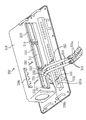
- FIG. 6 is a diagram illustrating a work method for inserting the cable 253 of the laser scanner 112 into the relay box 200 according to the first embodiment.
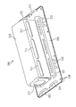
- FIG. FIG. 4 is a bottom view of relay box 200 in the first embodiment.
- FIG. The figure which shows the state which attached the relay box 200 in Embodiment 1 to the top plate 103 of the measurement vehicle 100.
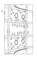
- FIG. FIG. 3 shows a top plate 103 viewed from the inside of the measurement vehicle 100 in the first embodiment.
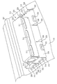
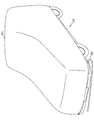
- FIG. 3 is a three-side view of the box cover 262 in the first embodiment.
- FIG. 6 is an external view showing a state in which cover poles 310f, 310m, and 310r are attached to measurement vehicle 100 in the second embodiment.
- the elements on larger scale which show the state which attached the cover pole 310f * 310m * 310r to the measurement vehicle 100 in Embodiment 2.
- FIG. FIG. 3 is a three-side view of the box cover 262 in the first embodiment.
- FIG. 6 is an external view showing a state in which cover poles 310f, 310m, and 310r are attached to measurement vehicle 100 in the second embodiment.
- the elements on larger scale which show the state which attached the cover pole 310f * 310m * 310r to the measurement vehicle 100 in Embodiment 2.
- FIG. 6 is an external view showing a state in which a vehicle cover 301 is put on a measurement vehicle 100 to which a cover pole 310 according to Embodiment 2 is attached. The figure which shows the method of removing the vehicle cover 301 from the measurement vehicle 100 in Embodiment 2.
- FIG. FIG. 6 is an external view showing a state where a cover pole 310 is removed from a measurement vehicle 100 according to a second embodiment. The figure which shows cover pole 310A * B in Embodiment 2.
- FIG. The side view of the roof rail installation base 320f * 320m * 320r in Embodiment 2.
- FIG. 10 is a partial plan view of measurement vehicle 100 showing the installation positions of roof rail installation base 320 and magnet installation base 330 in the second embodiment.
- Embodiment 1 A wiring box for collecting the cables of the mobile mapping system (MMS) sensor will be described.
- the wiring box of the present embodiment may be used for a vehicle other than the vehicle used in MMS.
- a mobile mapping system is a vehicle with a measuring instrument (sensor) such as a laser scanner, camera, positioning device, etc., which runs on a road, surveys the road and its surroundings using data acquired by running the vehicle, and This is a system for generating a three-dimensional map (see, for example, Patent Documents 1 and 2).
- FIG. 1 is an external view showing a measurement vehicle 100 of the mobile mapping system in the first embodiment.
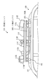
- FIG. 2 is a side view showing relay box 200 installed in measurement vehicle 100 in the first embodiment.
- the measurement vehicle 100 in Embodiment 1 is demonstrated based on FIG. 1 and FIG.
- a measurement vehicle 100 (an example of a vehicle) is a vehicle equipped with a measurement unit 110 and an odometer 120.
- the measurement unit 110 (sensor table, an example of sensor unit) includes six cameras 111A-111F, four laser scanners 112A-112D, and three GPS receivers 113A-113C (GPS: Global Positioning System).
- One IMU 114 Internal Measurement Unit
- the measurement unit 110 may include a different number of measurement devices from those in FIG.
- the cameras 111A-F are devices that capture an image of the periphery of the measurement vehicle 100.
- the camera 111A images the right front of the measurement vehicle 100
- the camera 111B images the left front of the measurement vehicle 100.
- the camera 111C images the right side of the measuring vehicle 100
- the camera 111D images the left side of the measuring vehicle 100.
- the camera 111E images the right rear of the measurement vehicle 100
- the camera 111F images the left rear of the measurement vehicle 100.
- the laser scanners 112A-D are apparatuses that irradiate laser light and measure the distance and direction to the point (measurement point) where the laser light is irradiated.
- the laser scanner 112 ⁇ / b> A measures the front lower side of the measurement vehicle 100
- the laser scanner 112 ⁇ / b> B measures the rear upper side of the measurement vehicle 100.
- the laser scanner 112 ⁇ / b> C measures the upper front side of the measurement vehicle 100
- the laser scanner 112 ⁇ / b> D measures the lower rear side of the measurement vehicle 100.
- the GPS receivers 113A-C are devices that perform positioning based on an antenna that receives a positioning signal from a positioning satellite and a reception result.
- GPS is an example of a positioning system (GNSS: Global Navigation Satellite Systems).
- the GPS receivers 113A-C may be receivers that use positioning systems other than GPS (such as GLONASS: Global Navigation Satellite System, Galileo, Quasi-Zenith Satellite System, etc.).
- the IMU 114 is a device (gyro sensor and acceleration sensor) that measures angular velocities in three axial directions (X, Y, Z).
- the odometer 120 is a device that measures the traveling speed of the measurement vehicle 100.
- the measurement unit 110 is installed on a roof carrier 102 attached to the roof rail 101 of the measurement vehicle 100.
- the relay box 200 is disposed between the measurement unit 110 and the top plate of the measurement vehicle 100 and collects cables of the measurement devices.
- FIG. 3 is a perspective view showing two relay boxes 200L and 200R installed on top plate 103 of measurement vehicle 100 in the first embodiment.
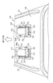
- FIG. 4 is a plan view showing two relay boxes 200L and 200R installed on top plate 103 of measurement vehicle 100 in the first embodiment. The arrangement of the two relay boxes 200 in the first embodiment will be described with reference to FIG. 3 and FIG.
- the relay box 200 is installed in the left portion and the right portion with respect to the traveling direction of the measurement vehicle 100 in the portion of the top plate 103 from behind the measurement vehicle 100.
- the relay box 200 may be installed in the front part or the central part of the measurement vehicle 100.
- the number of relay boxes 200 may be one or three or more.
- the plurality of relay boxes 200 may be arranged in front of each other instead of left and right.
- the relay box 200 installed in the left portion of the measurement vehicle 100 is referred to as “relay box 200L”
- the relay box 200 installed in the right portion of the measurement vehicle 100 is referred to as “relay box 200R”.
- the relay box 200 ⁇ / b> L / R includes a box-shaped main body part 210 and a flange part 220 surrounding the main body part 210.
- the main body 210 of the relay box 200L has three horizontally long slots (not shown) arranged side by side on the side surface arranged on the left side, and one large-diameter round hole 212 on the side surface arranged on the rear side. .
- the bottom of the main body 210 is open (not shown).
- the main body 210 of the relay box 200R has three horizontally long slots (not shown) side by side on the side surface arranged on the right side, and one large-diameter round hole 212 on the side surface arranged on the rear side. .
- the bottom of the main body 210 is open (not shown).
- the long holes may be provided on the opposite side surface or the left and right side surfaces, and the number of the long holes may be one, two, four or more, one instead of the long hole.
- a plurality of round holes may be provided.
- the round hole 212 may be provided on the front side surface or the front and rear side surfaces. Applications of the long hole and the round hole 212 will be described later.
- the flange portion 220 of the relay box 200L • R includes a cable receiving piece 221 on the side of the main body portion 210 where the elongated hole is provided, and a total of eight handle brackets 222 on the front, rear, left and right of the main body portion 210.
- one or more handle metal fittings 222 may be provided on each of the front, rear, left and right sides of the main body 210.
- the number (for example, two) of the handle fittings 222 provided for each may be different. Applications of the cable receiving piece 221 and the handle fitting 222 will be described later.
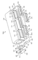
- FIG. 5 is an exploded view of relay box 200R in the first embodiment.
- Relay box 200R in the first embodiment will be described with reference to FIG.
- the relay box 200 ⁇ / b> R includes a box-shaped main body 210 and a flange 220 that surrounds the main body 210.
- the main body 210 of the relay box 200 ⁇ / b> R has three horizontally long holes 211 arranged side by side on the side surface arranged toward the right side of the measurement vehicle 100, and 1 on the side surface arranged toward the rear side of the measurement vehicle 100. Two large-diameter round holes 212 are provided. The bottom of the main body 210 is open (not shown).
- a grommet plate 230 is attached to the long hole 211 of the main body 210.
- the grommet plate 230 has four or five insertion holes 231 for inserting a cable of the measuring device.
- the number of insertion holes 231 provided in the grommet plate 230 may be one, two to three, or six or more.
- a ring-shaped grommet 232 is attached to each insertion hole 231 of the grommet plate 230 to prevent water from entering the main body 210 and cable damage.
- a sheet-like (or plate-like) packing 233 is provided between the periphery of the long hole 211 of the main body 210 and the grommet plate 230.
- the packing 233 has a long hole 234 that is approximately the same size as the long hole 211 of the main body 210.
- the main body 210 and the packing 233 may have a plurality of round holes in the same manner as the grommet plate 230 instead of the long holes 234.
- a plate-like grommet plate 240 is attached to the round hole 212 of the main body 210.
- the grommet plate 240 has an insertion hole 241 for inserting the cable of the laser scanner 112.
- a ring-shaped grommet 242 is attached to the insertion hole 241 of the grommet plate 240 for preventing water from entering the main body 210 and preventing cable breakage.
- a sheet-like (or plate-like) packing 243 is provided between the periphery of the round hole 212 of the main body 210 and the grommet plate 240.
- the packing 243 has a round hole 244 having the same size as the round hole 212 of the main body 210.
- the flange portion 220 of the relay box 200R includes a cable receiving piece 221 on the side where the elongated hole 211 of the main body 210 is provided, and a total of eight handle brackets 222, two on the front, rear, left, and right sides of the main body 210.
- the collar part 220 has a plurality of positioning holes 223 for positioning the relay box 200 ⁇ / b> R on the top plate 103 of the measurement vehicle 100.
- the cable receiving piece 221 is an L-shaped plate-shaped component that is inclined from the flange portion 220 toward the long hole 211, and the cable of the measuring device that is laid on the top plate 103 of the measurement vehicle 100 is a long hole that extends from below to above. Lead to 211.
- the cable receiving piece 221 has a plurality of fixing holes 221a for attaching a binding band for fixing the cable of the measuring device.
- the handle fitting 222 is used for fixing a box cover to be put on the relay box 200 and fixing a cable of the laser scanner 112 to be inserted into the insertion hole 241 of the grommet plate 240.
- the configuration of the relay box 200L is the same as the configuration of the relay box 200R shown in FIG. However, the long hole 211 and the cable receiving piece 221 of the relay box 200L are arranged on the side opposite to the relay box 200R (the left side of the measurement vehicle 100).
- FIG. 6 is an assembly diagram of relay box 200R in the first embodiment. A state after assembly of relay box 200R in the first embodiment will be described with reference to FIG. However, the state after the relay box 200L is assembled is the same as the state after the relay box 200R is assembled.
- a cable 250 of a measuring device is inserted into the grommet plate 230 attached to the main body 210 of the relay box 200R, and the cable 250 is fixed to the cable receiving piece 221 by a binding band 251.
- the protective tube 250a for example, corrugated tube
- the cut end of the protective tube 250a is protected by an adhesive tape 252 (for example, butyl rubber tape) so that the clothing of the cable 250 is not torn at the cut end of the protective tube 250a.
- the cable 253 of the laser scanner 112 is inserted into the grommet plate 240 attached to the main body 210 of the relay box 200R, and the cable 253 is fixed to the handle fitting 222 by a binding band 251.
- relay box 200 when it is not necessary to distinguish between the relay box 200R and the relay box 200L, they are simply referred to as “relay box 200”.
- FIG. 7 is a diagram illustrating an operation method for inserting the cable 253 of the laser scanner 112 into the relay box 200 according to the first embodiment. An operation method for inserting the cable 253 of the laser scanner 112 into the relay box 200 in the first embodiment will be described with reference to FIG.
- the laser scanner 112 includes a switch 254 having a diameter larger than that of the cable 253 at the tip of the cable 253.
- the operator attaches the packing 243 to the relay box 200 in alignment with the round hole 212, and inserts the switch 254 of the laser scanner 112 into the round hole 212 of the relay box 200.
- the grommet 242 has a notch and a fitting hole. The operator inserts the cable 253 into the fitting hole from the notch of the grommet 242.
- the grommet plate 240 includes an upper plate 240a and a lower plate 240b that are combined vertically.
- the upper plate 240 a has a semicircular cutout that forms the upper half of the insertion hole 241
- the lower plate 240 b has a semicircular cutout that forms the lower half of the insertion hole 241.
- the operator sandwiches the grommet 242 fitted with the cable 253 from above and below by the notch of the upper plate 240a and the notch of the lower plate 240b. Then, the operator fixes the upper plate 240a and the lower plate 240b with screws 255.
- the operator fixes the grommet plate 240 in which the grommet 242 attached to the cable 253 is disposed in the insertion hole 241 to the side surface of the relay box 200 having the round hole 212 with the screw 255.
- the operator fixes the cable 253 to the handle fitting 222 with the binding band 251.
- the grommet plate 240 may not be divided vertically by the upper plate 240a and the lower plate 240b, but may be divided by the left plate and the right plate. Further, the grommet plate 240 may be divided into three or more.
- FIG. 8 is a diagram illustrating a working method for inserting the cable 250 of the measuring device into the relay box 200 according to the first embodiment. An operation method for inserting the cable 250 of the measuring device into the relay box 200 in the first embodiment will be described with reference to FIG.
- the work method of inserting the cable 250 of the measuring device into the relay box 200 is the same as the work method of inserting the cable 253 of the laser scanner 112 into the relay box 200 (see FIG. 7).
- the operator inserts the cable 250 of the measuring device into the relay box 200 as follows.
- the operator attaches the packing 233 to the relay box 200 in alignment with the long hole 211, and inserts the cable 250 of the measuring device into the long hole 211 of the relay box 200.
- the operator attaches a grommet 232 having a notch to the cable 250.
- the operator holds the grommet 232 between the notch of the upper plate 230 a and the notch of the lower plate 230 b, and fixes the upper plate 230 a and the lower plate 230 b to the relay box 200 with screws 255.
- the operator passes the binding band 251 (not shown) through the fixing hole 221 a of the cable receiving piece 221 and fixes the cable 250 to the cable receiving piece 221 with the binding band 251.
- the grommet plate 230 may be divided into left and right, or may be divided into three or more.
- the relay box 200 is in a state as shown in FIG. 6.
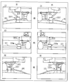
- FIG. 9 is a bottom view of relay box 200 in the first embodiment. As shown in FIG. 9, the bottom of the main body 210 of the relay box 200 is open. An operator applies the sealing agent 256 to a gap in the relay box 200 such as a joint between the main body part 210 and the flange part 220.
- FIG. 10 is a diagram showing a lead-in hole 103a opened in the top plate 103 of the measurement vehicle 100 in the first embodiment.
- the operator opens two lead-in holes 103a in the top plate 103 of the measuring vehicle 100 for one relay box 200 (see (1) in FIG. 10).
- An operator attaches a flexible ring-shaped grommet 257 (also referred to as a universal bush) to the pull-in hole 103a, and adheres the grommet 257 to the top plate 103 with an adhesive from the inside of the vehicle (see (2) in FIG. 10). .
- a flexible ring-shaped grommet 257 also referred to as a universal bush
- the operator determines the position for opening the lead-in hole 103a as follows.
- An operator writes a vehicle center line as a reference line using a tape or the like at the left and right center of the measuring vehicle 100, and uses a tape or the like as a reference line at the boundary between the rear door and the top plate 103 of the measuring vehicle 100.
- the operator drills a reference hole (rivet hole) at a position that is a predetermined first dimension away from the vehicle center line and the rear boundary line, and a predetermined size at a position that is a predetermined second dimension away from the reference hole.
- the lead-in hole 103a is opened.
- FIG. 11 is a diagram illustrating an operation method for positioning the relay box 200 in the first embodiment on the top plate 103 of the measurement vehicle 100.
- the operator forms a plurality of rivet holes in the top plate 103 of the measuring vehicle 100, attaches rivets 258 to the respective rivet holes, and inserts the plurality of rivets 258 into the plurality of positioning holes 223 to position the relay box 200 (FIG. 11).
- the operator drills a plurality of rivet holes in the top plate 103 of the measurement vehicle 100 as follows.
- An operator writes a vehicle center line as a reference line using a tape or the like at the left and right center of the measuring vehicle 100, and uses a tape or the like as a reference line at the boundary between the rear door and the top plate 103 of the measuring vehicle 100.
- the operator drills a reference rivet hole at a position separated from the vehicle center line and the rear boundary line by a predetermined first dimension, and attaches the reference rivet 258 to the reference rivet hole.
- the operator inserts the reference rivet 258 into a predetermined positioning hole 223 of the relay box 200 and adjusts the orientation of the relay box 200 around the reference rivet 258 as an axis.
- the operator makes a rivet hole in a portion of the relay box 200 where the remaining positioning holes 223 are arranged.
- FIG. 12 is a diagram illustrating a state in which the relay box 200 according to Embodiment 1 is attached to the top plate 103 of the measurement vehicle 100.
- the operator caulks each rivet 258 by pressing each rivet 258 (see FIG. 11) positioning the relay box 200 from above.
- the operator applies the sealing agent 256 to the edge portion of the flange portion 220 and the rivet 258 portion of the relay box 200 (see FIG. 12).
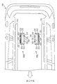
- FIG. 13 is a diagram illustrating the top plate 103 viewed from the inside of the measurement vehicle 100 according to the first embodiment. However, it is the state which peeled off the interior sheet in the vehicle and exposed the inner surface of the top plate 103. The operator applies the sealing agent 256 from the inside of the measuring vehicle 100 to the rivet 258 portion of the top plate 103 (see FIG. 13).
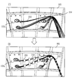
- FIG. 14 is a diagram illustrating a plurality of cables 250 drawn into the measurement vehicle 100 according to the first embodiment. However, it is the state which peeled off the interior sheet in the vehicle and exposed the inner surface of the top plate 103. As shown in FIG. 6, the operator connects cables 250 (including the cable 253 of the laser scanner 112. The same applies hereinafter) of a plurality of measuring devices inserted into the relay box 200 from the lead-in holes 103 a of the top plate 103 of the measuring vehicle 100. A plurality of cables 250 drawn into the vehicle are bundled together with a binding band 251 (see (1) in FIG. 14).
- the operator fixes the unbundled drawn portions of the plurality of cables 250 to the inner surface of the top plate 103 with an adhesive tape 259 (for example, a gum tape and a double-sided tape), and masking tape 260 on the portion of the plurality of cables 250 bundled. Are wrapped together to bundle a plurality of cables 250 together.
- an adhesive tape 259 for example, a gum tape and a double-sided tape
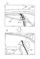
- FIG. 15 is a diagram illustrating a cable 250 that is drawn into the measurement vehicle 100 according to the first embodiment and integrated into the vehicle.
- the worker attaches the interior sheet 261 to the measurement vehicle 100 through the cable 250 integrated in the wiring hole 261a provided in the interior sheet 261 in the vehicle (see (1) and (2) in FIG. 15).
- the cables 250 of the plurality of measuring devices can be drawn into the measuring vehicle 100 from the relay box 200.
- FIG. 16 is a diagram illustrating a state in which the box cover 262 is put on the relay box 200 according to the first embodiment. As shown in FIG. 16, the effect of preventing inundation of the measuring vehicle 100 into the vehicle can be enhanced by covering the relay box 200 (see FIG. 6) with a box cover 262 (for example, a canvas cover made of vinylon).
- a box cover 262 for example, a canvas cover made of vinylon.
- FIG. 17 is a three-side view of the box cover 262 in the first embodiment. As shown in FIG. 17, two belts 262 a are provided on the front, rear, left, and right surfaces of the box cover 262. The operator puts the box cover 262 on the main body 210 of the relay box 200 and fixes the belts 262a of the box cover 262 to the handle fitting 222 in the flange 220 of the relay box 200 (see FIG. 16).
- the cables of the measurement device are randomly routed on the top plate 103 of the measurement vehicle 100.
- the box cover 262, the cable receiving piece 221 or the sealing agent 256 can prevent rainwater from flowing into the measuring vehicle 100 from the relay box 200 via the cable.
- the cable receiving piece 221 of the relay box 200 by fixing the middle part of the cable laid over the top plate 103 of the measurement vehicle 100 to the cable receiving piece 221 of the relay box 200 and inserting the tip of the cable into the elongated hole 211 of the relay box 200, rainwater It can be prevented from flowing into the relay box 200 through the cable. That is, according to Embodiment 1, a high waterproof effect can be obtained.
- the relay box 200 is disposed between the top plate 103 of the vehicle (measuring vehicle 100) and a sensor base (measuring unit 110) that has a sensor (measuring device) and is attached to the roof carrier 102 of the vehicle.
- the relay box 200 includes a main body portion (main body portion 210) having an insertion side portion provided with insertion holes (insertion holes 231 and insertion holes 241) into which the sensor cables are inserted, and an open bottom portion. And a collar part (a collar part 220) provided around the bottom of the opening.
- the flange portion 220 is fixed around a top plate hole (retraction hole 103 a) provided in the top plate 103. The cable is inserted into the vehicle body from the top plate hole that is inserted into the main body from the insertion hole and located at the bottom of the opening.
- the insertion side portion is configured by attaching a plate (grommet plate 230, grommet plate 240) having the insertion hole to a side surface provided with side holes (long holes 211, round holes 212) among the side surfaces of the main body portion. .
- the plate is configured by combining a plurality of plate parts (upper plate 230a / lower plate 230b, upper plate 240a / lower plate 240b) having notches constituting a part of the insertion hole.
- the plate is composed of an upper plate component (upper plate 230a, upper plate 240a) and a lower plate component (lower plate 230b, lower plate 230b) that are combined vertically as the plurality of plate components.
- the upper plate part has a semicircular cutout constituting the upper half of the insertion hole as the cutout.
- the lower plate component has a semicircular cutout constituting the lower half of the insertion hole as the cutout.
- the insertion side portion includes grommets (grommets 232 and grommets 242) having fitting holes for fitting the cables and notches for fitting the cables into the fitting holes.
- grommet the cable is inserted into the fitting hole from the notch, and is arranged in the insertion hole by being sandwiched by the notch portions of the plurality of plate parts.
- the insertion side portion includes packing (packing 233, packing 243) sandwiched between the plate and the side surface of the main body portion.
- the main body portion has a first insertion side portion as the insertion side portion on a first side surface facing the front and rear of the vehicle among the side surfaces of the main body portion, and the vehicle among the side surfaces of the main body portion.
- a second insertion side portion as the insertion side portion is provided on the second side surface facing either the left or right side of the.
- the first insertion side portion has one insertion hole (insertion hole 241) as the insertion hole.
- the second insertion side portion has a plurality of insertion holes (insertion holes 231) as the insertion holes.
- the flange portion of the main body portion includes a cable receiving piece (cable receiving piece 221) which is inclined toward the insertion hole on the insertion side portion side and guides the cable from the lower side to the upper insertion hole.
- the cable receiving piece has a fixing hole (fixing hole 221a) for attaching a fixing tool (binding band 251) for fixing the cable.
- the cable is fixed to the cable receiving piece by the fixing tool attached to the fixing hole of the cable receiving piece.
- the flange portion of the main body includes a plurality of attachments (handle fittings 222) for attaching a box cover (box cover 262) that covers the wiring box on the periphery.
- the collar portion of the main body includes a plurality of handles (handle fittings 222) as the plurality of attachments.
- a plurality of belts (belt 262a) included in the box cover are fixed to the plurality of attachments having a handle shape.
- FIG. A mode in which the measuring device of the measuring unit 110 is prevented from being displaced by the vehicle cover when the measuring vehicle 100 is covered with the vehicle cover will be described.
- the measurement vehicle 100, the measurement unit 110, and the relay box 200 are the same as those in the first embodiment.
- FIG. 18 is an external view showing a state in which cover poles 310f, 310m, and 310r are attached to measurement vehicle 100 in the second embodiment.
- FIG. 19 is a partially enlarged view showing a state where cover poles 310f, 310m, and 310r are attached to measurement vehicle 100 in the second embodiment.
- the cover pole 310 attached to the measurement vehicle 100 in the second embodiment will be described with reference to FIGS.
- the cover pole 310 is a component used for covering the measurement vehicle 100 with a vehicle cover.
- cover poles 310 are attached to the left, right roof rails 101 of the measurement vehicle 100 at the front portion, the middle portion, and the rear portion, respectively.
- the front portion cover pole 310f is attached while being inclined forward
- the intermediate portion cover pole 310m is attached directly upward
- the rear portion N cover pole 310r is attached inclined backward.
- each cover pole 310 is attached to the roof rail installation base 320 so that the measuring device (particularly the GPS receivers 113 ⁇ / b> A and 113 ⁇ / b> B) does not protrude outward from each cover pole 310 when viewed from the front and rear of the measurement vehicle 100. .
- the measuring device protrudes outward from each cover pole 310, the position and posture of the measuring device may be adjusted, or each cover pole 310 may be attached so as to be inclined outward.
- the roof rail installation base 320 will be described later.
- FIG. 20 is an external view illustrating a state in which the vehicle cover 301 is put on the measurement vehicle 100 to which the cover pole 310 according to the second embodiment is attached.
- the measurement vehicle 100 (see FIG. 18) to which the cover pole 310 is attached is covered with the vehicle cover 301, so that the measurement vehicle 100 is covered with the vehicle cover 301 lifted.
- the vehicle cover 301 does not contact the measuring device, and the position and posture of the measuring device are not shifted by the vehicle cover 301.
- the operator puts the vehicle cover 301 on the measurement vehicle 100 the operator should be careful not to cause the vehicle cover 301 to hit the measurement device and shift the position or posture of the measurement device. For example, the worker carefully puts the vehicle cover 301 on the measurement vehicle 100 using a stepladder.
- the vehicle cover 301 includes cover strings 302 at the front and rear. The worker fixes the vehicle cover 301 to the measurement vehicle 100 using the cover string 302 so that the vehicle cover 301 is not blown by the wind.
- FIG. 21 is a diagram illustrating a method of removing the vehicle cover 301 from the measurement vehicle 100 according to the second embodiment.
- the operator When removing the vehicle cover 301 from the measurement vehicle 100, the operator unwinds the cover string 302 of the vehicle cover 301 and collects the vehicle cover 301 in the center of the measurement vehicle 100 (see FIG. 21). Then, the worker removes the vehicle cover 301 by slowly pulling the vehicle cover 301 from the front (or rear) of the measurement vehicle 100. At this time, the worker is careful not to catch the vehicle cover 301 on the measuring device.
- the operator removes the vehicle cover 301 while adjusting the position of the vehicle cover 301. The operator may use a stepladder as necessary.
- FIG. 22 is an external view showing a state where the cover pole 310 is removed from the measurement vehicle 100 according to the second embodiment.
- the cover pole 310 is unnecessary and is removed from the roof rail installation base 320 (see FIG. 22).
- the roof rail installation base 320 will be described later.
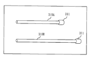
- FIG. 23 is a diagram showing cover poles 310A and B in the second embodiment.
- the cover poles 310A and 310B are cylindrical parts.
- a cap 311 is attached to the tip of each cover pole 310 ⁇ / b> A / B so that the vehicle cover 301 can be easily detached from the measurement vehicle 100.
- the longer cover pole 310A is used as cover poles 310f and 310r that are attached to the front and rear portions of the roof rail 101 of the measuring vehicle 100.
- the shorter cover pole 310B is used as a cover pole 310m that is attached to an intermediate portion of the roof rail 101 of the measurement vehicle 100.
- the length of the cover pole 310A is about 60 centimeters
- the length of the cover pole 310B is about 45 centimeters.
- the length of the cover poles 310A and B is longer as the measuring instrument is larger.
- FIG. 24 is a side view of roof rail installation bases 320f, 320m, and 320r in the second embodiment.
- the roof rail installation base 320 in Embodiment 2 is demonstrated based on FIG.
- the roof rail installation base 320 f of (1) is a component installed on the front side portion of the roof rail 101.
- the roof rail installation base 320m of (2) is a component installed in the middle part of the roof rail 101.
- the roof rail installation base 320r is a component installed on the rear side portion of the roof rail 101.
- Each roof rail installation base 320 includes a base main body 321 fixed to the roof rail 101 and a base pole 322 into which the cover pole 310 is fitted.
- the base pole 322 may be formed of a cylindrical member, and the cover pole 310 may be inserted into the base pole 322.
- the base body 321 is divided into an upper body 321a and a lower body 321b.
- the base body 321 is fixed to the roof rail 101 by sandwiching the roof rail 101 from above and below between the upper body 321a and the lower body 321b and connecting the upper body 321a and the lower body 321b with screws 323.
- the base pole 322 of the roof rail installation base 320f of (1) is inclined forward and upward.
- the base pole 322 of the roof rail installation base 320m of (2) is upward.
- the base pole 322 of the roof rail installation base 320r in (3) is inclined rearward and upward.
- FIG. 25 is a front view of roof rail installation base 320f ⁇ r in the second embodiment.
- the roof rail installation base 320f and the roof rail installation base 320r have installation holes 321c for sandwiching the roof rail 101 between the upper body 321a and the lower body 321b.
- the roof rail installation base 320m has an installation hole 321c (not shown).
- the outer shape of the base body 321 of the roof rail installation base 320f may be different from the outer shape of the base body 321 of the roof rail installation base 320r.
- the corner of the lower body 321b of the roof rail installation base 320r may be rounded from the corner of the lower body 321b of the roof rail installation base 320f (see FIG. 25).
- FIG. 26 is a partially enlarged view showing a state where roof rail installation base 320 is installed in measurement vehicle 100 in the second embodiment.
- the roof rail installation base 320 installed in the measurement vehicle 100 in Embodiment 2 will be described based on FIG.
- the roof rail installation base 320f is installed on the front side portion of the roof rail 101.
- the direction of the base pole 322 of the roof rail installation base 320f is front upward.
- the cover pole 310f can be tilted forward and upward.
- the roof rail installation base 320m is installed at an intermediate portion of the roof rail 101.
- the direction of the base pole 322 of the roof rail installation base 320m is upward.
- the cover pole 310 can be attached upward.
- the roof rail installation base 320r is installed in the rear portion of the roof rail 101.
- the direction of the base pole 322 of the roof rail installation base 320r is upward rearward.
- the measurement vehicle 100 is in the state shown in FIG.
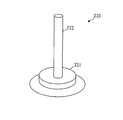
- FIG. 27 is a diagram illustrating a magnet installation base 330 according to the second embodiment.
- the magnet installation base 330 in Embodiment 2 is demonstrated based on FIG.
- the magnet installation base 330 includes a sucker-like base body 331 having a magnet and a base pole 332 into which the cover pole 310 is fitted.
- the base pole 332 may be formed of a cylindrical member, and the cover pole 310 may be inserted into the base pole 332.
- the magnet installation base 330 is fixed to the top plate 103 of the measurement vehicle 100 by the magnetic attraction force of the base body 331.
- the longer cover pole 310A (see FIG. 23) is attached to the base pole 332 of the magnet installation base 330.
- the magnet installation base 330 is used when the measurement vehicle 100 is covered with the vehicle cover 301 and is removed when the measurement vehicle 100 is traveled.
- FIG. 28 is a partial plan view of measurement vehicle 100 showing the installation positions of roof rail installation base 320 and magnet installation base 330 in the second embodiment.
- a dotted circle frame indicates a position where the roof rail installation base 320 is installed
- a bold circle frame indicates a position where the magnet installation base 330 is installed.
- the position where the magnet installation base 330 is installed is preferably closer to the central portion of the measurement unit 110.
- the magnet installation base 330 may be installed in any gap portion of the measurement unit 110.
- Embodiment 2 for example, the following cover pole unit (part group, part set, system) has been described.
- the cover pole unit is for covering a vehicle (measurement vehicle 100) with a vehicle cover (vehicle cover 301).
- the cover pole unit includes a first installation base (roof rail installation base 320) installed at the front of the left roof rail of the left and right roof rails (roof rail 101) of the vehicle, and a first installation base attached to the first installation base.
- the cover pole unit includes a second installation base installed at a front portion of the right roof rail among the left and right roof rails, and a second cover pole attached to the second installation base.
- the cover pole unit includes a third installation base installed at an intermediate portion of the left roof rail, and a third cover pole attached to the third installation base.
- the cover pole unit includes a fourth installation base installed at an intermediate portion of the right roof rail, and a fourth cover pole attached to the fourth installation base.
- the cover pole unit includes a fifth installation base installed on the rear portion of the left roof rail, and a fifth cover pole attached to the fifth installation base.
- the cover pole unit includes a sixth installation base installed on the rear portion of the right roof rail, and a sixth cover pole attached to the sixth installation base. The vehicle cover covers the first to sixth cover poles.
- the first installation base includes a first base body (base body 321) that is fixed to the front portion of the left roof rail, and a first pole attachment portion that is attached by tilting the first cover pole forward and upward.
- Base pole 322 The second installation base includes a second base body that is fixed to the front portion of the right roof rail, and a second pole attachment portion that is attached by tilting the second cover pole forward and upward.
- the third installation base includes a third base body that is fixed to the intermediate portion of the left roof rail, and a third pole attachment portion that attaches the third cover pole upward.
- the fourth installation base includes a fourth base body that is fixed to the intermediate portion of the right roof rail, and a fourth pole mounting portion that mounts the fourth cover pole upward.
- the fifth installation base includes a fifth base body that is fixed to the rear portion of the left roof rail, and a fifth pole attachment portion that attaches the fifth cover pole upward and rearward.
- the sixth installation base includes a sixth base body that is fixed to the rear portion of the right roof rail, and a sixth pole attachment portion that attaches the sixth cover pole upward and rearward.
- the first to sixth cover poles are cylindrical bars.
- the first pole mounting portion is a bar member that is inclined forward and upward, and the first cover pole is fitted into the first pole mounting portion.
- the second pole mounting portion is a bar member that is inclined forward and upward, and the second cover pole is fitted into the second pole mounting portion.
- the third pole mounting portion is an upward-facing bar, and the third cover pole is fitted into the third pole mounting portion.
- the fourth pole mounting part is an upward-facing bar, and the fourth cover pole is fitted into the fourth pole mounting part.
- the fifth pole mounting portion is a bar member inclined upward and rearward, and the fifth cover pole is fitted into the fifth pole mounting portion.
- the sixth pole mounting portion is a bar member tilted rearward and upward, and the sixth cover pole is fitted into the sixth pole mounting portion.
- the cover pole unit includes a seventh installation base (magnet installation base 330) disposed between the left roof rail and the right roof rail, and a seventh cover pole (cover) attached to the seventh installation base. Pole 310).
- the seventh installation base is fixed to the top plate of the vehicle with a magnet.
- the vehicle cover covers the first to seventh cover poles.
Landscapes
- Engineering & Computer Science (AREA)
- Architecture (AREA)
- Civil Engineering (AREA)
- Structural Engineering (AREA)
- Mechanical Engineering (AREA)
- Length Measuring Devices By Optical Means (AREA)
- Connection Or Junction Boxes (AREA)
Abstract
Priority Applications (4)
| Application Number | Priority Date | Filing Date | Title |
|---|---|---|---|
| PCT/JP2012/057511 WO2013140603A1 (fr) | 2012-03-23 | 2012-03-23 | Boîtier de câblage et unité de protection de perche d'accrochage |
| JP2014505930A JP5823021B2 (ja) | 2012-03-23 | 2012-03-23 | 配線ボックス |
| KR1020147028587A KR101582129B1 (ko) | 2012-03-23 | 2012-03-23 | 배선 박스 |
| KR1020157036352A KR101611891B1 (ko) | 2012-03-23 | 2012-03-23 | 커버 폴 유닛 |
Applications Claiming Priority (1)
| Application Number | Priority Date | Filing Date | Title |
|---|---|---|---|
| PCT/JP2012/057511 WO2013140603A1 (fr) | 2012-03-23 | 2012-03-23 | Boîtier de câblage et unité de protection de perche d'accrochage |
Publications (1)
| Publication Number | Publication Date |
|---|---|
| WO2013140603A1 true WO2013140603A1 (fr) | 2013-09-26 |
Family
ID=49222097
Family Applications (1)
| Application Number | Title | Priority Date | Filing Date |
|---|---|---|---|
| PCT/JP2012/057511 Ceased WO2013140603A1 (fr) | 2012-03-23 | 2012-03-23 | Boîtier de câblage et unité de protection de perche d'accrochage |
Country Status (3)
| Country | Link |
|---|---|
| JP (1) | JP5823021B2 (fr) |
| KR (2) | KR101611891B1 (fr) |
| WO (1) | WO2013140603A1 (fr) |
Cited By (4)
| Publication number | Priority date | Publication date | Assignee | Title |
|---|---|---|---|---|
| WO2016167109A1 (fr) * | 2015-04-14 | 2016-10-20 | 住友電装株式会社 | Structure d'étanchéité pour unité de commande électronique |
| GB2570458A (en) * | 2018-01-24 | 2019-07-31 | Jaguar Land Rover Ltd | Mounting module for a vehicle |
| WO2019153314A1 (fr) * | 2018-02-12 | 2019-08-15 | 四川行之智汇知识产权运营有限公司 | Système de commande de protection intelligent pour une sécurité de caisse de véhicule |
| JP2020178501A (ja) * | 2019-04-22 | 2020-10-29 | 富士電機株式会社 | 電力変換装置 |
Families Citing this family (1)
| Publication number | Priority date | Publication date | Assignee | Title |
|---|---|---|---|---|
| CA3176241A1 (fr) * | 2020-05-13 | 2021-11-18 | GAF Energy LLC | Passe-cable electrique |
Citations (9)
| Publication number | Priority date | Publication date | Assignee | Title |
|---|---|---|---|---|
| US4655236A (en) * | 1985-07-02 | 1987-04-07 | Elizabeth S. Dorame | Portable carport |
| JPS6351825U (fr) * | 1986-09-24 | 1988-04-07 | ||
| JPS6397421A (ja) * | 1986-10-10 | 1988-04-28 | Shotaro Ueno | 自動車の防熱防霜装置 |
| JPS6450119U (fr) * | 1987-09-25 | 1989-03-28 | ||
| JPH05520U (ja) * | 1991-06-24 | 1993-01-08 | ブレーンエンジニアリング株式会社 | 自動車用日除け装置 |
| JP2002034055A (ja) * | 2000-07-13 | 2002-01-31 | Ryosuke Shibazaki | 移動体用広視野角多方向画像取得装置及び移動体用広視野角多方向画像取得システム |
| JP2003226346A (ja) * | 2001-11-30 | 2003-08-12 | Yazaki Corp | 電子部品収納箱の防水構造 |
| US20060086470A1 (en) * | 2004-10-26 | 2006-04-27 | Muniza Ghazali | Collapsible car sun shade |
| JP2010175423A (ja) * | 2009-01-30 | 2010-08-12 | Mitsubishi Electric Corp | 計測装置、計測装置のレーザー位置姿勢値補正方法およびレーザー位置姿勢値補正プログラム |
Family Cites Families (6)
| Publication number | Priority date | Publication date | Assignee | Title |
|---|---|---|---|---|
| US5918898A (en) * | 1996-02-15 | 1999-07-06 | Trw Vehicle Safety Systems Inc. | Side impact air bag module |
| JP2003011735A (ja) | 2001-06-28 | 2003-01-15 | Auto Network Gijutsu Kenkyusho:Kk | 車載用電子機器ユニット |
| EP3112802B1 (fr) | 2007-02-16 | 2019-10-09 | Mitsubishi Electric Corporation | Appareil de mesure de caractéristique d'une route et procédé de mesure de caractéristique d'une route |
| US7494348B1 (en) | 2007-08-01 | 2009-02-24 | Tyco Electronics Corporation | Cable termination apparatus and method |
| DE102008022049B4 (de) | 2008-05-03 | 2010-07-15 | Lumberg Connect Gmbh | Anschlussdose zur Anbindung eines Solarmoduls |
| KR101269981B1 (ko) | 2008-08-29 | 2013-05-31 | 미쓰비시덴키 가부시키가이샤 | 부감 화상 생성장치, 부감 화상 생성방법 및 기록매체 |
-
2012
- 2012-03-23 KR KR1020157036352A patent/KR101611891B1/ko not_active Expired - Fee Related
- 2012-03-23 KR KR1020147028587A patent/KR101582129B1/ko not_active Expired - Fee Related
- 2012-03-23 WO PCT/JP2012/057511 patent/WO2013140603A1/fr not_active Ceased
- 2012-03-23 JP JP2014505930A patent/JP5823021B2/ja not_active Expired - Fee Related
Patent Citations (9)
| Publication number | Priority date | Publication date | Assignee | Title |
|---|---|---|---|---|
| US4655236A (en) * | 1985-07-02 | 1987-04-07 | Elizabeth S. Dorame | Portable carport |
| JPS6351825U (fr) * | 1986-09-24 | 1988-04-07 | ||
| JPS6397421A (ja) * | 1986-10-10 | 1988-04-28 | Shotaro Ueno | 自動車の防熱防霜装置 |
| JPS6450119U (fr) * | 1987-09-25 | 1989-03-28 | ||
| JPH05520U (ja) * | 1991-06-24 | 1993-01-08 | ブレーンエンジニアリング株式会社 | 自動車用日除け装置 |
| JP2002034055A (ja) * | 2000-07-13 | 2002-01-31 | Ryosuke Shibazaki | 移動体用広視野角多方向画像取得装置及び移動体用広視野角多方向画像取得システム |
| JP2003226346A (ja) * | 2001-11-30 | 2003-08-12 | Yazaki Corp | 電子部品収納箱の防水構造 |
| US20060086470A1 (en) * | 2004-10-26 | 2006-04-27 | Muniza Ghazali | Collapsible car sun shade |
| JP2010175423A (ja) * | 2009-01-30 | 2010-08-12 | Mitsubishi Electric Corp | 計測装置、計測装置のレーザー位置姿勢値補正方法およびレーザー位置姿勢値補正プログラム |
Cited By (6)
| Publication number | Priority date | Publication date | Assignee | Title |
|---|---|---|---|---|
| WO2016167109A1 (fr) * | 2015-04-14 | 2016-10-20 | 住友電装株式会社 | Structure d'étanchéité pour unité de commande électronique |
| GB2570458A (en) * | 2018-01-24 | 2019-07-31 | Jaguar Land Rover Ltd | Mounting module for a vehicle |
| GB2570458B (en) * | 2018-01-24 | 2020-08-05 | Jaguar Land Rover Ltd | Mounting module for a vehicle |
| WO2019153314A1 (fr) * | 2018-02-12 | 2019-08-15 | 四川行之智汇知识产权运营有限公司 | Système de commande de protection intelligent pour une sécurité de caisse de véhicule |
| JP2020178501A (ja) * | 2019-04-22 | 2020-10-29 | 富士電機株式会社 | 電力変換装置 |
| JP7263900B2 (ja) | 2019-04-22 | 2023-04-25 | 富士電機株式会社 | 電力変換装置 |
Also Published As
| Publication number | Publication date |
|---|---|
| KR101611891B1 (ko) | 2016-04-14 |
| JPWO2013140603A1 (ja) | 2015-08-03 |
| KR20140142286A (ko) | 2014-12-11 |
| KR101582129B1 (ko) | 2016-01-04 |
| KR20160005131A (ko) | 2016-01-13 |
| JP5823021B2 (ja) | 2015-11-25 |
Similar Documents
| Publication | Publication Date | Title |
|---|---|---|
| JP5823021B2 (ja) | 配線ボックス | |
| US10207646B2 (en) | Vehicle front camera module integrated with rearview mirror | |
| CN107618450B (zh) | 自主车辆传感器总成的车顶安装 | |
| US10118369B2 (en) | Laminated glazing unit | |
| TWI634314B (zh) | Measuring device | |
| JP5647376B2 (ja) | 建設機械用衛星アンテナ固定装置 | |
| KR20110109774A (ko) | 차량탑재 악세사리의 고정구, 및 상기 고정구에 의한 차량탑재 악세사리의 장착 방법 | |
| GB0706521D0 (en) | Unmanned airborne vehicle for geophysical surveying | |
| EP1247706A3 (fr) | Structure d'installation d'un dispositif anti-vol pour une motocyclette | |
| JP6922706B2 (ja) | センサー搭載構造 | |
| ATE428608T1 (de) | Omnidirektionaler crashsensor | |
| US10557729B2 (en) | Sensor mounting structure | |
| JP2019099046A (ja) | センサー搭載構造 | |
| US8291551B2 (en) | Clamp assembly | |
| JP2019099048A (ja) | センサー搭載構造 | |
| JP6985330B2 (ja) | スライド装置、及び、スライド装置用の発光装置 | |
| JP2003309410A (ja) | 車両用埋込みアンテナの搭載構造および車両用埋込みアンテナの搭載方法 | |
| JP2020077586A (ja) | 保護カバーおよび車載用装置 | |
| JP6509471B1 (ja) | 計測装置 | |
| WO2016117405A1 (fr) | Structure d'identification de faisceau de câbles | |
| CN109278662A (zh) | 车载adas装置 | |
| KR101347863B1 (ko) | 기준점 측량을 위한 관측지역의 삼각점간 gps 관측시스템 | |
| JP6852646B2 (ja) | インストルメントパネルの取付構造 | |
| JP6771762B2 (ja) | 機器 | |
| JPH11301363A (ja) | 車両の車載機器用アンテナ取付構造 |
Legal Events
| Date | Code | Title | Description |
|---|---|---|---|
| 121 | Ep: the epo has been informed by wipo that ep was designated in this application |
Ref document number: 12872191 Country of ref document: EP Kind code of ref document: A1 |
|
| ENP | Entry into the national phase |
Ref document number: 2014505930 Country of ref document: JP Kind code of ref document: A |
|
| NENP | Non-entry into the national phase |
Ref country code: DE |
|
| ENP | Entry into the national phase |
Ref document number: 20147028587 Country of ref document: KR Kind code of ref document: A |
|
| 122 | Ep: pct application non-entry in european phase |
Ref document number: 12872191 Country of ref document: EP Kind code of ref document: A1 |