WO2013140653A1 - Procédé de traitement de gaz de refoulement - Google Patents
Procédé de traitement de gaz de refoulement Download PDFInfo
- Publication number
- WO2013140653A1 WO2013140653A1 PCT/JP2012/077935 JP2012077935W WO2013140653A1 WO 2013140653 A1 WO2013140653 A1 WO 2013140653A1 JP 2012077935 W JP2012077935 W JP 2012077935W WO 2013140653 A1 WO2013140653 A1 WO 2013140653A1
- Authority
- WO
- WIPO (PCT)
- Prior art keywords
- exhaust gas
- water
- alkaline electrolyzed
- strong alkaline
- electrolyzed water
- Prior art date
- Legal status (The legal status is an assumption and is not a legal conclusion. Google has not performed a legal analysis and makes no representation as to the accuracy of the status listed.)
- Ceased
Links
Images

Classifications
-
- B—PERFORMING OPERATIONS; TRANSPORTING
- B01—PHYSICAL OR CHEMICAL PROCESSES OR APPARATUS IN GENERAL
- B01D—SEPARATION
- B01D53/00—Separation of gases or vapours; Recovering vapours of volatile solvents from gases; Chemical or biological purification of waste gases, e.g. engine exhaust gases, smoke, fumes, flue gases, aerosols
- B01D53/34—Chemical or biological purification of waste gases
- B01D53/96—Regeneration, reactivation or recycling of reactants
-
- B—PERFORMING OPERATIONS; TRANSPORTING
- B01—PHYSICAL OR CHEMICAL PROCESSES OR APPARATUS IN GENERAL
- B01D—SEPARATION
- B01D53/00—Separation of gases or vapours; Recovering vapours of volatile solvents from gases; Chemical or biological purification of waste gases, e.g. engine exhaust gases, smoke, fumes, flue gases, aerosols
- B01D53/34—Chemical or biological purification of waste gases
- B01D53/346—Controlling the process
-
- B—PERFORMING OPERATIONS; TRANSPORTING
- B01—PHYSICAL OR CHEMICAL PROCESSES OR APPARATUS IN GENERAL
- B01D—SEPARATION
- B01D53/00—Separation of gases or vapours; Recovering vapours of volatile solvents from gases; Chemical or biological purification of waste gases, e.g. engine exhaust gases, smoke, fumes, flue gases, aerosols
- B01D53/34—Chemical or biological purification of waste gases
- B01D53/74—General processes for purification of waste gases; Apparatus or devices specially adapted therefor
- B01D53/77—Liquid phase processes
-
- B—PERFORMING OPERATIONS; TRANSPORTING
- B01—PHYSICAL OR CHEMICAL PROCESSES OR APPARATUS IN GENERAL
- B01D—SEPARATION
- B01D53/00—Separation of gases or vapours; Recovering vapours of volatile solvents from gases; Chemical or biological purification of waste gases, e.g. engine exhaust gases, smoke, fumes, flue gases, aerosols
- B01D53/34—Chemical or biological purification of waste gases
- B01D53/74—General processes for purification of waste gases; Apparatus or devices specially adapted therefor
- B01D53/77—Liquid phase processes
- B01D53/78—Liquid phase processes with gas-liquid contact
-
- B—PERFORMING OPERATIONS; TRANSPORTING
- B01—PHYSICAL OR CHEMICAL PROCESSES OR APPARATUS IN GENERAL
- B01D—SEPARATION
- B01D53/00—Separation of gases or vapours; Recovering vapours of volatile solvents from gases; Chemical or biological purification of waste gases, e.g. engine exhaust gases, smoke, fumes, flue gases, aerosols
- B01D53/34—Chemical or biological purification of waste gases
- B01D53/96—Regeneration, reactivation or recycling of reactants
- B01D53/965—Regeneration, reactivation or recycling of reactants including an electrochemical process step
-
- B—PERFORMING OPERATIONS; TRANSPORTING
- B05—SPRAYING OR ATOMISING IN GENERAL; APPLYING FLUENT MATERIALS TO SURFACES, IN GENERAL
- B05B—SPRAYING APPARATUS; ATOMISING APPARATUS; NOZZLES
- B05B14/00—Arrangements for collecting, re-using or eliminating excess spraying material
- B05B14/40—Arrangements for collecting, re-using or eliminating excess spraying material for use in spray booths
- B05B14/46—Arrangements for collecting, re-using or eliminating excess spraying material for use in spray booths by washing the air charged with excess material
- B05B14/462—Arrangements for collecting, re-using or eliminating excess spraying material for use in spray booths by washing the air charged with excess material and separating the excess material from the washing liquid, e.g. for recovery
-
- B—PERFORMING OPERATIONS; TRANSPORTING
- B01—PHYSICAL OR CHEMICAL PROCESSES OR APPARATUS IN GENERAL
- B01D—SEPARATION
- B01D2251/00—Reactants
- B01D2251/30—Alkali metal compounds
- B01D2251/306—Alkali metal compounds of potassium
-
- B—PERFORMING OPERATIONS; TRANSPORTING
- B01—PHYSICAL OR CHEMICAL PROCESSES OR APPARATUS IN GENERAL
- B01D—SEPARATION
- B01D2252/00—Absorbents, i.e. solvents and liquid materials for gas absorption
- B01D2252/10—Inorganic absorbents
- B01D2252/103—Water
-
- B—PERFORMING OPERATIONS; TRANSPORTING
- B01—PHYSICAL OR CHEMICAL PROCESSES OR APPARATUS IN GENERAL
- B01D—SEPARATION
- B01D2257/00—Components to be removed
- B01D2257/70—Organic compounds not provided for in groups B01D2257/00 - B01D2257/602
- B01D2257/708—Volatile organic compounds V.O.C.'s
-
- B—PERFORMING OPERATIONS; TRANSPORTING
- B01—PHYSICAL OR CHEMICAL PROCESSES OR APPARATUS IN GENERAL
- B01D—SEPARATION
- B01D2258/00—Sources of waste gases
- B01D2258/02—Other waste gases
- B01D2258/025—Other waste gases from metallurgy plants
-
- B—PERFORMING OPERATIONS; TRANSPORTING
- B01—PHYSICAL OR CHEMICAL PROCESSES OR APPARATUS IN GENERAL
- B01D—SEPARATION
- B01D2258/00—Sources of waste gases
- B01D2258/02—Other waste gases
- B01D2258/0258—Other waste gases from painting equipments or paint drying installations
-
- B—PERFORMING OPERATIONS; TRANSPORTING
- B01—PHYSICAL OR CHEMICAL PROCESSES OR APPARATUS IN GENERAL
- B01D—SEPARATION
- B01D2258/00—Sources of waste gases
- B01D2258/02—Other waste gases
- B01D2258/0266—Other waste gases from animal farms
-
- B—PERFORMING OPERATIONS; TRANSPORTING
- B01—PHYSICAL OR CHEMICAL PROCESSES OR APPARATUS IN GENERAL
- B01D—SEPARATION
- B01D2258/00—Sources of waste gases
- B01D2258/02—Other waste gases
- B01D2258/0275—Other waste gases from food processing plants or kitchens
-
- B—PERFORMING OPERATIONS; TRANSPORTING
- B01—PHYSICAL OR CHEMICAL PROCESSES OR APPARATUS IN GENERAL
- B01D—SEPARATION
- B01D53/00—Separation of gases or vapours; Recovering vapours of volatile solvents from gases; Chemical or biological purification of waste gases, e.g. engine exhaust gases, smoke, fumes, flue gases, aerosols
- B01D53/34—Chemical or biological purification of waste gases
- B01D53/38—Removing components of undefined structure
- B01D53/40—Acidic components
-
- Y—GENERAL TAGGING OF NEW TECHNOLOGICAL DEVELOPMENTS; GENERAL TAGGING OF CROSS-SECTIONAL TECHNOLOGIES SPANNING OVER SEVERAL SECTIONS OF THE IPC; TECHNICAL SUBJECTS COVERED BY FORMER USPC CROSS-REFERENCE ART COLLECTIONS [XRACs] AND DIGESTS
- Y02—TECHNOLOGIES OR APPLICATIONS FOR MITIGATION OR ADAPTATION AGAINST CLIMATE CHANGE
- Y02P—CLIMATE CHANGE MITIGATION TECHNOLOGIES IN THE PRODUCTION OR PROCESSING OF GOODS
- Y02P70/00—Climate change mitigation technologies in the production process for final industrial or consumer products
- Y02P70/10—Greenhouse gas [GHG] capture, material saving, heat recovery or other energy efficient measures, e.g. motor control, characterised by manufacturing processes, e.g. for rolling metal or metal working
Definitions
- the present invention relates to a method for treating exhaust gas discharged from a painting process or the like.
- a method in which the exhaust gas is passed through a caustic soda solution or the like and removed by a neutralization reaction is generally performed.
- countermeasures against bad odor of exhaust gas include cleaning methods, adsorption methods, combustion methods, condensation methods, biological deodorization methods, ozone deodorization methods, photocatalytic deodorization methods, plasma deodorization methods, and deodorizing / deodorizing agent methods.
- the target exhaust gas is extremely diverse, but livestock farming. Fertilizer and feed production plant. Grocery factory. Rubber factory. Painting and printing factory. Woodworking factory. Foundry. Garbage disposal site. Human waste treatment plant. Meat market. Composting facility. Septic tank. Cleaning factory. Countermeasures for bad odor have become a problem for exhaust gas discharged from these companies such as restaurants.
- Odor generation from exhaust gas is complicated by the process, and there are many cases where countermeasures by the above-mentioned method are difficult, and the problem has not yet been solved.
- exhaust gas from the baking process at high temperatures is difficult to remove bad odors, and complaints and troubles from the surrounding area are constantly occurring, which is going to be a problem that shakes the foundation of business continuity for painters.
- the cleaning method is used in many fields, and is particularly suitable for removing odors of single components such as animal and plant rotten odors and chemical factories, but is generally suitable for removing organic solvent odors and burnt odors. It is said that there is no.
- the cleaning method has been used alone, but it is often used in combination with other deodorization methods, and a method for deodorizing high-concentration odors by a cleaning method and an adsorption method (see Patent Document 1) is well known. ing.
- a method for deodorizing high-concentration odors by a cleaning method and an adsorption method is well known.
- pre-processing of a deodorizing apparatus it is often used for the purposes of gas cooling, humidification, dust and mist collection.
- proper operation management and maintenance are important to ensure the target deodorizing performance in any deodorizing method and deodorizing apparatus.
- many methods are known for the countermeasure against malodor of various exhaust gases, but there are various problems.
- the so-called wet cleaning methods such as the conventional chemical charging method and watering shower method are methods in which exhaust gas is passed through a caustic soda solution, etc., and is removed by a neutralization reaction. It was necessary to use it by dissolving it in water, and equipment management and labor were costly.
- the present invention can solve such a conventional problem, a method for removing malodor from various exhaust gases other than automobile exhaust gases, that is, livestock farming. Fertilizer and feed production plant. Grocery factory. Rubber factory. Painting and printing factory. Woodworking factory. Foundry. Garbage disposal site. Human waste treatment plant. Meat market. Composting facility. Septic tank. Cleaning factory. It aims at providing the method of removing the malodor from the waste gas discharged
- the means for solving the problems of the present invention are specifically as follows. (1) In an exhaust gas treatment apparatus using water containing strong alkaline electrolyzed water, the exhaust gas is brought into direct contact with water containing strong alkaline electrolyzed water and having a pH of 9 or more and an ORP of 0 mV or less. An exhaust gas treatment method. (2) Strong alkaline electrolyzed water having a pH of 9.5 or more and an ORP of 0 mV to -960 mV is added to water containing strong alkaline electrolyzed water after contacting exhaust gas, and the PH is 9 or more. And the ORP is water kept at 0 mV or less, and the water is circulated and reused.
- An exhaust gas treatment apparatus for carrying out the exhaust gas treatment method according to any one of (1) to (6) above, wherein the storage tank (1) stores water containing strong alkaline electrolyzed water
- An exhaust gas treatment apparatus comprising: a contact / mixing unit that directly contacts and mixes exhaust gas introduced into the water containing strong alkaline electrolyzed water stored in the storage tank (1). .
- a slight gap (3) is formed on the surface of the water containing strong alkaline electrolyzed water stored in the tank (1) and placed on the storage tank (1).
- the contact / mixing section is composed of a shower nozzle (20) for spraying water containing strong alkaline electrolyzed water stored in the storage tank (1) through a pump (19).
- (11) From the duct (23) in which the contact / mixing part introduces and bubbles an air flow (16) in which exhaust gas is put on water containing strong alkaline electrolyzed water stored in the storage tank (1).
- the exhaust gas deodorization method of the present invention is intended for all the above-mentioned various exhaust gases other than automobile exhaust gases. Fertilizer and feed production plant. Grocery factory. Rubber factory. Painting and printing factory. Woodworking factory. Foundry. Garbage disposal site. Human waste treatment plant. Meat market. Composting facility. Septic tank. Cleaning factory. It is effective as a method for deodorizing exhaust gas from a company process such as a restaurant, or exhaust gas from a painting process, particularly a baking painting process. Below, it demonstrates taking the case of the deodorizing method of the waste gas from a baking painting process as an example.
- the odor in the baking coating process depends mainly on the paint component (organic component alone or a mixture of organic and inorganic components) contained in the exhaust gas, the solvent, and the aldehyde component (specified by the Malodor Control Law) generated in the process. ing.
- the water containing strong alkaline electrolyzed water absorbs the temperature of the high temperature exhaust gas and lowers the temperature. Has also been found to be very effective removal.
- the exhaust gas is brought into contact with water containing strong alkaline electrolyzed water and having a pH of 9 or more and an ORP of 0 mV or less, and the paint component (the organic component alone or the organic component in the exhaust gas) And a mixture of inorganic components) are precipitated and separated.
- the exhaust gas is directly contacted at high speed with water containing strong alkaline electrolyzed water and having a pH of 9 or more and an ORP of 0 mV or less, and the mixture is forcedly stirred and mixed. It is particularly effective to deposit and separate components alone or a mixture of organic and inorganic components.
- a coating component (an organic component alone or a mixture of an organic component and an inorganic component) is precipitated and separated from the exhaust gas, and at the same time, the malodor of the exhaust gas is completely removed.
- the aldehyde which is one of the causes of bad odor in the exhaust gas is polymerized by aldol condensation reaction when treated with water containing the alkaline electrolyzed water. It is estimated that the odor is removed by being incorporated into the precipitate.
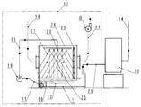
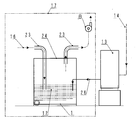
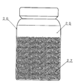
- generation apparatus The figure which shows an example of the shower type exhaust gas processing apparatus which concerns on another embodiment of this invention. The figure which shows an example of the bubbling type exhaust gas processing apparatus which concerns on another embodiment of this invention. The figure which shows the precipitation state of a deposit.
- the present inventor uses strongly alkaline electrolyzed water to which exhaust gas is collected, water having a pH of 9 or more and an ORP of 0 mV or less, particularly in the case of exhaust gas from a baking coating process.
- the present invention has been completed by finding a treatment method in which a coating component (a single organic component or a mixture of an organic component and an inorganic component) is precipitated from the inside, and the malodor of exhaust gas is completely removed.
- a coating component a single organic component or a mixture of an organic component and an inorganic component
- the water containing strong alkaline electrolyzed water that contacts exhaust gas has a pH of 9 or more, preferably 11 or more, and most preferably 12 or more.
- the upper limit of PH is about 14, and it is possible to use up to this level of PH.
- the ORP should be 0 mV or less, preferably 0 mV to -960 mV, more preferably -200 mV to -960 mV.
- PH is a scale indicating the acidity / alkaliness of water
- ORP is a unit of redox potential.
- ORP is a unit of redox potential.
- a substance has an ORP of 0 mV or less, it has a reducing power, and when it exceeds 0 mV, it has an oxidizing power.
- the present inventor made measurements using a HM-30P type PH meter and an RM-30P type ORP meter manufactured by Toa DKK Corporation.
- the exhaust gas is sucked and collected by an exhaust fan (suction fan) (refer to 8 in FIG. 1), and reacts by being brought into contact with water containing strong alkaline electrolyzed water at high speed and colliding and stirred.
- a coating component an organic component alone or a mixture of an organic component and an inorganic component
- the exhaust gas and water containing strong alkaline electrolyzed water are directly contacted, but also the paint component (the organic component alone or the organic component and the inorganic component) This is desirable for precipitating and separating the mixture) and simultaneously removing malodors.
- the exhaust gas is collected in a high-speed air flow generated by an exhaust fan (suction fan) (see 8 in FIG. 1), and is preferably placed in a high-speed air flow of 10 m / second or more and contains strong alkaline electrolyzed water.
- an exhaust fan suction fan
- the exhaust gas contains fine particles composed of organic substances and inorganic fillers.
- This exhaust gas is an air flow (see 16 in FIG. 1) created by the exhaust fan (suction fan) (see 8 in FIG. 1) of the deodorizing device. Is pulled to the agitation and mixing unit (see 18 in FIG. 1), and is preferably caused by the action of a high-speed air flow of 30 m / second or more that occurs in the agitation and mixing unit (in this case, the air flow 16 has a narrow gap 3).
- the speed is increased when passing, and the turbulent flow is generated by the Reynolds effect and the negative pressure is generated to suck up the water containing the strong alkaline electrolyzed water), and the exhaust gas and the water containing the strong alkaline electrolyzed water are brought into direct contact with each other at high speed.
- the turbulent flow is generated by the Reynolds effect and the negative pressure is generated to suck up the water containing the strong alkaline electrolyzed water
- the exhaust gas and the water containing the strong alkaline electrolyzed water are brought into direct contact with each other at high speed.
- Strong alkaline electrolyzed water obtained with a normal strong alkaline electrolyzed water generator used in the present invention has a pH of 9.5 or more, an ORP of 0 mV to -960 mV, preferably a PH of 11 to 14, and an ORP of It needs to be -200 mV to -960 mV.
- the ORP may be ⁇ 960 mV or less. Strong alkaline electrolyzed water is produced (produced) by water and electricity, and its principle and production method are widely disclosed and well known.
- An electrolyte suitable as an electrolyte to be used for producing strong alkaline electrolyzed water is potassium carbonate, and this aqueous solution is used as raw water to be supplied to a strong alkaline electrolyzed water generator.
- potassium carbonate is used as an electrolyte, the generated strong alkaline electrolyzed water does not contain potassium carbonate. Since no chemically synthesized substances are contained, the values of BOD (biochemical oxygen demand), COD (chemical oxygen demand), N-hexane (oil content), and SS (floating substance) are zero.
- Strong alkaline electrolyzed water used in the present invention can be controlled independently for PH and ORP, and by having the specific PH and specific ORP, it has a large amount of electrons and strong intermolecular attractive force (electron peeling).
- the action has a bactericidal effect, and the amount of dissolved hydrogen is large and the amount of dissolved oxygen is small, so that the electrolytic water itself is prevented from decaying and has a deodorizing action.
- the temperature of the alkaline electrolyzed water is preferably 40 to 70 degrees, but may be 40 degrees or less. According to the exhaust gas treatment method of the present invention, it is possible to provide a better working environment and a surrounding environment without diffusing bad odors to the surrounding environment.
- the coating component the organic component alone or the mixture of the organic component and the inorganic component
- the separated component can be used as a secondary material such as cement after drying.
- the melamine-based resin baking paint exhaust gas (hereinafter simply referred to as exhaust gas) was maintained at a pH of 9.5 to 10 and an ORP of ⁇ 200 mV to ⁇ 960 mV, including strong alkaline electrolyzed water, using the exhaust gas treatment apparatus of FIG.
- exhaust gas When water was used for continuous treatment for 8 hours, the exhaust gas after treatment had a deodorizing effect such that no odor was felt.
- separated adhered a little to the vessel wall, it was collect
- the exhaust gas treatment apparatus of FIG. 1 will be described in detail.
- the exhaust gas treatment device 17 is roughly composed of a storage tank 1 and a scrubber that store circulating water 12 (water containing strong alkaline electrolyzed water and having a pH of 9.5 to 10 and an ORP of ⁇ 200 mV to ⁇ 960 mV). (Gas-liquid separator) 2 and a separation tank 9.
- the exhaust gas from the baking coating process rides on this air flow 16 and enters the scrubber (gas-liquid separator) 2 through a slight gap 3 formed by the lower end 5 of the scrubber (gas-liquid separator) 2 and the water surface of the circulating water 12.
- the airflow 16 becomes a high-speed airflow that reaches 10 meters / second or more when passing through the slight gap 3), and is reflected by a reflector 6 (or a spiral plate) provided in the vicinity of the gap 3.
- the high-speed air stream at a speed of 10 meters / second or more, the circulating water 12 and the exhaust gas are forcibly stirred and mixed while rotating strongly along the reflector 6 (or the spiral plate). .
- the circulating water 12 mixed with the exhaust gas carried by the high-speed air current collides with the collision plate 4 in the scrubber (gas-liquid separation device) 2, and the momentum decreases, and the paint component (the organic component alone, the organic component and the inorganic component) Circulated water 12 which collected the mixture of the water and the water falls as water droplets and flows from the dropping port 7 of the scrubber (gas-liquid separator) 2 to the separation tank 9.
- the exhaust gas from which an organic component or a mixture of organic and inorganic components (hereinafter referred to as sludge) is separated during the process is exhausted and discharged to the atmosphere by an exhaust fan (suction fan) 8.
- the separation tank 9 is provided with a weir 10.
- the weir 10 is attached to the bottom of the water tank 1, and the upper part is submerged by about 1/4 of the water depth from the water surface. For this reason, the sludge of the mixture of the organic component and the inorganic component having settled and gathered in front of the water flow is blocked by the weir 10, while the sludge of the light organic component having floated on the flow rides on the inner wall of the separation tank 9. To gather.
- a pipe 11 communicating with the storage tank 1 is provided downstream of the separation tank 9, and the water containing the strong alkaline electrolyzed water after the exhaust gas treatment is returned to the storage tank 1 to be used as the collection circulating water 12 again.
- the separation tank 9 the sludge having a high specific gravity denatured into a sediment remains on the weir 10, and the sludge having a low specific gravity denatured into a floating body remains on the inner wall surface of the separation tank 9 and is deposited automatically or manually. Discharge.
- the separation mechanism of the exhaust gas from the baking coating process by the water containing the strong alkaline electrolyzed water 26 is considered as follows. 1) An organic component alone or a mixture of an organic component and an inorganic component in exhaust gas from the baking coating process is attacked by water containing strong alkaline electrolyzed water 26 (that is, circulating water 12), and is deposited and separated from the exhaust gas. .
- the aldehyde that causes malodor in the exhaust gas is polymerized by the aldol condensation reaction when treated with water containing the alkaline electrolyzed water, and the odor is removed by being taken into the precipitate. It is estimated to be.
- the separation tank 9 near the outlet 7 of the scrubber (gas-liquid separation device) 2 was used.
- the circulating water 12 collected from near the bottom of each was observed, it was observed that it was deposited in a mixture of the organic component and the inorganic component to form a precipitate. (See Figure 4)
- Table 1 shows the measured metal content of sludge deposited from the exhaust gas from the baking coating process.
- Example 1 When treated in the same manner as in Example 1 except that the shower type exhaust gas treatment apparatus of FIG. 2 was used, a deodorizing effect was recognized such that the exhaust gas after treatment was slightly inferior to that of Example 1, but no odor was felt. . Moreover, although the coating component (mixture of the organic component and the inorganic component) which precipitated and isolate
- Example 2 Except that tap water was used instead of strong alkaline electrolyzed water, it was carried out as in Example 1. As a result, the precipitate was suspended, had an odor, and no deodorizing effect was observed. [Comparative Example 2] Except using water containing strong alkaline electrolyzed water and a pH of 9.5 to 10 and an ORP maintained at +200 mV, it was carried out as in Example 1. As a result, the precipitate was suspended, had an odor, and had a deodorizing effect. Was not recognized.
Landscapes
- Engineering & Computer Science (AREA)
- Chemical & Material Sciences (AREA)
- Environmental & Geological Engineering (AREA)
- Chemical Kinetics & Catalysis (AREA)
- Biomedical Technology (AREA)
- Analytical Chemistry (AREA)
- General Chemical & Material Sciences (AREA)
- Oil, Petroleum & Natural Gas (AREA)
- Health & Medical Sciences (AREA)
- Life Sciences & Earth Sciences (AREA)
- Sustainable Development (AREA)
- Electrochemistry (AREA)
- Treating Waste Gases (AREA)
- Gas Separation By Absorption (AREA)
- Separation Of Particles Using Liquids (AREA)
- Water Treatment By Electricity Or Magnetism (AREA)
Priority Applications (4)
| Application Number | Priority Date | Filing Date | Title |
|---|---|---|---|
| EP12872219.6A EP2835172A4 (fr) | 2012-03-23 | 2012-10-30 | Procédé de traitement de gaz de refoulement |
| US14/387,096 US20150064084A1 (en) | 2012-03-23 | 2012-10-30 | Method for Treating Discharge Gas |
| CN201280071734.8A CN104220146A (zh) | 2012-03-23 | 2012-10-30 | 废气处理方法 |
| KR1020147029050A KR20140145161A (ko) | 2012-03-23 | 2012-10-30 | 배기 가스의 처리 방법 |
Applications Claiming Priority (2)
| Application Number | Priority Date | Filing Date | Title |
|---|---|---|---|
| JP2012066578 | 2012-03-23 | ||
| JP2012-066578 | 2012-03-23 |
Publications (1)
| Publication Number | Publication Date |
|---|---|
| WO2013140653A1 true WO2013140653A1 (fr) | 2013-09-26 |
Family
ID=49222142
Family Applications (1)
| Application Number | Title | Priority Date | Filing Date |
|---|---|---|---|
| PCT/JP2012/077935 Ceased WO2013140653A1 (fr) | 2012-03-23 | 2012-10-30 | Procédé de traitement de gaz de refoulement |
Country Status (6)
| Country | Link |
|---|---|
| US (1) | US20150064084A1 (fr) |
| EP (1) | EP2835172A4 (fr) |
| JP (2) | JPWO2013140653A1 (fr) |
| KR (1) | KR20140145161A (fr) |
| CN (1) | CN104220146A (fr) |
| WO (1) | WO2013140653A1 (fr) |
Cited By (1)
| Publication number | Priority date | Publication date | Assignee | Title |
|---|---|---|---|---|
| JP2018103078A (ja) * | 2016-12-22 | 2018-07-05 | 住友金属鉱山株式会社 | 無害化装置及び無害化方法 |
Families Citing this family (11)
| Publication number | Priority date | Publication date | Assignee | Title |
|---|---|---|---|---|
| WO2015174854A1 (fr) * | 2014-05-16 | 2015-11-19 | Compac Technologies Limited | Goulotte d'acheminement en douceur |
| FR3040637A1 (fr) * | 2015-09-09 | 2017-03-10 | Xeda International | Procede de purification d'un flux de gaz charge en cov |
| KR101575699B1 (ko) * | 2015-11-02 | 2015-12-08 | 정재억 | 복합악취 제거설비 |
| WO2017119657A1 (fr) * | 2016-01-07 | 2017-07-13 | 주식회사 엘지화학 | Nouveau polyorganosiloxane et copolycarbonate préparé au moyen de celui-ci |
| CN108236837B (zh) * | 2017-04-21 | 2020-08-25 | 金广恒环保技术(南京)股份有限公司 | 一种含铬废气处理装置 |
| KR101965189B1 (ko) * | 2017-11-16 | 2019-04-05 | 한국에너지기술연구원 | 정전분무방식을 이용한 습식 집진 장치 |
| CN110292850A (zh) * | 2018-11-06 | 2019-10-01 | 杭州嘉苗农业开发有限公司 | 养殖场臭气处理净化设备 |
| KR102069379B1 (ko) * | 2019-07-23 | 2020-01-22 | 주식회사 이엠제이 | 오염공기 탈취장치 |
| JP6763535B1 (ja) * | 2020-05-29 | 2020-09-30 | 株式会社バイオアパタイト | 卵殻膜分離システム、及び卵殻膜分離方法 |
| KR102367590B1 (ko) * | 2021-05-14 | 2022-02-24 | 성원해 | 발효조용 분진 제거 장치 |
| KR102898965B1 (ko) * | 2022-12-23 | 2025-12-11 | 주식회사 신양 | 압력에 따라 유로의 폭을 변화시키는 포집 장치 |
Citations (8)
| Publication number | Priority date | Publication date | Assignee | Title |
|---|---|---|---|---|
| JPH04256413A (ja) * | 1991-02-05 | 1992-09-11 | Yoshio Ogino | 有機溶剤を含むガスの浄化装置および浄化方法 |
| JP2000157830A (ja) * | 1998-11-25 | 2000-06-13 | Kashiyama Kogyo Kk | 排ガス処理方法および処理装置 |
| JP2001259357A (ja) * | 2000-03-14 | 2001-09-25 | Tokai Univ | 廃ガスの処理方法およびその処理装置 |
| JP2004290713A (ja) * | 2001-12-28 | 2004-10-21 | Omega:Kk | 排気又は排煙の脱臭・浄化方法とその装置 |
| JP2006181503A (ja) * | 2004-12-28 | 2006-07-13 | Nissan Motor Co Ltd | 塗装ブース循環水の処理方法及び装置 |
| WO2008072392A1 (fr) * | 2006-12-15 | 2008-06-19 | Kanken Techno Co., Ltd. | Procédé de traitement de gaz de refoulement et appareil pour celui-ci |
| JP2010042353A (ja) * | 2008-08-12 | 2010-02-25 | Kinji Takeuchi | 脱臭装置 |
| JP2010075879A (ja) | 2008-09-26 | 2010-04-08 | Cs Engineering:Kk | 排ガスの脱臭処理方法 |
Family Cites Families (12)
| Publication number | Priority date | Publication date | Assignee | Title |
|---|---|---|---|---|
| JPS5120234A (en) * | 1974-05-31 | 1976-02-18 | Dainippon Toryo Kk | Suiseitoryomisutono kaishuhoho |
| JP3105957B2 (ja) * | 1991-09-11 | 2000-11-06 | サンエス工業株式会社 | 簡易塗装ブース |
| JP2749258B2 (ja) * | 1994-03-04 | 1998-05-13 | 英雄 早川 | 排ガス処理方法及びその装置 |
| DE60014831T2 (de) * | 1999-05-17 | 2005-10-13 | Mitsubishi Heavy Industries, Ltd. | Verfahren zur behandlung der abwässer einer abgasenentschwefelungsanlage |
| US7837877B2 (en) * | 2006-06-09 | 2010-11-23 | Air Products And Chemicals, Inc. | Process for separating components of a multi-component feed stream |
| US8425665B2 (en) * | 2007-01-19 | 2013-04-23 | Heartland Technology Partners, Llc | Fluid scrubber |
| US8574506B2 (en) * | 2007-02-21 | 2013-11-05 | Osaka Prefecture University Public Corporation | Method and apparatus for processing exhaust gas |
| JP4863404B2 (ja) * | 2008-08-22 | 2012-01-25 | 株式会社オメガ | スクラバー機構 |
| JP5247768B2 (ja) * | 2010-07-16 | 2013-07-24 | アネスト岩田株式会社 | ベンチュリー式水洗塗装ブースの渦巻室水槽 |
| JP2012120935A (ja) * | 2010-12-06 | 2012-06-28 | Uv Technica:Kk | 塗装ブース循環水の処理方法及び装置 |
| JP2012125720A (ja) * | 2010-12-16 | 2012-07-05 | Junichiro Sato | 脱臭装置 |
| CN103648661B (zh) * | 2011-07-08 | 2015-07-08 | 优威泰克株式会社 | 涂料喷雾的处理方法 |
-
2012
- 2012-10-30 WO PCT/JP2012/077935 patent/WO2013140653A1/fr not_active Ceased
- 2012-10-30 KR KR1020147029050A patent/KR20140145161A/ko not_active Withdrawn
- 2012-10-30 JP JP2013508059A patent/JPWO2013140653A1/ja active Pending
- 2012-10-30 US US14/387,096 patent/US20150064084A1/en not_active Abandoned
- 2012-10-30 CN CN201280071734.8A patent/CN104220146A/zh active Pending
- 2012-10-30 EP EP12872219.6A patent/EP2835172A4/fr not_active Withdrawn
-
2018
- 2018-09-05 JP JP2018179468A patent/JP2019013920A/ja active Pending
Patent Citations (8)
| Publication number | Priority date | Publication date | Assignee | Title |
|---|---|---|---|---|
| JPH04256413A (ja) * | 1991-02-05 | 1992-09-11 | Yoshio Ogino | 有機溶剤を含むガスの浄化装置および浄化方法 |
| JP2000157830A (ja) * | 1998-11-25 | 2000-06-13 | Kashiyama Kogyo Kk | 排ガス処理方法および処理装置 |
| JP2001259357A (ja) * | 2000-03-14 | 2001-09-25 | Tokai Univ | 廃ガスの処理方法およびその処理装置 |
| JP2004290713A (ja) * | 2001-12-28 | 2004-10-21 | Omega:Kk | 排気又は排煙の脱臭・浄化方法とその装置 |
| JP2006181503A (ja) * | 2004-12-28 | 2006-07-13 | Nissan Motor Co Ltd | 塗装ブース循環水の処理方法及び装置 |
| WO2008072392A1 (fr) * | 2006-12-15 | 2008-06-19 | Kanken Techno Co., Ltd. | Procédé de traitement de gaz de refoulement et appareil pour celui-ci |
| JP2010042353A (ja) * | 2008-08-12 | 2010-02-25 | Kinji Takeuchi | 脱臭装置 |
| JP2010075879A (ja) | 2008-09-26 | 2010-04-08 | Cs Engineering:Kk | 排ガスの脱臭処理方法 |
Non-Patent Citations (1)
| Title |
|---|
| See also references of EP2835172A4 |
Cited By (1)
| Publication number | Priority date | Publication date | Assignee | Title |
|---|---|---|---|---|
| JP2018103078A (ja) * | 2016-12-22 | 2018-07-05 | 住友金属鉱山株式会社 | 無害化装置及び無害化方法 |
Also Published As
| Publication number | Publication date |
|---|---|
| EP2835172A4 (fr) | 2015-11-11 |
| US20150064084A1 (en) | 2015-03-05 |
| EP2835172A1 (fr) | 2015-02-11 |
| JP2019013920A (ja) | 2019-01-31 |
| CN104220146A (zh) | 2014-12-17 |
| JPWO2013140653A1 (ja) | 2015-08-03 |
| KR20140145161A (ko) | 2014-12-22 |
Similar Documents
| Publication | Publication Date | Title |
|---|---|---|
| JP2019013920A (ja) | 有機成分を含む塗料成分含有排ガスの処理装置 | |
| JP5286580B2 (ja) | 塗料スプレーミストの処理方法 | |
| CN108348847B (zh) | 复合恶臭去除设备 | |
| JP2004503367A (ja) | 海水の脱塩方法 | |
| CN101132994B (zh) | 废气废水处理装置以及废气废水处理方法 | |
| AU2001213118A1 (en) | Process for desalination of seawater | |
| CA2673301A1 (fr) | Systeme, composition, et procede d'absorption de gaz | |
| KR20120070562A (ko) | 도료 폐액 처리방법 | |
| CN106823716A (zh) | 清洁受污染空气流的方法和装置 | |
| JP4574640B2 (ja) | 塗料廃液分離装置及び塗料廃液分離方法 | |
| KR20100104991A (ko) | 멀티선회류 및 바이오 필터를 이용한 고효율 하이브리드 VOCs 습식처리 시스템 | |
| JP2014036926A (ja) | 排水浄化装置及び排水浄化方法 | |
| CN104128078B (zh) | 污泥储存池的除臭装置及除臭方法 | |
| KR102215310B1 (ko) | 고농도 황화수소를 제거하기 위한 철킬레이트 탈취기 | |
| CN204865428U (zh) | 一种废气处理装置 | |
| JP2005177552A (ja) | 塗装ブース水の処理剤と処理方法 | |
| JP4590481B2 (ja) | 湿式塗装ブース循環水の気泡による浮上分離浄化方法 | |
| CN200942327Y (zh) | 含油恶臭气体的治理装置 | |
| JP2008279368A (ja) | 排水の処理機構及び処理方法 | |
| JP2004074084A (ja) | 塗装ブースの汚水浄化システム | |
| CN208130800U (zh) | 微纳米气泡协同臭氧废气处理装置 | |
| KR101003268B1 (ko) | 폐수의 암모니아 처리장치 | |
| CN105289156A (zh) | 喷漆废气处理工艺 | |
| JP2008055397A (ja) | 塗装工程で生じる廃水の処理方法 | |
| JP6141656B2 (ja) | ナノミスト回収装置及びナノミスト回収方法 |
Legal Events
| Date | Code | Title | Description |
|---|---|---|---|
| ENP | Entry into the national phase |
Ref document number: 2013508059 Country of ref document: JP Kind code of ref document: A |
|
| 121 | Ep: the epo has been informed by wipo that ep was designated in this application |
Ref document number: 12872219 Country of ref document: EP Kind code of ref document: A1 |
|
| WWE | Wipo information: entry into national phase |
Ref document number: 14387096 Country of ref document: US |
|
| ENP | Entry into the national phase |
Ref document number: 20147029050 Country of ref document: KR Kind code of ref document: A |
|
| REEP | Request for entry into the european phase |
Ref document number: 2012872219 Country of ref document: EP |
|
| WWE | Wipo information: entry into national phase |
Ref document number: 2012872219 Country of ref document: EP |
|
| NENP | Non-entry into the national phase |
Ref country code: DE |