WO2013140693A1 - Dispositif plat à lampe - Google Patents
Dispositif plat à lampe Download PDFInfo
- Publication number
- WO2013140693A1 WO2013140693A1 PCT/JP2012/083422 JP2012083422W WO2013140693A1 WO 2013140693 A1 WO2013140693 A1 WO 2013140693A1 JP 2012083422 W JP2012083422 W JP 2012083422W WO 2013140693 A1 WO2013140693 A1 WO 2013140693A1
- Authority
- WO
- WIPO (PCT)
- Prior art keywords
- lamp device
- light
- translucent cover
- flat lamp
- light source
- Prior art date
- Legal status (The legal status is an assumption and is not a legal conclusion. Google has not performed a legal analysis and makes no representation as to the accuracy of the status listed.)
- Ceased
Links
Images


Classifications
-
- F—MECHANICAL ENGINEERING; LIGHTING; HEATING; WEAPONS; BLASTING
- F21—LIGHTING
- F21V—FUNCTIONAL FEATURES OR DETAILS OF LIGHTING DEVICES OR SYSTEMS THEREOF; STRUCTURAL COMBINATIONS OF LIGHTING DEVICES WITH OTHER ARTICLES, NOT OTHERWISE PROVIDED FOR
- F21V23/00—Arrangement of electric circuit elements in or on lighting devices
- F21V23/003—Arrangement of electric circuit elements in or on lighting devices the elements being electronics drivers or controllers for operating the light source, e.g. for a LED array
- F21V23/004—Arrangement of electric circuit elements in or on lighting devices the elements being electronics drivers or controllers for operating the light source, e.g. for a LED array arranged on a substrate, e.g. a printed circuit board
- F21V23/006—Arrangement of electric circuit elements in or on lighting devices the elements being electronics drivers or controllers for operating the light source, e.g. for a LED array arranged on a substrate, e.g. a printed circuit board the substrate being distinct from the light source holder
-
- F—MECHANICAL ENGINEERING; LIGHTING; HEATING; WEAPONS; BLASTING
- F21—LIGHTING
- F21K—NON-ELECTRIC LIGHT SOURCES USING LUMINESCENCE; LIGHT SOURCES USING ELECTROCHEMILUMINESCENCE; LIGHT SOURCES USING CHARGES OF COMBUSTIBLE MATERIAL; LIGHT SOURCES USING SEMICONDUCTOR DEVICES AS LIGHT-GENERATING ELEMENTS; LIGHT SOURCES NOT OTHERWISE PROVIDED FOR
- F21K9/00—Light sources using semiconductor devices as light-generating elements, e.g. using light-emitting diodes [LED] or lasers
- F21K9/20—Light sources comprising attachment means
-
- F—MECHANICAL ENGINEERING; LIGHTING; HEATING; WEAPONS; BLASTING
- F21—LIGHTING
- F21K—NON-ELECTRIC LIGHT SOURCES USING LUMINESCENCE; LIGHT SOURCES USING ELECTROCHEMILUMINESCENCE; LIGHT SOURCES USING CHARGES OF COMBUSTIBLE MATERIAL; LIGHT SOURCES USING SEMICONDUCTOR DEVICES AS LIGHT-GENERATING ELEMENTS; LIGHT SOURCES NOT OTHERWISE PROVIDED FOR
- F21K9/00—Light sources using semiconductor devices as light-generating elements, e.g. using light-emitting diodes [LED] or lasers
- F21K9/60—Optical arrangements integrated in the light source, e.g. for improving the colour rendering index or the light extraction
- F21K9/61—Optical arrangements integrated in the light source, e.g. for improving the colour rendering index or the light extraction using light guides
-
- F—MECHANICAL ENGINEERING; LIGHTING; HEATING; WEAPONS; BLASTING
- F21—LIGHTING
- F21V—FUNCTIONAL FEATURES OR DETAILS OF LIGHTING DEVICES OR SYSTEMS THEREOF; STRUCTURAL COMBINATIONS OF LIGHTING DEVICES WITH OTHER ARTICLES, NOT OTHERWISE PROVIDED FOR
- F21V5/00—Refractors for light sources
-
- F—MECHANICAL ENGINEERING; LIGHTING; HEATING; WEAPONS; BLASTING
- F21—LIGHTING
- F21V—FUNCTIONAL FEATURES OR DETAILS OF LIGHTING DEVICES OR SYSTEMS THEREOF; STRUCTURAL COMBINATIONS OF LIGHTING DEVICES WITH OTHER ARTICLES, NOT OTHERWISE PROVIDED FOR
- F21V7/00—Reflectors for light sources
- F21V7/0091—Reflectors for light sources using total internal reflection
Definitions
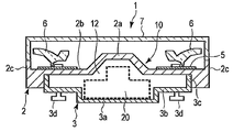
- the embodiment of the present invention relates to a flat lamp device having, for example, a GX53 type base.
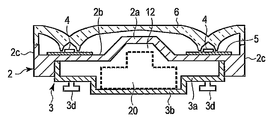
- the translucent cover 6 is formed in a substantially donut shape or ring shape by a transparent resin such as polycarbonate or acrylic.
- the translucent cover 6 is placed on the upper part of the base 2, the outer peripheral edge of the translucent cover 6 is on the upper surface of the side wall 2 c of the base 2, and the inner peripheral edge is on the side wall of the base 2 above the central convex part 2 a.
- Each is fixed.
- the translucent cover 6 has covered the light source 4, it is located in the same plane as the protrusion end surface of the center convex part 2a, and is following the protrusion end surface.
- the surface of the translucent cover 6 is formed with a texture to make it difficult to see wiring and the like through the inside.
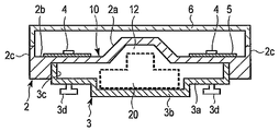
- the central convex portion 2a of the substrate 2 has a truncated cone shape, but is not particularly limited to this shape, and may be a cylindrical shape or a pyramid shape, and may not be a rotationally symmetric shape. Needless to say.
- the central convex portion 2 a of the main body 10 is constituted by the base 3, not the base material 2. That is, the base 3 includes a ceiling wall 14 having a central convex portion 2a formed of a synthetic resin.
- the ceiling wall 14 is disposed in the storage recess 12, and the central convex portion 2 a is inserted through the central opening of the base material 2 and protrudes forward.
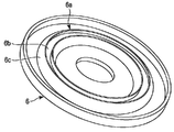
- the translucent cover 6 includes a protruding portion 6a protruding from the inner surface, a light intake portion 6b, and a side wall portion 6c, and a cross section of the protruding portion 6a.
- the shape is the same as that of the third embodiment.
- the protrusions 6a have a rotationally symmetric shape with the individual light sources 4 as the central axes, whereas in the fifth embodiment, the protrusions 6a have a central axis of the flat lamp device. On the other hand, it is formed in a rotationally symmetric shape.
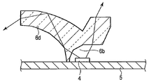
- FIG. 6A is a cross-sectional view showing a flat lamp device 1 according to a sixth embodiment.
- the basic configuration of the lamp device 1 is the same as that of the fourth embodiment, and the configuration of the translucent cover 6 is partially different.
- the taper angle of the outer peripheral surface of the side wall 6c is different from that of the fourth embodiment, and the opening angle between the inner peripheral surface and the outer peripheral surface is reduced.
- the translucent cover 6 configured as described above, light emitted from the light source 4 in a relatively lateral direction is not reflected by the outer peripheral surface of the side wall portion 6c, but is bent upward and emitted.
- FIG. 7C shows the light distribution of the flat lamp device 1.
- the translucent cover 6 irradiates a considerable amount of light from the side surface to the back side of the lamp device, so that a flat lamp device 1 with a wide light distribution can be realized.
Landscapes
- Engineering & Computer Science (AREA)
- General Engineering & Computer Science (AREA)
- Microelectronics & Electronic Packaging (AREA)
- Physics & Mathematics (AREA)
- Optics & Photonics (AREA)
- Non-Portable Lighting Devices Or Systems Thereof (AREA)
Abstract
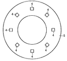
Selon un mode de réalisation de la présente invention, un dispositif plat à lampe comprend : un corps principal plat (10) comprenant en outre une partie saillante centrale (2a) qui est située au centre d'une partie face avant et dépasse vers le haut et une partie périphérique (2b) qui est située à la périphérie de la partie saillante centrale et est plus basse que la partie saillante centrale ; une pluralité de sources lumineuses (4) qui sont situées sur la partie périphérique du corps principal, et qui possèdent une distribution lumineuse à forte directivité dans les directions normales respectives associées ; un circuit de commande (20) qui est contenu dans le corps principal à l'intérieur de la partie saillante centrale ; et un couvercle transparent à la lumière (6) qui recouvre les sources lumineuses.
Applications Claiming Priority (2)
| Application Number | Priority Date | Filing Date | Title |
|---|---|---|---|
| JP2012-068407 | 2012-03-23 | ||
| JP2012068407A JP2013201016A (ja) | 2012-03-23 | 2012-03-23 | 扁平型ランプ装置 |
Publications (1)
| Publication Number | Publication Date |
|---|---|
| WO2013140693A1 true WO2013140693A1 (fr) | 2013-09-26 |
Family
ID=49222179
Family Applications (1)
| Application Number | Title | Priority Date | Filing Date |
|---|---|---|---|
| PCT/JP2012/083422 Ceased WO2013140693A1 (fr) | 2012-03-23 | 2012-12-25 | Dispositif plat à lampe |
Country Status (2)
| Country | Link |
|---|---|
| JP (1) | JP2013201016A (fr) |
| WO (1) | WO2013140693A1 (fr) |
Cited By (1)
| Publication number | Priority date | Publication date | Assignee | Title |
|---|---|---|---|---|
| JP2015072826A (ja) * | 2013-10-03 | 2015-04-16 | パナソニックIpマネジメント株式会社 | 照明装置 |
Families Citing this family (3)
| Publication number | Priority date | Publication date | Assignee | Title |
|---|---|---|---|---|
| JP2015220226A (ja) * | 2015-02-17 | 2015-12-07 | コイズミ照明株式会社 | 照明器具 |
| JP7050556B2 (ja) * | 2018-04-09 | 2022-04-08 | 三菱電機株式会社 | 光源ユニット及び照明装置 |
| JP7316631B2 (ja) * | 2019-02-22 | 2023-07-28 | パナソニックIpマネジメント株式会社 | 照明装置 |
Citations (10)
| Publication number | Priority date | Publication date | Assignee | Title |
|---|---|---|---|---|
| JPH0459166U (fr) * | 1990-09-25 | 1992-05-21 | ||
| JP3110293U (ja) * | 2005-02-09 | 2005-06-16 | 凱柏 陳 | 赤外線センサー付き電球 |
| JP2009021082A (ja) * | 2007-07-11 | 2009-01-29 | Sharp Corp | 照明装置 |
| JP2009032563A (ja) * | 2007-07-27 | 2009-02-12 | Tamura Seisakusho Co Ltd | 発光装置 |
| JP2010015798A (ja) * | 2008-07-03 | 2010-01-21 | Panasonic Corp | ランプ |
| JP2010062005A (ja) * | 2008-09-04 | 2010-03-18 | Panasonic Corp | ランプ |
| JP3169376U (ja) * | 2010-08-20 | 2011-07-28 | 旭麗電子(廣州)有限公司 | 発光ダイオード式照明装置 |
| WO2011152038A1 (fr) * | 2010-06-02 | 2011-12-08 | パナソニック株式会社 | Lampe et dispositif d'éclairage |
| JP2011253787A (ja) * | 2010-06-04 | 2011-12-15 | Toshiba Lighting & Technology Corp | 発光装置および照明器具 |
| JP2012048851A (ja) * | 2010-08-24 | 2012-03-08 | Toshiba Lighting & Technology Corp | ランプ装置および照明装置 |
-
2012
- 2012-03-23 JP JP2012068407A patent/JP2013201016A/ja active Pending
- 2012-12-25 WO PCT/JP2012/083422 patent/WO2013140693A1/fr not_active Ceased
Patent Citations (10)
| Publication number | Priority date | Publication date | Assignee | Title |
|---|---|---|---|---|
| JPH0459166U (fr) * | 1990-09-25 | 1992-05-21 | ||
| JP3110293U (ja) * | 2005-02-09 | 2005-06-16 | 凱柏 陳 | 赤外線センサー付き電球 |
| JP2009021082A (ja) * | 2007-07-11 | 2009-01-29 | Sharp Corp | 照明装置 |
| JP2009032563A (ja) * | 2007-07-27 | 2009-02-12 | Tamura Seisakusho Co Ltd | 発光装置 |
| JP2010015798A (ja) * | 2008-07-03 | 2010-01-21 | Panasonic Corp | ランプ |
| JP2010062005A (ja) * | 2008-09-04 | 2010-03-18 | Panasonic Corp | ランプ |
| WO2011152038A1 (fr) * | 2010-06-02 | 2011-12-08 | パナソニック株式会社 | Lampe et dispositif d'éclairage |
| JP2011253787A (ja) * | 2010-06-04 | 2011-12-15 | Toshiba Lighting & Technology Corp | 発光装置および照明器具 |
| JP3169376U (ja) * | 2010-08-20 | 2011-07-28 | 旭麗電子(廣州)有限公司 | 発光ダイオード式照明装置 |
| JP2012048851A (ja) * | 2010-08-24 | 2012-03-08 | Toshiba Lighting & Technology Corp | ランプ装置および照明装置 |
Cited By (1)
| Publication number | Priority date | Publication date | Assignee | Title |
|---|---|---|---|---|
| JP2015072826A (ja) * | 2013-10-03 | 2015-04-16 | パナソニックIpマネジメント株式会社 | 照明装置 |
Also Published As
| Publication number | Publication date |
|---|---|
| JP2013201016A (ja) | 2013-10-03 |
Similar Documents
| Publication | Publication Date | Title |
|---|---|---|
| JP2013101901A (ja) | 扁平型ランプ装置 | |
| JP5178930B1 (ja) | 照明装置 | |
| CN106062465B (zh) | 光源装置以及照明装置 | |
| JP5125562B2 (ja) | 照明装置 | |
| JP2011134508A (ja) | 照明器具 | |
| JP2019075297A (ja) | ライトパイプおよび照明装置 | |
| JP2008218089A (ja) | 照明装置 | |
| JP2016224366A (ja) | 光束制御部材、発光装置および照明装置 | |
| WO2013140693A1 (fr) | Dispositif plat à lampe | |
| JP2009087644A (ja) | 照明装置 | |
| JP2008084990A (ja) | 発光装置及び照明器具 | |
| JP6501173B2 (ja) | 照明装置 | |
| JP6589293B2 (ja) | 照明器具およびレンズ | |
| CN204611662U (zh) | 照明装置 | |
| JP6296396B2 (ja) | 照明器具 | |
| JP2014017182A (ja) | 照明装置 | |
| CN204201685U (zh) | 照明器具 | |
| JP2014063652A (ja) | 照明装置 | |
| JP2016212371A (ja) | 光束制御部材、発光装置および照明装置 | |
| JP2015011897A (ja) | 電球型照明装置 | |
| JP7065316B2 (ja) | 照明装置、及びレンズ | |
| JP5232283B2 (ja) | 扁平型ランプ装置 | |
| JP2011134509A (ja) | 照明器具 | |
| JP2016225311A (ja) | 照明器具 | |
| JP2013069430A (ja) | 照明装置 |
Legal Events
| Date | Code | Title | Description |
|---|---|---|---|
| 121 | Ep: the epo has been informed by wipo that ep was designated in this application |
Ref document number: 12871779 Country of ref document: EP Kind code of ref document: A1 |
|
| NENP | Non-entry into the national phase |
Ref country code: DE |
|
| 122 | Ep: pct application non-entry in european phase |
Ref document number: 12871779 Country of ref document: EP Kind code of ref document: A1 |