WO2013140694A1 - 制御回路、および制御回路を備える発電装置 - Google Patents
制御回路、および制御回路を備える発電装置 Download PDFInfo
- Publication number
- WO2013140694A1 WO2013140694A1 PCT/JP2012/083505 JP2012083505W WO2013140694A1 WO 2013140694 A1 WO2013140694 A1 WO 2013140694A1 JP 2012083505 W JP2012083505 W JP 2012083505W WO 2013140694 A1 WO2013140694 A1 WO 2013140694A1
- Authority
- WO
- WIPO (PCT)
- Prior art keywords
- state
- period
- generator
- sensor
- control circuit
- Prior art date
- Legal status (The legal status is an assumption and is not a legal conclusion. Google has not performed a legal analysis and makes no representation as to the accuracy of the status listed.)
- Ceased
Links
Images




Classifications
-
- H—ELECTRICITY
- H02—GENERATION; CONVERSION OR DISTRIBUTION OF ELECTRIC POWER
- H02P—CONTROL OR REGULATION OF ELECTRIC MOTORS, ELECTRIC GENERATORS OR DYNAMO-ELECTRIC CONVERTERS; CONTROLLING TRANSFORMERS, REACTORS OR CHOKE COILS
- H02P9/00—Arrangements for controlling electric generators for the purpose of obtaining a desired output
-
- H—ELECTRICITY
- H02—GENERATION; CONVERSION OR DISTRIBUTION OF ELECTRIC POWER
- H02P—CONTROL OR REGULATION OF ELECTRIC MOTORS, ELECTRIC GENERATORS OR DYNAMO-ELECTRIC CONVERTERS; CONTROLLING TRANSFORMERS, REACTORS OR CHOKE COILS
- H02P9/00—Arrangements for controlling electric generators for the purpose of obtaining a desired output
- H02P9/48—Arrangements for obtaining a constant output value at varying speed of the generator, e.g. on vehicle
-
- H—ELECTRICITY
- H02—GENERATION; CONVERSION OR DISTRIBUTION OF ELECTRIC POWER
- H02J—ELECTRIC POWER NETWORKS; CIRCUIT ARRANGEMENTS OR SYSTEMS FOR SUPPLYING OR DISTRIBUTING ELECTRIC POWER; SYSTEMS FOR STORING ELECTRIC ENERGY
- H02J7/00—Circuit arrangements for charging or discharging batteries or for supplying loads from batteries
- H02J7/14—Circuit arrangements for charging or discharging batteries or for supplying loads from batteries for charging batteries from dynamo-electric generators driven at varying speed, e.g. on vehicle
- H02J7/1415—Circuit arrangements for charging or discharging batteries or for supplying loads from batteries for charging batteries from dynamo-electric generators driven at varying speed, e.g. on vehicle with a generator driven by a prime mover other than the motor of a vehicle
-
- H—ELECTRICITY
- H02—GENERATION; CONVERSION OR DISTRIBUTION OF ELECTRIC POWER
- H02P—CONTROL OR REGULATION OF ELECTRIC MOTORS, ELECTRIC GENERATORS OR DYNAMO-ELECTRIC CONVERTERS; CONTROLLING TRANSFORMERS, REACTORS OR CHOKE COILS
- H02P9/00—Arrangements for controlling electric generators for the purpose of obtaining a desired output
- H02P9/04—Control effected upon non-electric prime mover and dependent upon electric output value of the generator
-
- H—ELECTRICITY
- H02—GENERATION; CONVERSION OR DISTRIBUTION OF ELECTRIC POWER
- H02P—CONTROL OR REGULATION OF ELECTRIC MOTORS, ELECTRIC GENERATORS OR DYNAMO-ELECTRIC CONVERTERS; CONTROLLING TRANSFORMERS, REACTORS OR CHOKE COILS
- H02P2101/00—Special adaptation of control arrangements for generators
- H02P2101/45—Special adaptation of control arrangements for generators for motor vehicles, e.g. car alternators
Definitions
- the present invention relates to a control circuit that controls electric power supplied from an AC generator to a load, and a power generation apparatus including the control circuit.
- Patent Document 1 discloses a control circuit for controlling power supplied from an AC generator to a load for an AC generator driven by a four-cycle engine.
- the output of the AC generator is AC. For this reason, unless the timing which supplies the output of an AC generator to a load is controlled appropriately, electric power cannot be supplied appropriately to the load.
- FIG. 11 is a diagram showing the period of each stroke in the 4-cycle engine.
- the vertical axis represents the sensor period
- the horizontal axis represents the number of measurement of the sensor period.
- FIG. 12 is a diagram showing the rate of change in the period of each stroke in the 4-cycle engine.
- the vertical axis indicates the rate of change of the sensor period
- the horizontal axis indicates the number of times the sensor period is measured.
- the sensor period is the period of the sensor signal.
- the sensor signal is a one-shot pulse generated every time the four strokes of intake, compression, ignition, and exhaust are switched. For this reason, by measuring the sensor period, it is possible to obtain the respective periods of the four strokes of intake, compression, ignition, and exhaust. 11 and 12, it can be seen that the respective periods of the four strokes of intake, compression, ignition, and exhaust are different.
- the appropriate timing for supplying the output of the alternator to the load changes.
- the conventional control circuit makes the timing of supplying the output of the AC generator to the load substantially constant. For this reason, the case where the output of the AC generator cannot be supplied to the load at an appropriate timing occurs, and there is a case where the electric power cannot be efficiently supplied to the load. And the phenomenon that electric power cannot be efficiently supplied with respect to load was especially remarkable in the area
- an object of the present invention is to efficiently supply power from an AC generator to a load.
- the present invention proposes the following items in order to solve the above-described problems.
- the present invention provides a control circuit (for example, FIG. 1) that controls power supplied from an AC generator (for example, equivalent to the generator 5 in FIG. 1) to a load (for example, the battery 6 in FIG. 1). Operation of the alternator in a period (e.g., corresponding to the previous cycle in Fig. 5) prior to the current period (e.g., corresponding to the current cycle in Fig. 5).
- an estimation means for example, in FIG. 1) for estimating the subsequent operation state (for example, equivalent to the sensor cycle in state 8 in FIG. 5) of the AC generator.
- an output supply control means for controlling supply of the output of the AC generator to the load using the estimation result by the estimation means (for example, equivalent to the output supply control section 13 in FIG. 1).
- a control characterized by comprising A circuit is proposed.
- the estimation means and the output supply control means are provided in the control circuit that controls the power supplied from the AC generator to the load. Then, the subsequent operation state of the AC generator is estimated based on the operation state of the AC generator in the cycle before the current cycle by the estimation means. Further, the output supply control means controls the supply of the output of the alternator to the load using the estimation result obtained by the estimation means. For this reason, supply of the output of the alternator to the load can be controlled based on the previous operating state of the alternator.
- the state of the AC generator is changed from the second state (for example, equivalent to state 3 in FIG. 5) to the first state (for example, state 4 in FIG. 5).
- Transition rate acquisition means e.g., corresponding to the change rate acquisition unit 11 in FIG. 1 for obtaining a change rate of the period of the first state with respect to the period of the second state
- the estimating means The period of the second state (for example, corresponding to the sensor cycle in the state 7 of FIG. 5) and the rate of change (for example, of FIG. Change in sensor cycle in state 4 relative to sensor cycle in state 3 Based on the equivalent), in a first state (e.g., it has proposed a control circuit, characterized in that estimating the period which is equivalent) to the state 8 in FIG.
- the change in the period that is the first state relative to the period that is the second state A change rate acquisition means for obtaining the rate was provided. Then, when the state of the alternator transitions from the second state to the first state by the estimation unit, the change rate acquisition unit in the period of the second state and the alternator one cycle before Based on the obtained rate of change, the period of the first state is estimated. For this reason, the operation state after the AC generator can be estimated based on the operation state of the AC generator one cycle before, and the same effect as described above can be obtained.
- the present invention relates to the control circuit of (2), wherein the output supply control means includes a period estimated by the estimation means (for example, corresponding to a sensor cycle in the state 8 of FIG. 5), and the second A supply voltage (for example, of a power generation control device 100 described later) in a third state (for example, corresponding to state 6 in FIG. 5), which is a state before the state (for example, corresponding to state 7 in FIG. 5).
- the output supply control means includes a period estimated by the estimation means (for example, corresponding to a sensor cycle in the state 8 of FIG. 5), and the second A supply voltage (for example, of a power generation control device 100 described later) in a third state (for example, corresponding to state 6 in FIG. 5), which is a state before the state (for example, corresponding to state 7 in FIG. 5).
- the output supply control means estimates the period estimated by the estimation means, the supply voltage to the load in the third state that is the state before the second state, and Using the target voltage, the supply voltage to the load in the second state, and the target voltage, the supply of the output of the AC generator to the load is controlled. For this reason, supply of the output of the alternator to the load can be controlled using not only the previous operating state of the generator but also the relationship between the output voltage of the alternator and the target voltage. Therefore, electric power can be more efficiently supplied from the AC generator to the load.
- the present invention includes a control circuit according to any one of (1) to (3), and supplies power output from the AC generator to the load (for example, FIG. 1 charging device AA).
- any one of the control circuits (1) to (3) is provided in the power generator, and the power output from the AC generator is supplied to the load. For this reason, the effect similar to the effect mentioned above can be produced.
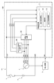
- FIG. 1 is a circuit diagram of a charging device AA according to an embodiment of the present invention.
- the charging device AA includes a generator 5, a battery 6 that is charged by the output power of the generator 5, a detection circuit 7 that detects an operating state of the generator 5, a fuse 8, and a power generation control device 100 as a regulator. .
- the generator 5 is a three-phase AC generator having three phases of AC1, AC2, and AC3, and one cycle of the generator 5 is N (where N is an integer satisfying N ⁇ 2). Composed. For example, when the generator 5 is driven by a four-cycle engine, one cycle of the generator 5 is configured with four states respectively corresponding to four strokes of intake, compression, ignition, and exhaust. .
- the input terminals IN1 to IN3 of the power generation control device 100 are connected to the phases AC1 to AC3, respectively.
- the detection circuit 7 detects the operation state of the generator 5 and outputs a sensor signal synchronized with the operation of the generator 5. Specifically, the detection circuit 7 generates a one-shot pulse each time it detects that the above-described state in the generator 5 has been switched, and outputs it as a sensor signal. For example, when the generator 5 is driven by a four-cycle engine, a one-shot pulse is generated each time the four strokes of intake, compression, ignition, and exhaust are switched.
- the output terminal OUT of the power generation control device 100 is connected to the positive electrode of the battery 6 via the fuse 8.
- the ground terminal GND of the power generation control device 100 connected to the reference potential source is connected to the negative electrode of the battery 6.
- the power generation control device 100 includes a control circuit 1, a zero cross signal generation circuit 20, and a drive circuit 30.
- the zero cross signal generation circuit 20 is connected to the input terminals IN1 to IN3 and the control circuit 1.
- the zero cross signal generation circuit 20 rectifies the voltage output from each of the phases AC1 to AC3 of the generator 5 and outputs the rectified voltage as each of the signals DC1 to DC3. Specifically, when the voltage output from the phase AC1 of the generator 5 is equal to or higher than a predetermined threshold voltage, the voltage of the signal DC1 is set to VH, and when the voltage is lower than the threshold voltage, the signal DC1 Is set to VL lower than VH, and the signal DC1 is output.
- the voltages of the signals DC2 and DC3 are set according to the result of comparison with the threshold voltage, similarly to the voltage output from the phase AC1 described above. Change the output.
- the drive circuit 30 is connected to the input terminals IN1 to IN3 and the control circuit 1, and includes switch elements Q1, Q2, and Q3 (not shown). Each of switch elements Q1 to Q3 is provided in a pair with each of phases AC1 to AC3 of generator 5.
- the drive circuit 30 turns on and off each of the switch elements Q1 to Q3 in accordance with a control signal output from the control circuit 1, and outputs output power from each of the phases AC1 to AC3 of the generator 5 to the output terminal OUT. And supply to the battery 6 via the fuse 8 is controlled.
- the relationship between the control of the switch elements Q1 to Q3 and the power supplied to the battery 6 will be described below with reference to FIGS.
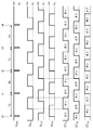
- FIG. 2 is a timing chart showing the operation of the switch elements Q1 to Q3.
- V SNS indicates the voltage of the sensor signal.
- V DC1 indicates a voltage obtained by rectifying the voltage of the signal DC1, that is, the voltage output from the phase AC1 of the generator 5.
- V DC2 indicates a voltage obtained by rectifying the voltage of the signal DC2, that is, the voltage output from the phase AC2 of the generator 5.
- V DC3 indicates a voltage obtained by rectifying the voltage of the signal DC3, that is, the voltage output from the phase AC3 of the generator 5.
- ST Q1 indicates the state of the switch element Q1
- ST Q2 indicates the state of the switch element Q2
- ST Q3 indicates the state of the switch element Q3.
- the voltage V SNS of the sensor signal is VL over a predetermined period. This indicates a one-shot pulse generated by the detection circuit 7 described above, and indicates that the state of the generator 5 is switched at each of these times t0 to t4.
- the switching element Q1 at the timing when the voltage V DC1 rises from VL to VH is turned on, the switching device Q1 at the timing when the voltage V DC1 falls from VH to VL in the OFF state.
- Each of the switch elements Q2 and Q3 is also turned on / off according to each of the voltages V DC2 and V DC3 , similarly to the switch element Q1.
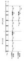
- FIG. 3 is a timing chart showing the operation of the switch element Q1.
- the battery 6 is connected depending on the relationship between the period in which the switching element Q1 is on and the period in which the voltage V DC1 is VH.
- the charging period changes, and the rate at which the output power from the phase AC1 of the generator 5 is supplied to the battery 6 changes. Therefore, by controlling the switch elements Q1 to Q3, the power supplied to the battery 6 can be controlled, and the charging of the battery 6 can be controlled.
- control circuit 1 is connected to the input terminal IN4, the output terminal OUT, the zero-cross signal generation circuit 20, and the drive circuit 30.
- the control circuit 1 includes a change rate acquisition unit 11, an estimation unit 12, and an output supply control unit 13, and performs PWM control of the switch elements Q1 to Q3.
- the rate-of-change acquisition unit 11 obtains the rate of change of the sensor cycle, as will be described later in detail in step S3 of FIG.
- the sensor cycle is a cycle in which a one-shot pulse is generated as a sensor signal, that is, a time from when the one-shot pulse is input to the control circuit 1 until it is input this time. , Tb, Tc, Td.
- the estimation unit 12 estimates the next sensor cycle by using the change rate of the sensor cycle obtained by the change rate acquisition unit 11, as will be described later in detail in step S3 of FIG.
- the output supply control unit 13 determines the operation amount ⁇ of the switch elements Q1 to Q3 in the next state using the next sensor cycle estimated by the estimation unit 12, as will be described later in detail in step S4 of FIG. Then, a control signal is output to the drive circuit 30, and the switch elements Q1 to Q3 are PWM-controlled.
- FIG. 4 is a flowchart of sensor interrupt processing performed by the control circuit 1. This sensor interruption process is executed each time the one-shot pulse generated by the detection circuit 7 as a sensor signal is input to the control circuit 1.
- step S1 the change rate acquisition unit 11 measures the sensor cycle, stores it as cycle data, and moves the process to step S2. According to this, the period in which each of the N states in the generator 5 continues is stored as the periodic data.
- step S2 the change rate acquisition unit 11 determines whether or not (N + 1) times or more of periodic data is stored. If it is determined that it is stored, the process proceeds to step S3, and if it is determined that it is not stored, the process proceeds to step S4.
- step S3 the change rate acquisition unit 11 and the estimation unit 12 estimate the period during which the next state continues, that is, the next sensor cycle T (n + 1) (where n is an arbitrary integer), and the process proceeds to step S4. Move processing.
- the process in step S3 will be described in detail below with reference to FIG.
- FIG. 5 exemplifies a case in which the period during which state 8 continues, that is, the sensor period in state 8 is estimated.
- State 8 is the next state, and state 7 is the current state.
- one cycle of the generator 5 is composed of four states, and the states 1 and 5 indicate the same state.
- Each of the states 2 to 4 and each of the states 6 to 8 shows the same state as in the states 1 and 5.
- the continuous period of state 4 is longer than the continuous period of state 3, the continuous period of state 8 which is the state after one cycle of state 4 is also one cycle after state 3 It becomes longer than the continuous period of the state 7 which is the state.
- the duration of the state 4 is shorter than the duration of the state 3
- the duration of the state 8 that is one cycle after the state 4 is also the state after one cycle of the state 3. It is shorter than the continuous period of a certain state 7.
- the rate of change of the continuous period of state 4 with respect to the period of continuous state 3 is substantially equal to the rate of change of the continuous period of state 8 with respect to the continuous period of state 7.
- the rate of change of the sensor cycle in state 4 with respect to the sensor cycle in state 3 is substantially equal to the rate of change of sensor cycle in state 8 with respect to the sensor cycle in state 7.
- the control circuit 1 first obtains the change rate of the sensor period in the state 4 with respect to the sensor period in the state 3 by the change rate acquisition unit 11.
- the rate of change of the sensor period in state 4 with respect to the sensor period in state 3 is 135%, and the sensor period in state 4 is 35% longer than the sensor period in state 3.
- the estimation unit 12 calculates the sensor cycle T8 in state 8 by the following equation (1). presume.
- T7 represents the sensor period in the state 7.
- RC T3-T4 indicates the rate of change of the sensor period in state 4 with respect to the sensor period in state 3.
- the sensor period T8 in the state 8 is estimated as “112.75”.
- step S4 the output supply control unit 13 determines the manipulated variable ⁇ of the switch elements Q1 to Q3 in the next state and outputs a control signal to the drive circuit 30.
- the sensor allocation shown in FIG. Finish the process. The process in step S4 will be described in detail below.
- step S4 when it is determined in step S2 that the change rate acquisition unit 11 has not stored (N + 1) or more period data will be described below.
- the control circuit 1 sets the operation amount ⁇ of the switch elements Q1 to Q3 in the next state to a predetermined value by the output supply control unit 13.
- step S4 when it is determined in step S2 that the change rate acquisition unit 11 has stored (N + 1) times or more of periodic data will be described below.
- control circuit 1 uses the output supply control unit 13 to first output the output voltage of the power generation control device 100 in the state before the state in which the next sensor cycle T (n + 1) is estimated in step S3, that is, the current state. Based on the target voltage, a difference ⁇ dif (n) between the output voltage and the target voltage is obtained by the following formula (2).
- Vout (n) indicates the output voltage of the power generation control device 100 in the current state.
- Vref represents a target voltage that is a target value of the output voltage Vout (n) of the power generation control device 100.
- Vout (n) is the output voltage of the power generation control device 100 in state 7
- ⁇ dif (n) is the power generation control device in state 7. The difference between the output voltage of 100 and the target voltage.
- control circuit 1 causes the output supply control unit 13 to calculate the output voltage and the target voltage based on the output voltage and the target voltage of the power generation control device 100 in the state immediately before the current state by the following formula (3). A difference ⁇ dif (n ⁇ 1) from the target voltage is obtained.
- Vout (n ⁇ 1) indicates the output voltage of the power generation control device 100 in the state immediately before the current state.
- Vref represents a target voltage that is a target value of the output voltage Vout (n ⁇ 1) of the power generation control device 100.
- Vout (n ⁇ 1) becomes the output voltage of the power generation control device 100 in state 6
- ⁇ dif (n ⁇ 1) becomes state 6 Is the difference between the output voltage of the power generation control device 100 and the target voltage.
- control circuit 1 determines the difference ⁇ dif (n) between the output voltage of the power generation control device 100 in the current state and the target voltage, and the difference between the output voltage of the power generation control device 100 in the previous state and the target voltage. Based on ⁇ dif (n ⁇ 1), the control amount ⁇ (n + 1) in the next state is obtained by the following equation (4).
- K0 and K1 indicate PI constants.
- ⁇ (n) indicates the control amount in the current state. For example, when the sensor period in state 8 in FIG. 5 is estimated in step S3, ⁇ (n) is the control amount in state 7.
- control circuit 1 calculates the next state by the following equation (5).
- the operation amount ⁇ of the switch elements Q1 to Q3 is determined.
- FIG. 6 is a diagram for explaining a case where the next sensor cycle is estimated by the control circuit 1 as described above.
- the process of step S3 in FIG. 4 causes the actual sensor period to be between the measured value T2d of the sensor period and the estimated value T2c ′ of the sensor period. No error occurs between the estimated sensor period.
- FIG. 7 is a diagram for explaining a case where the next sensor cycle is estimated as equal to the current sensor cycle, not the case where the control circuit 1 estimates the sensor cycle as described above.
- the sensor period is not constant, there is an error between the actual sensor period and the estimated sensor period, such as between the measured value T2d of the sensor period and the estimated value T2c ′ of the sensor period. Will occur.
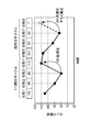
- FIG. 8 is a diagram showing a sensor cycle.
- the vertical axis represents the sensor period
- the horizontal axis represents the number of measurement of the sensor period.
- a solid line indicates a sensor cycle of the sensor signal output from the detection circuit 7, that is, an actual measurement value of the sensor cycle.
- the broken line indicates the sensor period estimated as described above by the control circuit 1 as described above with reference to FIG.
- the two-dot chain line indicates the sensor cycle when the next sensor cycle is equal to the current sensor cycle, as described above with reference to FIG.
- FIG. 9 is a diagram showing a charging current supplied to the battery 6 when the drive circuit 30 is controlled in accordance with the sensor cycle estimation result by the control circuit 1 described above with reference to FIG.
- FIG. 10 is a diagram showing the charging current supplied to the battery 6 when the drive circuit 30 is controlled on the assumption that the next sensor cycle described above with reference to FIG. 7 is equal to the current sensor cycle. 9 and 10, the vertical axis represents the charging current supplied to the battery 6, and the horizontal axis represents time.
- the control circuit 1 can supply a stable charging current to the battery 6 as compared with the case where the next sensor cycle is equal to the current sensor cycle. For this reason, the power generation control device 100 can efficiently supply power from the generator 5 to the battery 6.
- the battery 6 is applied as a load to which power is supplied from the generator 5, but the present invention is not limited to this.
- the generator 5 has three phases. However, the generator 5 is not limited to this, and may have, for example, one phase or four phases.
- control circuit 1 performs PWM control of the switch elements Q1 to Q3 provided in the drive circuit 30, but is not limited thereto, and may be, for example, phase controlled.
- the detection circuit 7 generates a one-shot pulse every time it detects that the above-described state in the generator 5 has been switched, but the present invention is not limited to this.
- a one-shot pulse may be generated each time a zero cross of each of the phases AC1 to AC3 of the generator 5 is detected.
- a one-shot pulse may be generated every time the rotation angle of the engine reaches a predetermined angle.
- the sensor cycle one cycle before is used as described above with reference to FIG. .
- a sensor cycle two cycles before or a sensor cycle three cycles before may be used, or a sensor cycle one cycle before and a sensor cycle two cycles before may be used in combination.
- control circuit 5 generator 6: battery 7: detection circuit 8: fuse 10: control circuit 11: change rate acquisition unit 12: estimation unit 13: output supply control unit 20: zero-cross signal generation circuit 30: drive circuit 100: Power generation control device Q1-Q3: Switch element AA: Charging device
Landscapes
- Engineering & Computer Science (AREA)
- Power Engineering (AREA)
- Control Of Eletrric Generators (AREA)
- Control Of Charge By Means Of Generators (AREA)
Description
(1) 本発明は、交流発電機(例えば、図1の発電機5に相当)から負荷(例えば、図1のバッテリ6に相当)に供給する電力を制御する制御回路(例えば、図1の制御回路1に相当)であって、現在の周期(例えば、図5の現在のサイクルに相当)より前の周期(例えば、図5の1つ前のサイクルに相当)における前記交流発電機の動作状況(例えば、図5のセンサ周期に相当)に基づいて、当該交流発電機の以後の動作状況(例えば、図5の状態8におけるセンサ周期に相当)を推定する推定手段(例えば、図1の推定部12に相当)と、前記推定手段による推定結果を用いて、前記負荷に対する前記交流発電機の出力の供給を制御する出力供給制御手段(例えば、図1の出力供給制御部13に相当)と、を備えることを特徴とする制御回路を提案している。




5:発電機
6:バッテリ
7:検出回路
8:ヒューズ
10:制御回路
11:変化率取得部
12:推定部
13:出力供給制御部
20:ゼロクロス信号生成回路
30:駆動回路
100:発電制御装置
Q1~Q3:スイッチ素子
AA:充電装置
Claims (4)
- 交流発電機から負荷に供給する電力を制御する制御回路であって、
現在の周期より前の周期における前記交流発電機の動作状況に基づいて、当該交流発電機の以後の動作状況を推定する推定手段と、
前記推定手段による推定結果を用いて、前記負荷に対する前記交流発電機の出力の供給を制御する出力供給制御手段と、を備えることを特徴とする制御回路。 - 前記交流発電機の状態が第2の状態から第1の状態に遷移すると、当該第2の状態である期間に対する当該第1の状態である期間の変化率を求める変化率取得手段を備え、
前記推定手段は、前記交流発電機の状態が第2の状態から第1の状態に遷移する際に、当該第2の状態であった期間と、1周期前の前記交流発電機において前記変化率取得手段により求められた変化率と、に基づいて、第1の状態である期間を推定することを特徴とする請求項1に記載の制御回路。 - 前記出力供給制御手段は、前記推定手段により推定された期間と、前記第2の状態の前の状態である第3の状態における前記負荷への供給電圧および目標電圧と、当該第2の状態における前記負荷への供給電圧および目標電圧と、を用いて、前記負荷に対する前記交流発電機の出力の供給を制御することを特徴とする請求項2に記載の制御回路。
- 請求項1から3のいずれかに記載の制御回路を有し、前記交流発電機から出力された電力を前記負荷に供給することを特徴とする発電装置。
Priority Applications (4)
| Application Number | Priority Date | Filing Date | Title |
|---|---|---|---|
| GB1411505.9A GB2512237B (en) | 2012-03-19 | 2012-12-25 | Control circuit, and power generation device having the same |
| JP2013537709A JP5405697B1 (ja) | 2012-03-19 | 2012-12-25 | 制御回路、および制御回路を備える発電装置 |
| US14/365,665 US9401618B2 (en) | 2012-03-19 | 2012-12-25 | Control circuit, and power generation device having the same |
| DE201211005056 DE112012005056T5 (de) | 2012-03-19 | 2012-12-25 | Steuer-/Regelschaltung sowie eine solche aufweisende Stromerzeugungsvorrichtung |
Applications Claiming Priority (2)
| Application Number | Priority Date | Filing Date | Title |
|---|---|---|---|
| JP2012061532 | 2012-03-19 | ||
| JP2012-061532 | 2012-03-19 |
Publications (1)
| Publication Number | Publication Date |
|---|---|
| WO2013140694A1 true WO2013140694A1 (ja) | 2013-09-26 |
Family
ID=49222180
Family Applications (1)
| Application Number | Title | Priority Date | Filing Date |
|---|---|---|---|
| PCT/JP2012/083505 Ceased WO2013140694A1 (ja) | 2012-03-19 | 2012-12-25 | 制御回路、および制御回路を備える発電装置 |
Country Status (6)
| Country | Link |
|---|---|
| US (1) | US9401618B2 (ja) |
| JP (1) | JP5405697B1 (ja) |
| DE (1) | DE112012005056T5 (ja) |
| GB (1) | GB2512237B (ja) |
| IT (1) | ITTO20130175A1 (ja) |
| WO (1) | WO2013140694A1 (ja) |
Families Citing this family (3)
| Publication number | Priority date | Publication date | Assignee | Title |
|---|---|---|---|---|
| JP6322979B2 (ja) * | 2012-12-28 | 2018-05-16 | 株式会社リコー | 充電装置及び充電システム |
| KR101697099B1 (ko) * | 2016-03-23 | 2017-02-02 | 전자부품연구원 | 최대출력 추종을 위한 최적 댐핑 제어 방법 및 이를 지원하는 파력 발전 시스템 |
| KR102485380B1 (ko) | 2017-11-30 | 2023-01-05 | 현대자동차주식회사 | 차량용 알터네이터 제어 장치 및 그 방법 |
Citations (3)
| Publication number | Priority date | Publication date | Assignee | Title |
|---|---|---|---|---|
| JPH0556698A (ja) * | 1991-08-26 | 1993-03-05 | Toshiba Corp | 電力需要予測制御装置 |
| JP2010252551A (ja) * | 2009-04-16 | 2010-11-04 | Denso Corp | 発電制御装置 |
| JP2012039698A (ja) * | 2010-08-04 | 2012-02-23 | Shindengen Electric Mfg Co Ltd | 位相制御装置、バッテリ充電装置、および位相制御方法 |
Family Cites Families (5)
| Publication number | Priority date | Publication date | Assignee | Title |
|---|---|---|---|---|
| US2266607A (en) * | 1941-04-30 | 1941-12-16 | Gen Electric | Regulating system |
| US2648783A (en) * | 1946-12-19 | 1953-08-11 | Master Vibrator Co | Electrical control system for engine driven generator sets |
| JP4479919B2 (ja) * | 2006-03-29 | 2010-06-09 | 株式会社デンソー | 電気自動車の制御装置 |
| JP5283259B2 (ja) | 2008-09-19 | 2013-09-04 | 本田技研工業株式会社 | 発電制御装置 |
| JP2015055155A (ja) * | 2013-09-10 | 2015-03-23 | スズキ株式会社 | 減速時発電制御装置 |
-
2012
- 2012-12-25 US US14/365,665 patent/US9401618B2/en active Active
- 2012-12-25 GB GB1411505.9A patent/GB2512237B/en active Active
- 2012-12-25 JP JP2013537709A patent/JP5405697B1/ja active Active
- 2012-12-25 DE DE201211005056 patent/DE112012005056T5/de not_active Withdrawn
- 2012-12-25 WO PCT/JP2012/083505 patent/WO2013140694A1/ja not_active Ceased
-
2013
- 2013-03-05 IT ITTO20130175 patent/ITTO20130175A1/it unknown
Patent Citations (3)
| Publication number | Priority date | Publication date | Assignee | Title |
|---|---|---|---|---|
| JPH0556698A (ja) * | 1991-08-26 | 1993-03-05 | Toshiba Corp | 電力需要予測制御装置 |
| JP2010252551A (ja) * | 2009-04-16 | 2010-11-04 | Denso Corp | 発電制御装置 |
| JP2012039698A (ja) * | 2010-08-04 | 2012-02-23 | Shindengen Electric Mfg Co Ltd | 位相制御装置、バッテリ充電装置、および位相制御方法 |
Also Published As
| Publication number | Publication date |
|---|---|
| DE112012005056T5 (de) | 2014-10-02 |
| ITTO20130175A1 (it) | 2013-09-20 |
| GB201411505D0 (en) | 2014-08-13 |
| GB2512237B (en) | 2017-01-18 |
| GB2512237A (en) | 2014-09-24 |
| JP5405697B1 (ja) | 2014-02-05 |
| US20140306682A1 (en) | 2014-10-16 |
| JPWO2013140694A1 (ja) | 2015-08-03 |
| US9401618B2 (en) | 2016-07-26 |
Similar Documents
| Publication | Publication Date | Title |
|---|---|---|
| JP6373434B1 (ja) | 交流回転電機の制御装置 | |
| US9431951B2 (en) | Direct torque control motor controller with transient current limiter | |
| JP5272319B2 (ja) | 電力変換装置 | |
| JPWO2007114272A1 (ja) | バッテリ充電装置、3相電圧生成回路、3相電圧生成方法、および遅角制御方法 | |
| US9444384B2 (en) | Direct torque control motor controller with transient current limiter | |
| US9407189B2 (en) | Direct torque control motor controller with torque ripple reduction | |
| JP6007511B2 (ja) | 電力変換装置 | |
| WO2010055556A1 (ja) | 電力変換装置のコンデンサ容量推定装置およびコンデンサ容量推定方法 | |
| US9285410B2 (en) | Control circuit, and power generation device having the same | |
| JP5405697B1 (ja) | 制御回路、および制御回路を備える発電装置 | |
| WO2014033864A1 (ja) | 電源装置及び電源装置の制御方法 | |
| JP2008067591A (ja) | インバータ装置及びインバータ装置のオンデューティ設定手段の設計方法 | |
| JP2016086510A (ja) | 電力変換装置 | |
| CN104995842B (zh) | Pwm输出与ad变换的竞争避免控制装置及竞争避免控制方法、以及功率控制系统 | |
| JP5652454B2 (ja) | 電力変換装置 | |
| JP2018074743A (ja) | Dc/dcコンバータの制御装置 | |
| JP6663342B2 (ja) | 制御装置 | |
| JP2019041449A (ja) | Dc/dcコンバータの制御装置 | |
| JP6295183B2 (ja) | モータ制御装置 | |
| TWI542132B (zh) | 預測性非連續充電模式控制方法及功率轉換器 | |
| JP6383884B1 (ja) | 発電制御装置、発電制御方法および発電装置 | |
| JP2018137839A (ja) | 力率改善回路 | |
| JP6455406B2 (ja) | 電力変換装置 | |
| JP5518378B2 (ja) | 電力供給装置 | |
| JP6397734B2 (ja) | 直流電動機の制御装置 |
Legal Events
| Date | Code | Title | Description |
|---|---|---|---|
| ENP | Entry into the national phase |
Ref document number: 2013537709 Country of ref document: JP Kind code of ref document: A |
|
| 121 | Ep: the epo has been informed by wipo that ep was designated in this application |
Ref document number: 12871963 Country of ref document: EP Kind code of ref document: A1 |
|
| WWE | Wipo information: entry into national phase |
Ref document number: 14365665 Country of ref document: US |
|
| ENP | Entry into the national phase |
Ref document number: 1411505 Country of ref document: GB Kind code of ref document: A Free format text: PCT FILING DATE = 20121225 |
|
| WWE | Wipo information: entry into national phase |
Ref document number: 1411505.9 Country of ref document: GB |
|
| WWE | Wipo information: entry into national phase |
Ref document number: 1120120050568 Country of ref document: DE Ref document number: 112012005056 Country of ref document: DE |
|
| 122 | Ep: pct application non-entry in european phase |
Ref document number: 12871963 Country of ref document: EP Kind code of ref document: A1 |