WO2013140696A1 - Dispositif de commande pour transmission automatique de véhicule hybride - Google Patents
Dispositif de commande pour transmission automatique de véhicule hybride Download PDFInfo
- Publication number
- WO2013140696A1 WO2013140696A1 PCT/JP2012/083687 JP2012083687W WO2013140696A1 WO 2013140696 A1 WO2013140696 A1 WO 2013140696A1 JP 2012083687 W JP2012083687 W JP 2012083687W WO 2013140696 A1 WO2013140696 A1 WO 2013140696A1
- Authority
- WO
- WIPO (PCT)
- Prior art keywords
- drag
- oil pump
- automatic transmission
- oil
- hybrid vehicle
- Prior art date
- Legal status (The legal status is an assumption and is not a legal conclusion. Google has not performed a legal analysis and makes no representation as to the accuracy of the status listed.)
- Ceased
Links
Images


Classifications
-
- F—MECHANICAL ENGINEERING; LIGHTING; HEATING; WEAPONS; BLASTING
- F16—ENGINEERING ELEMENTS AND UNITS; GENERAL MEASURES FOR PRODUCING AND MAINTAINING EFFECTIVE FUNCTIONING OF MACHINES OR INSTALLATIONS; THERMAL INSULATION IN GENERAL
- F16H—GEARING
- F16H61/00—Control functions within control units of change-speed- or reversing-gearings for conveying rotary motion ; Control of exclusively fluid gearing, friction gearing, gearings with endless flexible members or other particular types of gearing
- F16H61/0021—Generation or control of line pressure
- F16H61/0025—Supply of control fluid; Pumps therefor
- F16H61/0031—Supply of control fluid; Pumps therefor using auxiliary pumps, e.g. pump driven by a different power source than the engine
-
- B—PERFORMING OPERATIONS; TRANSPORTING
- B60—VEHICLES IN GENERAL
- B60W—CONJOINT CONTROL OF VEHICLE SUB-UNITS OF DIFFERENT TYPE OR DIFFERENT FUNCTION; CONTROL SYSTEMS SPECIALLY ADAPTED FOR HYBRID VEHICLES; ROAD VEHICLE DRIVE CONTROL SYSTEMS FOR PURPOSES NOT RELATED TO THE CONTROL OF A PARTICULAR SUB-UNIT
- B60W10/00—Conjoint control of vehicle sub-units of different type or different function
- B60W10/30—Conjoint control of vehicle sub-units of different type or different function including control of auxiliary equipment, e.g. air-conditioning compressors or oil pumps
-
- B—PERFORMING OPERATIONS; TRANSPORTING
- B60—VEHICLES IN GENERAL
- B60K—ARRANGEMENT OR MOUNTING OF PROPULSION UNITS OR OF TRANSMISSIONS IN VEHICLES; ARRANGEMENT OR MOUNTING OF PLURAL DIVERSE PRIME-MOVERS IN VEHICLES; AUXILIARY DRIVES FOR VEHICLES; INSTRUMENTATION OR DASHBOARDS FOR VEHICLES; ARRANGEMENTS IN CONNECTION WITH COOLING, AIR INTAKE, GAS EXHAUST OR FUEL SUPPLY OF PROPULSION UNITS IN VEHICLES
- B60K6/00—Arrangement or mounting of plural diverse prime-movers for mutual or common propulsion, e.g. hybrid propulsion systems comprising electric motors and internal combustion engines
- B60K6/20—Arrangement or mounting of plural diverse prime-movers for mutual or common propulsion, e.g. hybrid propulsion systems comprising electric motors and internal combustion engines the prime-movers consisting of electric motors and internal combustion engines, e.g. HEVs
- B60K6/50—Architecture of the driveline characterised by arrangement or kind of transmission units
- B60K6/52—Driving a plurality of drive axles, e.g. four-wheel drive
-
- B—PERFORMING OPERATIONS; TRANSPORTING
- B60—VEHICLES IN GENERAL
- B60K—ARRANGEMENT OR MOUNTING OF PROPULSION UNITS OR OF TRANSMISSIONS IN VEHICLES; ARRANGEMENT OR MOUNTING OF PLURAL DIVERSE PRIME-MOVERS IN VEHICLES; AUXILIARY DRIVES FOR VEHICLES; INSTRUMENTATION OR DASHBOARDS FOR VEHICLES; ARRANGEMENTS IN CONNECTION WITH COOLING, AIR INTAKE, GAS EXHAUST OR FUEL SUPPLY OF PROPULSION UNITS IN VEHICLES
- B60K6/00—Arrangement or mounting of plural diverse prime-movers for mutual or common propulsion, e.g. hybrid propulsion systems comprising electric motors and internal combustion engines
- B60K6/20—Arrangement or mounting of plural diverse prime-movers for mutual or common propulsion, e.g. hybrid propulsion systems comprising electric motors and internal combustion engines the prime-movers consisting of electric motors and internal combustion engines, e.g. HEVs
- B60K6/42—Arrangement or mounting of plural diverse prime-movers for mutual or common propulsion, e.g. hybrid propulsion systems comprising electric motors and internal combustion engines the prime-movers consisting of electric motors and internal combustion engines, e.g. HEVs characterised by the architecture of the hybrid electric vehicle
- B60K6/44—Series-parallel type
-
- B—PERFORMING OPERATIONS; TRANSPORTING
- B60—VEHICLES IN GENERAL
- B60K—ARRANGEMENT OR MOUNTING OF PROPULSION UNITS OR OF TRANSMISSIONS IN VEHICLES; ARRANGEMENT OR MOUNTING OF PLURAL DIVERSE PRIME-MOVERS IN VEHICLES; AUXILIARY DRIVES FOR VEHICLES; INSTRUMENTATION OR DASHBOARDS FOR VEHICLES; ARRANGEMENTS IN CONNECTION WITH COOLING, AIR INTAKE, GAS EXHAUST OR FUEL SUPPLY OF PROPULSION UNITS IN VEHICLES
- B60K6/00—Arrangement or mounting of plural diverse prime-movers for mutual or common propulsion, e.g. hybrid propulsion systems comprising electric motors and internal combustion engines
- B60K6/20—Arrangement or mounting of plural diverse prime-movers for mutual or common propulsion, e.g. hybrid propulsion systems comprising electric motors and internal combustion engines the prime-movers consisting of electric motors and internal combustion engines, e.g. HEVs
- B60K6/50—Architecture of the driveline characterised by arrangement or kind of transmission units
- B60K6/54—Transmission for changing ratio
- B60K6/547—Transmission for changing ratio the transmission being a stepped gearing
-
- B—PERFORMING OPERATIONS; TRANSPORTING
- B60—VEHICLES IN GENERAL
- B60W—CONJOINT CONTROL OF VEHICLE SUB-UNITS OF DIFFERENT TYPE OR DIFFERENT FUNCTION; CONTROL SYSTEMS SPECIALLY ADAPTED FOR HYBRID VEHICLES; ROAD VEHICLE DRIVE CONTROL SYSTEMS FOR PURPOSES NOT RELATED TO THE CONTROL OF A PARTICULAR SUB-UNIT
- B60W10/00—Conjoint control of vehicle sub-units of different type or different function
- B60W10/04—Conjoint control of vehicle sub-units of different type or different function including control of propulsion units
- B60W10/08—Conjoint control of vehicle sub-units of different type or different function including control of propulsion units including control of electric propulsion units, e.g. motors or generators
-
- B—PERFORMING OPERATIONS; TRANSPORTING
- B60—VEHICLES IN GENERAL
- B60W—CONJOINT CONTROL OF VEHICLE SUB-UNITS OF DIFFERENT TYPE OR DIFFERENT FUNCTION; CONTROL SYSTEMS SPECIALLY ADAPTED FOR HYBRID VEHICLES; ROAD VEHICLE DRIVE CONTROL SYSTEMS FOR PURPOSES NOT RELATED TO THE CONTROL OF A PARTICULAR SUB-UNIT
- B60W10/00—Conjoint control of vehicle sub-units of different type or different function
- B60W10/10—Conjoint control of vehicle sub-units of different type or different function including control of change-speed gearings
- B60W10/11—Stepped gearings
- B60W10/115—Stepped gearings with planetary gears
-
- B—PERFORMING OPERATIONS; TRANSPORTING
- B60—VEHICLES IN GENERAL
- B60W—CONJOINT CONTROL OF VEHICLE SUB-UNITS OF DIFFERENT TYPE OR DIFFERENT FUNCTION; CONTROL SYSTEMS SPECIALLY ADAPTED FOR HYBRID VEHICLES; ROAD VEHICLE DRIVE CONTROL SYSTEMS FOR PURPOSES NOT RELATED TO THE CONTROL OF A PARTICULAR SUB-UNIT
- B60W20/00—Control systems specially adapted for hybrid vehicles
- B60W20/30—Control strategies involving selection of transmission gear ratio
-
- B—PERFORMING OPERATIONS; TRANSPORTING
- B60—VEHICLES IN GENERAL
- B60W—CONJOINT CONTROL OF VEHICLE SUB-UNITS OF DIFFERENT TYPE OR DIFFERENT FUNCTION; CONTROL SYSTEMS SPECIALLY ADAPTED FOR HYBRID VEHICLES; ROAD VEHICLE DRIVE CONTROL SYSTEMS FOR PURPOSES NOT RELATED TO THE CONTROL OF A PARTICULAR SUB-UNIT
- B60W20/00—Control systems specially adapted for hybrid vehicles
-
- B—PERFORMING OPERATIONS; TRANSPORTING
- B60—VEHICLES IN GENERAL
- B60Y—INDEXING SCHEME RELATING TO ASPECTS CROSS-CUTTING VEHICLE TECHNOLOGY
- B60Y2300/00—Purposes or special features of road vehicle drive control systems
- B60Y2300/60—Control of electric machines, e.g. problems related to electric motors or generators
- B60Y2300/64—Drag run or drag torque compensation, e.g. motor to drive engine with drag torque or engine speed is brought to start speed before injection and firing
-
- F—MECHANICAL ENGINEERING; LIGHTING; HEATING; WEAPONS; BLASTING
- F02—COMBUSTION ENGINES; HOT-GAS OR COMBUSTION-PRODUCT ENGINE PLANTS
- F02D—CONTROLLING COMBUSTION ENGINES
- F02D29/00—Controlling engines, such controlling being peculiar to the devices driven thereby, the devices being other than parts or accessories essential to engine operation, e.g. controlling of engines by signals external thereto
- F02D29/02—Controlling engines, such controlling being peculiar to the devices driven thereby, the devices being other than parts or accessories essential to engine operation, e.g. controlling of engines by signals external thereto peculiar to engines driving vehicles; peculiar to engines driving variable pitch propellers
-
- Y—GENERAL TAGGING OF NEW TECHNOLOGICAL DEVELOPMENTS; GENERAL TAGGING OF CROSS-SECTIONAL TECHNOLOGIES SPANNING OVER SEVERAL SECTIONS OF THE IPC; TECHNICAL SUBJECTS COVERED BY FORMER USPC CROSS-REFERENCE ART COLLECTIONS [XRACs] AND DIGESTS
- Y02—TECHNOLOGIES OR APPLICATIONS FOR MITIGATION OR ADAPTATION AGAINST CLIMATE CHANGE
- Y02T—CLIMATE CHANGE MITIGATION TECHNOLOGIES RELATED TO TRANSPORTATION
- Y02T10/00—Road transport of goods or passengers
- Y02T10/60—Other road transportation technologies with climate change mitigation effect
- Y02T10/62—Hybrid vehicles
-
- Y—GENERAL TAGGING OF NEW TECHNOLOGICAL DEVELOPMENTS; GENERAL TAGGING OF CROSS-SECTIONAL TECHNOLOGIES SPANNING OVER SEVERAL SECTIONS OF THE IPC; TECHNICAL SUBJECTS COVERED BY FORMER USPC CROSS-REFERENCE ART COLLECTIONS [XRACs] AND DIGESTS
- Y10—TECHNICAL SUBJECTS COVERED BY FORMER USPC
- Y10S—TECHNICAL SUBJECTS COVERED BY FORMER USPC CROSS-REFERENCE ART COLLECTIONS [XRACs] AND DIGESTS
- Y10S903/00—Hybrid electric vehicles, HEVS
- Y10S903/902—Prime movers comprising electrical and internal combustion motors
Definitions
- the present invention relates to a control device for an automatic transmission mounted on, for example, a hybrid vehicle, and more specifically, a hybrid that controls a neutral state during EV traveling and supplies lubricating oil to a friction engagement element with an electric oil pump.
- the present invention relates to a control device for an automatic transmission for a vehicle.
- An object of the present invention is to provide a control device for an automatic transmission for a hybrid vehicle.
- the present invention is a machine driven by an internal combustion engine (2) in a power transmission path (L) between the internal combustion engine (2) and drive wheels (80fl, 80fr).
- the friction engagement elements (C-1, C-2, C-3, B-1, B-2) are controlled to be released, and the automatic transmission (10) is set to the neutral state.
- the amount of oil supplied to the cancel oil chamber (115) of the friction engagement element (for example, C-1) by the electric oil pump (32) during the EV traveling from the state where the hybrid vehicle is stopped is as follows.
- a cancellation control means (52) for commanding start of the internal combustion engine (2) to rotationally drive the mechanical oil pump (31) when the drag determination means (51) determines that the condition for generating the drag is satisfied.
- the drag determining means satisfies the condition that the friction engagement element is dragged when the amount of oil supplied to the cancel oil chamber of the friction engagement element by the electric oil pump is insufficient during EV traveling.
- the drag elimination control means commands the start of the internal combustion engine and rotationally drives the mechanical oil pump. Therefore, when drag is generated in the friction engagement element (when generation is predicted) ), A large amount of oil from the mechanical oil pump can be supplied to the canceling oil chamber of the friction engagement element, and drag generation in the friction engagement element can be prevented. Since the occurrence of drag can be prevented in this way, the electric oil pump can be reduced in size compared with the case where the occurrence of drag is prevented with a large electric oil pump, which improves vehicle mounting and reduces costs. Can be planned.
- the condition for causing the drag is set so as to be more easily established as the elapsed time (t) is shorter and the vehicle speed (V) is higher.
- the condition that causes dragging is set so that the longer the elapsed time from the start of EV travel and the higher the vehicle speed, the more easily it is established.
- the occurrence (prediction) of dragging of the friction engagement element can be accurately determined according to the amount of oil supplied to the cancel oil chamber. Accordingly, unnecessary starting of the internal combustion engine can be prevented, but when drag is generated in the friction engagement element (when generation is predicted), drag generation in the friction engagement element is appropriately performed. Can be prevented.
- the present invention includes an oil temperature detecting means (43) for detecting the oil temperature (T), The condition for causing the dragging is set such that the lower the oil temperature (T), the easier it is established.
- the conditions under which drag is generated are set such that the lower the oil temperature, the easier it is established. Therefore, the amount of oil supplied to the canceling oil chamber of the friction engagement element by the electric oil pump that changes depending on the oil temperature. Accordingly, it is possible to accurately determine the occurrence (prediction) of dragging of the friction engagement element. Accordingly, unnecessary starting of the internal combustion engine can be prevented, but when drag is generated in the friction engagement element (when generation is predicted), drag generation in the friction engagement element is appropriately performed. Can be prevented.
- the drag generation condition is set so as to include, as a safety margin (M), a time required to reach the idle speed after the internal combustion engine (2) is started. It is characterized by that.
- M safety margin
- the condition for causing the drag is set so as to include, as a safety margin, the time to reach the idle speed after the internal combustion engine is started.
- the start of the engine can be completed, and the occurrence of dragging at the frictional engagement element can be reliably prevented.
- an abnormality determining means (45a) for determining that an abnormality has occurred in the electric oil pump (32),
- a timing stop means (41a) for stopping the elapsed time measurement by the elapsed time measurement means (41) while the abnormality determination means (45a) determines that the abnormality of the electric oil pump (32) has occurred. It is characterized by having.
- the condition for causing drag on the friction engagement element can be established taking into account the occurrence time of the abnormality of the electric oil pump, and even if an abnormality occurs in the electric oil pump, the friction engagement Generation of drag in the element can be reliably prevented.
- the abnormality determining means (45a) determines the occurrence of abnormality of the electric oil pump (32) at predetermined time intervals, The abnormality determination means (45a) counts the number of occurrences of the abnormality (N), and when the predetermined number ( ⁇ ) is exceeded, it is determined that a failure has occurred in the electric oil pump (32). And a failure determination means (45b) for instructing start of the internal combustion engine (2) to rotationally drive the mechanical oil pump (31).
- the mechanical oil pump is rotationally driven by instructing the start of the internal combustion engine.
- the mechanical oil pump breaks down, the mechanical oil pump is reliably driven, and the occurrence of drag in the friction engagement element can be reliably prevented.
- the driving state of the internal combustion engine (2) is changed after a predetermined time from the start of the start of the internal combustion engine (2) by the drag elimination control means (52). It is characterized by having cancellation termination control means (53) for canceling.
- the cancellation end control means releases the driving state of the internal combustion engine after a predetermined time since the drag cancellation control means commands the start of the internal combustion engine, so that the cancel oil chamber of the friction engagement element is filled with oil. It is possible to prevent the internal combustion engine from being driven wastefully later.
- 1 is a schematic cross-sectional view showing an automatic transmission for a hybrid vehicle.
- the block diagram which shows the control apparatus of the automatic transmission for hybrid vehicles.
- the flowchart which shows drag cancellation control.
- a hybrid vehicle 100 is a rear motor type hybrid vehicle, and is equipped with an internal combustion engine (E / G) 2 on the front side, and the internal combustion engine 2 and the left and right wheels on the front side.
- E / G internal combustion engine
- a so-called FF (front engine, front drive) type vehicle in which a hybrid vehicle automatic transmission (hereinafter simply referred to as "automatic transmission") 10 is mounted on a transmission path between (drive wheels) 80fl and 80fr.
- a rear motor (rotating electric machine) 20 that is drivingly connected to the left and right wheels (drive wheels) 80 rl and 80 rr on the rear side. Rear wheel drive is possible during traveling, and four-wheel drive is possible during hybrid traveling.
- a belt-type integrated starter generator 3A is connected to the internal combustion engine 2, and the internal combustion engine 2 is configured to be startable.
- the belt-type integrated starter / generator (BISG) 3A can start the internal combustion engine 2 at a high output by being supplied with electric power from a high voltage battery (Hi-V Battery) 24 via an inverter 23. At the same time, the high-voltage battery 24 can be charged while the internal combustion engine 2 is being started (driven).
- One starter (Starter) 3B is a starter that is driven by a general low-voltage battery (Lo-V Battery) 26 (so-called 12V type power supply).
- Lo-V Battery general low-voltage battery
- 12V type power supply a general low-voltage battery
- this hybrid vehicle 100 after the rotational speed of the internal combustion engine 2 is increased to a rotational speed higher than the idle rotational speed using a belt-type integrated starter generator (BISG) 3 ⁇ / b> A at room temperature (for example, 0 degrees or more), the internal combustion engine 2 is ignited, and at a low temperature (for example, less than 0 degrees), the internal combustion engine 2 is normally started using the starter 3B.
- BISG belt-type integrated starter generator
- the internal combustion engine 2 is connected to an automatic transmission 10 described later in detail.
- the automatic transmission 10 roughly includes a torque converter (T / C) 4, an automatic transmission mechanism (T / M) 5, a hydraulic control device (V / B) 6, and the like.
- a torque converter 4 is connected to the drive.
- An automatic transmission mechanism (T / M) 5 is drivingly connected to the torque converter 4, and the automatic transmission mechanism 5 is connected to the left and right axles 81l through a differential device D (see FIG. 2) as will be described in detail later.
- 81r is connected to the front left and right wheels 80fl and 80fr.
- the automatic transmission mechanism 5 is provided with a hydraulic control device (V / B) 6 for hydraulically controlling a friction engagement element (clutch or brake) described later.
- V / B hydraulic control device
- a built-in solenoid valve or the like is electronically controlled based on an electronic command from a transmission control unit (TCU: Transmission Control Unit) 1.
- TCU Transmission Control Unit
- the hydraulic control device 6 is provided with an electric oil pump 32 that is driven independently of the internal combustion engine 2, and the electric oil pump 32 is connected to the hydraulic control device 6. It is configured to be able to supply hydraulic pressure.
- the electric oil pump 32 and the control unit 1 are driven using the electric power of the low voltage battery 26.
- the low voltage battery 26 is connected to a high voltage battery 24 via a DC / DC converter (step-down circuit) 25 and is configured to be supplied with electric power from the high voltage battery 24.
- the rear motor 20 is connected to a high voltage battery 24 via an inverter 23, and is configured to be capable of power running and regeneration.
- the rear motor 20 is drivingly connected to a gear box (Gear Box) 21 through a motor disconnecting clutch CM.
- the gear box 21 incorporates a reduction gear mechanism and a differential device with a predetermined reduction ratio (not shown).
- the motor disconnecting clutch CM When the motor disconnecting clutch CM is engaged, the rotation of the rear motor 20 is reduced to the reduction gear of the gear box 21. While decelerating by the mechanism and absorbing the differential rotation of the left and right axles 82l and 82r by the differential device, it is transmitted to the left and right wheels 80rl and 80rr on the rear side.
- the automatic transmission 10 is disposed on a power transmission path L between the internal combustion engine 2 (see FIG. 1) and the left and right wheels 80fl and 80fr on the front side, and is automatically connected to the crankshaft of the internal combustion engine 2.
- a transmission input shaft 8 is provided, and the torque converter 4 and the automatic transmission mechanism 5 described above are provided around the axial direction of the input shaft 8.
- the torque converter 4 includes a pump impeller 4a connected to the input shaft 8 of the automatic transmission 10, a turbine runner 4b to which rotation of the pump impeller 4a is transmitted via a working fluid, and the turbine runner 4b to the pump impeller 4a.
- the turbine runner 4b is connected to the input shaft 12 of the automatic transmission mechanism 5 disposed coaxially with the input shaft 8. It is connected.
- the torque converter 4 is provided with a lock-up clutch 7, and when the lock-up clutch 7 is engaged, the rotation of the input shaft 8 of the automatic transmission 10 causes the input shaft of the automatic transmission mechanism 5 to rotate. 12 is transmitted directly.
- the stator 4c is fixed by the one-way clutch F in a state where the rotation of the turbine runner 4b is lower than the rotation of the pump impeller 4a, receives the reaction force of the oil flow, and generates a torque increasing action.
- the rotation of the runner 4b is exceeded, the engine runs idle and the oil flow does not act in the negative direction.
- the pump impeller 4a has a drive shaft 4d on the automatic transmission mechanism 5 side connected to a drive gear 31a of a mechanical oil pump 31 disposed in a partition wall 9a fixed to the transmission case 9.
- the drive gear 31a forms an expansion / contraction space between the driven gear 31b and the driven gear 31b.
- the drive gear 31a sucks oil from a suction port (not shown) during driving rotation and compresses and discharges the oil to a discharge port (not shown). That is, the mechanical oil pump 31 is drivingly connected to the internal combustion engine 2 via the input shaft 8.
- the mechanical oil pump 31 operates the friction engagement elements (clutches C-1, C-2, C-3, B-1, B-2) described later while traveling with the driving force of the internal combustion engine 2. Oil to be supplied to the hydraulic control device 6.
- the automatic transmission mechanism 5 includes a planetary gear SP and a planetary gear unit PU on the input shaft 12.
- the planetary gear SP is a so-called single pinion planetary gear that includes a sun gear S1, a carrier CR1, and a ring gear R1, and has a pinion P1 that meshes with the sun gear S1 and the ring gear R1.
- the planetary gear unit PU has a sun gear S2, a sun gear S3, a carrier CR2, and a ring gear R2 as four rotating elements.
- the carrier CR2 has a long pinion PL that meshes with the sun gear S2 and the ring gear R2, and the sun gear S3.
- This is a so-called Ravigneaux type planetary gear that has meshing short pinions PS that mesh with each other.
- the sun gear S1 of the planetary gear SP is connected to the boss portion of the partition wall 9a fixed integrally with the transmission case 9, and the rotation is fixed.
- the ring gear R1 is rotated in the same rotation as the input shaft 12 (hereinafter referred to as “input rotation”).
- the carrier CR1 is decelerated by reducing the input rotation by the fixed sun gear S1 and the input rotating ring gear R1, and also includes the clutch (friction engagement element) C-1 and the clutch (friction engagement). Element) connected to C-3.
- the sun gear S2 of the planetary gear unit PU is connected to a brake (friction engagement element) B-1 formed of a band brake and can be fixed to the transmission case 9, and is connected to the clutch C-3.
- the carrier CR1 can be decelerated and rotated via the clutch C-3.
- the sun gear S3 is connected to the clutch C-1, so that the decelerated rotation of the carrier CR1 can be input.
- the carrier CR2 is connected to a clutch (friction engagement element) C-2 to which the rotation of the input shaft 12 is input, and the input rotation can be freely input via the clutch C-2.
- a clutch (friction engagement element) C-2 Connected to the one-way clutch F-1 and the brake (friction engagement element) B-2, rotation in one direction with respect to the transmission case is restricted via the one-way clutch F-1, and the brake B-2
- the rotation can be freely fixed via the.
- the ring gear R2 is connected to a counter gear 11.
- the counter gear 11 is connected to wheels 80fl and 80fr via a counter shaft 15 and a differential device D.
- the clutch C-1 includes a friction plate 111 and a hydraulic servo 110 that engages and releases the friction plate 111.
- the hydraulic servo 110 includes a clutch drum 112 having a cylinder portion formed therein, a piston 113 disposed so as to face the cylinder portion of the clutch drum 112 and movably in the axial direction with respect to the clutch drum 112, It has a return plate 117 disposed so as not to move in the axial direction with respect to the clutch drum 112 by a snap ring 119, and a return spring 116 contracted between the piston 113 and the return plate 117.
- a hydraulic oil chamber 114 is formed between the cylinder portion of the clutch drum 112 and the piston 113, and a cancel oil chamber 115 for canceling centrifugal hydraulic pressure is formed between the piston 113 and the return plate 117. Yes.
- the hydraulic servo 130 for engaging / releasing the clutch C-3 and the hydraulic servo 120 for engaging / releasing the clutch C-2 have the same configuration as the hydraulic servo 110 for the clutch C-1, the description thereof is omitted. Is omitted.
- the hydraulic servo 150 that engages / releases the brake B-2 has the same configuration as the hydraulic servo 110 of the clutch C-1 except for the portion where the cancel oil chamber is not formed, and thus the description thereof is omitted. To do.
- the hydraulic servo of the brake B-1 which is a band brake, is not shown, but is arranged on the outer peripheral side of the clutch drum 132 and is configured to be able to wind (tighten) the band brake around the drum portion of the clutch drum 132. Yes.
- the hydraulic control device 6 is electronically controlled by determining the optimum gear position by the control unit 1 according to the vehicle speed and the accelerator opening, and the first forward speed formed based on the shift determination.
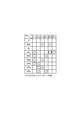
- the driving force of the internal combustion engine 2 is shifted between the first to sixth forward speeds and the reverse speed, and the driving force of the internal combustion engine 2 is transmitted to the wheels 80fl and 80fr. Note that the first forward speed to the sixth forward speed and the reverse speed of the automatic transmission 10 are as shown in the operation table shown in FIG. 3.
- Each clutch C-1 to C-3, brakes B-1 to B-2, The hydraulic servos 110, 120, 130, 150, etc. are operated so that the one-way clutch F-1 is operated (engaged control) (that is, the engagement pressure supplied to the hydraulic oil chamber of each hydraulic servo is reduced). Achieved by the supply state).
- the motor disconnection clutch CM shown in FIG. 1 is engaged, and the rear motor 20 is drivingly connected to the wheels 80rl and 80rr.
- the driving force of the rear motor 20 is appropriately assisted or regenerated based on the accelerator opening (driver's driving force request), that is, the driving force of the internal combustion engine 2 and the rear motor 20.
- the hybrid vehicle 100 is driven using the driving force.
- the motor disconnecting clutch CM When accelerating in the engine running mode by the driving force of the internal combustion engine 2, the motor disconnecting clutch CM is released, and the rear motor 20 is disconnected from the wheels 80rl and 80rr so as not to become running resistance. Also good. Even when the engine is running, it is preferable to improve the fuel consumption by engaging the motor separating clutch CM and executing the regenerative braking with the rear motor 20 during deceleration.
- the motor disconnection clutch CM shown in FIG. 1 is engaged, the rear motor 20 is drivingly connected to the wheels 80rl and 80rr, the internal combustion engine 2 is stopped, and neutral control described later is performed.
- the clutches C-2 to C-3 and the brakes B-1 to B-2 in the automatic transmission 10 are controlled to be released by the control of the hydraulic control device 6 by means 46 (see FIG. 4). It is made possible to idle (neutral state).
- the driving force of the rear motor 20 is appropriately powered or regenerated based on the accelerator opening (the driver's request for driving force), that is, the hybrid vehicle 100 travels using only the driving force of the rear motor 20.
- the control unit (TCU) 1 moves forward from the first forward speed based on, for example, the vehicle speed and the accelerator opening degree, as in Patent Document 1 (Japanese Patent Laid-Open No. 2010-223399).
- the engagement control of the clutch C-1 is prepared as preparation for transition from EV traveling to hybrid traveling.
- the automatic transmission mechanism 5 is in a towing state and is in a state similar to that at the time of engine braking, and the one-way clutch F-1 is idling, so that idling is possible. It is controlled to the state.
- the electric oil pump 32 also generates hydraulic pressure for controlling the engagement of the clutch C-1 in this way.
- the traveling state in which the control unit 1 determines that the vehicle travels from the fourth forward speed to the sixth forward speed based on the vehicle speed or the accelerator opening for example, during the EV traveling, the dragging of each clutch or brake in the high speed traveling is prevented.
- the clutch C-1, the clutch C-2, the clutch C-3, the brake B-1, and the brake B-2 are instructed to be released, and the automatic transmission mechanism 5 is controlled to be in the neutral state.
- the control of the clutch C-1 during EV traveling may be switched between the engagement control and the release control according to the determination of the vehicle speed instead of the determination of the shift speed.
- the brake B-1 is arranged to surround the clutch drum 132 due to the characteristics of a band brake, so that it is easily dragged by the drum portion of the clutch drum 132 during high-speed rotation.
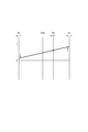
- the brake B-1 is dragged, as shown in the velocity diagram shown in FIG. 7, the rotation of the sun gear S2 is stopped as indicated by the arrow with respect to the rotation state of the ring gear R2 interlocked with the rotation of the wheels 80fl and 80fr. It will be in the form of receiving resistance.
- the sun gear S3 is rotated in the direction of rotating and rising as indicated by the arrow.
- the cancel oil chamber 115 from which more than half of the oil has escaped is gradually filled with the amount of lubricating oil supplied based on the hydraulic pressure generated by the electric oil pump 32, but is rapidly accelerated by the driving force of the rear motor 20.
- the amount of oil supplied to the cancel oil chamber 115 is insufficient and the rotation speed becomes high before the cancel oil chamber 115 is filled, the centrifugal oil pressure of the hydraulic oil chamber 114 and the cancel oil chamber 115 is reduced. Due to the differential pressure, there may occur a situation where the piston 113 is driven to be pressed in the direction in which the friction plate 111 is pressed.
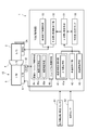
- the control unit (TCU) 1 is an electric motor having an elapsed time measuring means 41 having a timing stop means 41a, a vehicle speed detecting means 42, an oil temperature detecting means 43, an abnormality determining means 45a, and a failure determining means 45b.
- the oil pump control means 45, the neutral control means 46, the drag condition map 55, the drag determination means 51, the drag elimination control means 52, the elimination end control means 53, and the like are provided.
- An output shaft rotation (vehicle speed) sensor 61 that detects the rotation speed of the counter gear 11 (or the counter shaft 15) and an oil temperature sensor 62 that is disposed in the hydraulic control device 6 and detects the oil temperature, for example, are connected. Yes.
- the control unit 1 starts drag elimination control according to the present invention (S1), and first determines whether or not the vehicle is in EV travel (EV mode) ( S2).
- EV travel EV mode
- S2 EV travel
- No in S2 that is, when it is engine travel or hybrid travel, since the internal combustion engine 2 is driven, the mechanical oil pump 31 is driven to rotate, and the cancel oil chamber Since there is sufficient supply of lubricating oil to 115, the drag elimination control is not performed, and the process ends as it is (S12).
- the control unit 1 for example, when the oil temperature is lower than a predetermined temperature (for example, 0 degrees), etc., for example, even if the first forward speed is determined to be the third forward speed, the clutch C-1 is Release control is performed without engaging.
- the process proceeds to Step S4, and waits until EV traveling is started from the state where the hybrid vehicle 100 is stopped (No in S4).
- the vehicle speed detection means 42 that detects the vehicle speed V of the hybrid vehicle 100 based on the detection signal of the output shaft rotation (vehicle speed) sensor 61 detects that the vehicle speed V is not 0, it is determined as the start of EV travel (Yes in S4).
- the elapsed time measuring means 41 starts measuring the elapsed timer (S5). That is, the elapsed time measuring means 41 measures the elapsed time from the start of EV travel.
- the electric oil pump control means 45 should drive the electric oil pump 32 when the EV is running, but the abnormality determination means 45a determines whether or not an abnormality has occurred in the electric oil pump 32. (S6). Whether or not an abnormality has occurred in the electric oil pump 32 is, for example, a function of a driver installed in a computer provided in the electric oil pump 32, and an error signal is output from the driver. Based on the fact that a normal signal is output, it is determined normal (not abnormal). When the driver determines that the rotation is in the locked state or the idling state based on a change in the current value or voltage value with respect to the electric oil pump 32, the driver outputs an error signal.
- step S6 when it is determined by the abnormality determination means 45a that no abnormality has occurred in the electric oil pump 32 (No in S6), the process proceeds to step S7, and the elapsed time measurement means 41 starts from the start of EV travel. Continue measuring the elapsed time.
- step S6 when it is determined in step S6 that an abnormality has occurred in the electric oil pump 32 by the abnormality determination unit 45a (Yes in S6), first, the failure determination unit 45b determines that an abnormality has occurred in the electric oil pump 32.
- the count N is increased by 1 by setting the count N to N + 1 (S8), and it is determined whether or not the count N exceeds (or exceeds) the predetermined number ⁇ (S9).
- the count N which is the number of times the occurrence of the abnormality of the electric oil pump 32, is less than the predetermined number ⁇ (No in S9), the elapsed time from the start of the EV travel started in step S5. Is temporarily stopped (S10).
- the oil temperature detecting means 43 detects the oil temperature T of the lubricating oil based on the detection signal of the oil temperature sensor 62 (S11), and further, the vehicle speed detecting means 42 detects the vehicle speed V (S12), step. Proceed to S13.
- step S13 the drag determination means 51 detects “elapsed time t” of the elapsed timer started in step S5 (including the case where the elapsed timer is stopped in step S10), and “detected in step S6”. Based on “oil temperature T” and “vehicle speed V” detected in step S7, the drag condition map 55 is referred to and it is determined whether or not a condition for causing drag is satisfied.
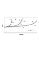
- the drag condition map 55 indicates that the “vehicle speed V” detected by the vehicle speed detection means 42 becomes smaller as the “elapsed time t” of the elapsed timer measured by the elapsed time measurement means 41 is shorter.
- oil temperature TA A dragging start boundary line corresponding to TB and TC is recorded.
- the position on the drag condition map 55 based on “elapsed time t”, “vehicle speed V”, and “oil temperature T” is higher than the drag start boundary lines corresponding to these oil temperatures TA, TB, and TC in the figure. If it is located on the left side, the drag condition is satisfied.
- the “elapsed time t” is not the elapsed time from the actual start of EV travel, but an abnormality occurs in the electric oil pump 32 and the electric oil pump 32, the time during which the oil could not be supplied to the cancel oil chamber 115 of the clutch C-1 is not added, that is, the accumulated time when the oil is supplied to the cancel oil chamber 115 of the clutch C-1 by the electric oil pump 32. It can be said.
- the range located above the dragging start boundary lines corresponding to the oil temperatures TA, TB, and TC in the drawing and on the left side is actually due to an insufficient amount of oil in the cancel oil chamber 115 of the clutch C-1.
- it is a boundary line that causes dragging, when the mechanical oil pump 31 is driven and oil is supplied to the cancel oil chamber 115 after the dragging is actually generated in the clutch C-1, the dragging to the clutch C-1 is performed during that time. Therefore, before the position based on the “elapsed time t”, “vehicle speed V”, and “oil temperature T” falls within the range of the dragging start boundary line, the drag elimination control described later is started in detail. It is preferable to do.
- the drag condition map 55 includes a safety for raising the internal combustion engine 2 to the idling speed with the belt-type integrated starter / generator 3A with respect to the drag start boundary lines corresponding to the oil temperatures TA, TB, and TC.
- Engine start boundary lines TAc, TBc, and TCc including a margin M are set.
- the drag determining means 51 determines the engine start boundary lines TAc, TBc, TCc as “a condition for predicting the occurrence of drag is satisfied”.
- the drag condition map 55 shown in FIG. 6 includes drag start boundary lines corresponding to three stages of oil temperatures TA, TB, and TC, and three stages of engine start boundary lines TAc, TBc, and TCc including a safety margin M.
- these boundary lines are appropriately set. It is preferable to determine that the drag generation condition is satisfied with the linearly complemented value.
- the amount of lubricating oil supplied to the cancel oil chamber 115 by the electric oil pump 32 is the acceleration performance of the hybrid vehicle 100 by the rear motor 20.
- the situation does not become insufficient, when the oil temperature is higher than the oil temperature TA, it can be handled that the drag does not occur, and it is not necessary to record the condition in the drag condition map 55. .
- the oil generated in the cancel oil chamber 115 is lubricated with the pressure generated by the electric oil pump 32 regardless of the elapsed time t. Therefore, the occurrence of dragging may be determined on the condition that the vehicle speed is higher than the constant vehicle speed V.
- the drag determination means 51 determines whether or not the drag generation condition is satisfied while referring to the drag condition map 55, and when the drag generation condition is not satisfied (No in S13), as shown in FIG.
- the process returns to step S6 again.
- the routine from step S6 to step S13 is performed at predetermined time intervals, that is, the determination of the occurrence of abnormality in the electric oil pump 32 in step S6 is performed at predetermined time intervals.
- step S6 if it is not determined that the electric oil pump 32 is abnormal (No in S6), the elapsed timer continues to be measured (or if the elapsed timer has been stopped in the previous step S10). The measurement of the elapsed timer is restarted) (S7), and the oil temperature T and the vehicle speed V are again detected (re-acquired) in steps S11 and S12.
- step S6 if it is determined in step S6 that the electric oil pump 32 is abnormal (Yes in S6), the count N is incremented by 1 (S8), and if the count N is less than the predetermined number ⁇ (S9). No), the measurement of the elapsed timer is continuously stopped (S10). As a result, the time measuring stop means 41a stops measuring the elapsed time by the elapsed time measuring means 41 while the abnormality determining means 45a determines that the electric oil pump 32 is abnormal.
- step S14 is performed as it is. Proceed to In this case, it is preferable that the internal combustion engine 2 is not stopped in step S17 to be described later, and the oil supply by the mechanical oil pump 31 is continued.
- the drag determination means 51 determines that the drag generation condition is satisfied (including the above-described condition where the occurrence of drag is predicted) while the routine from step S6 to step S13 is repeated ( As shown in FIG. 4, the drag elimination control means 52 instructs the belt-type integrated starter / generator 3A to start the internal combustion engine 2 (S14).
- the mechanical oil pump 31 (see FIG. 2) interlocked with the internal combustion engine 2 is rotationally driven, and the hydraulic pressure control device 6 generates a lubricating oil pressure larger than that when the electric oil pump 32 is driven.
- a large amount of lubricating oil is supplied, and the cancel oil chamber 115 is rapidly filled with oil.
- the cancellation end control means 53 starts measuring the start timer (S15), that is, starts measuring the time when the internal combustion engine 2 is driven. Then, the cancellation end control means 53 waits until the start timer reaches a predetermined time or longer (No in S16), and when it reaches the predetermined time or longer (Yes in S16), instructs to stop the fuel injection of the internal combustion engine 2. Then, the driving state of the internal combustion engine 2 is released (S17), and the drag elimination control is finished (S18).
- the predetermined time (start timer) is a time until the cancel oil chamber 115 is sufficiently filled by driving the mechanical oil pump 31, and is about several seconds (for example, about 2 to 3 seconds).
- step S17 the release of the driving state of the internal combustion engine 2 in step S17 is performed by transmitting a status signal permitting the stop of the internal combustion engine 2 to the internal combustion engine 2 instead of the above-described instruction to stop the fuel injection. May be determined.
- the drag determination means 51 causes the clutch C to run out of the amount of oil supplied to the cancel oil chamber 115 of the clutch C- 1 by the electric oil pump 32 during EV traveling.
- the drag elimination control means 52 commands the start of the internal combustion engine 2 to rotationally drive the mechanical oil pump 31, so that the clutch C-1 When dragging occurs (when the occurrence is predicted), a large amount of oil from the mechanical oil pump 31 can be supplied to the cancel oil chamber 115 of the clutch C-1, and the clutch C-1 Generation of drag can be prevented. Since the occurrence of drag can be prevented in this way, the electric oil pump 32 can be reduced in size as compared with the case where the occurrence of drag is prevented with a large electric oil pump, which improves vehicle mounting performance and reduces costs. Can be achieved.
- condition for causing the drag is set so that the longer the elapsed time t from the start of EV travel and the higher the vehicle speed V is, the easier it is to be established.
- the occurrence (prediction) of dragging of the clutch C-1 can be accurately determined in accordance with the amount of oil supplied to one canceling oil chamber 115.
- the conditions for causing drag are set such that the lower the oil temperature T, the easier the condition is established. Therefore, the oil to the cancel oil chamber 115 of the clutch C-1 by the electric oil pump 32 that changes according to the oil temperature T is set.
- the occurrence (prediction) of dragging of the clutch C-1 can be accurately determined in accordance with the amount of supply. Thus, while unnecessary starting of the internal combustion engine 2 can be prevented, when dragging occurs in the clutch C-1 (when generation is predicted), the dragging in the clutch C-1 is appropriately performed. Occurrence can be prevented.
- the drag generation condition is set so as to include, as the safety margin M, the time required to reach the idling engine speed after the internal combustion engine 2 is started, before the drag is generated in the clutch C-1.
- the start of the internal combustion engine 2 can be completed, and the occurrence of dragging in the clutch C-1 can be reliably prevented.
- the electric oil pump 32 is abnormal and there is a possibility that the electric oil pump 32 is not supplying oil to the cancel oil chamber 115 of the clutch C-1 during EV traveling, the elapsed timer is measured. Therefore, the condition that the drag is generated in the clutch C-1 can be satisfied by taking into account the abnormality occurrence time of the electric oil pump 32, and it is assumed that the abnormality occurs in the electric oil pump 32. In addition, the occurrence of dragging in the clutch C-1 can be reliably prevented.
- the engine oil is commanded to start and mechanical oil is supplied. Since the pump 31 is rotationally driven, the mechanical oil pump 31 is reliably driven when the electric oil pump 32 fails, and the occurrence of dragging in the clutch C-1 can be reliably prevented.
- the cancellation end control means 53 commands the stop of the internal combustion engine 2 after a predetermined time since the drag cancellation control means 52 commands the start of the internal combustion engine 2, the cancel oil chamber 115 of the clutch C-1 is oiled. It is possible to prevent the internal combustion engine 2 from being wastefully driven after being satisfied.
- the present invention is not limited to this, and the automatic transmission is mounted and the EV is running.
- the present invention can be applied to any hybrid vehicle as long as the amount of oil supplied to the cancel oil chamber of the friction engagement element by the electric oil pump can be insufficient.
- the hybrid vehicle is a concept including a plug-in hybrid vehicle that can run on EV by charging.
- the automatic transmission 10 is a multi-stage automatic transmission that achieves the sixth forward speed and the reverse speed.
- the present invention is not limited to this.
- the present invention can also be applied to a multi-stage transmission having a lower speed or a continuously variable transmission that performs a continuously variable transmission of a belt type, a toroidal type, or a ring cone type.
- the hydraulic servo 110 of the clutch C-1 is rotated during EV travel to generate dragging.
- the present invention is not limited to the clutch C-1, and is canceled by other friction engagement elements.
- the present invention can be applied to the frictional engagement element.
- the engine start boundary lines TAc, TBc, and TCc of the drag condition map shown in FIG. 6 are set to the vehicle speed V or the elapsed time t as the meaning of “determining that the condition for generating drag is satisfied”. Is determined based on whether or not the engine has exceeded, that is, it means that “the occurrence of dragging is predicted and determined” for the amount of time during which the internal combustion engine 2 is increased to the idle speed, but is not limited thereto. , Or "means that it is determined that dragging has actually occurred”. That is, it may be “determined that dragging has occurred” at “the dragging start boundary lines corresponding to the oil temperatures TA, TB, TC” shown in FIG. A change in rotational acceleration or the like may be detected, and as a result, “determining that dragging has actually occurred” may be used.
- the clutch C-1 is engaged when the first forward speed or the third forward speed is determined during EV traveling.
- the clutch and the brake may be completely released, and the automatic transmission 10 may always be in the neutral state.
- the control apparatus for an automatic transmission for a hybrid vehicle can be used for a hybrid vehicle such as a passenger car and a truck, and in particular, prevents dragging of a friction engagement element during EV traveling, and an electric oil pump It is suitable for use in those that require downsizing.
- Hybrid vehicle automatic transmission control device (control unit) 2 Internal combustion engine 10 Automatic transmission for hybrid vehicle (automatic transmission) 20 Rotating electric machine (motor) 31 Mechanical oil pump 32 Electric oil pump 41 Elapsed time measuring means 41a Timing stop means 42 Vehicle speed detecting means 43 Oil temperature detecting means 45a Abnormality determining means 45b Failure determining means 51 Drag determining means 52 Drag elimination control means 53 Resolution termination control means 100 Vehicle (hybrid vehicle) 115 Cancellation oil chamber C-1 Friction engagement element (clutch) C-2 Friction engagement element (clutch) C-3 Friction engagement element (clutch) B-1 Friction engagement element (brake) B-2 Friction engagement element (brake) M Safety margin N Number of occurrences of abnormality T Oil temperature V Vehicle speed t Elapsed time ⁇ Predetermined number
Landscapes
- Engineering & Computer Science (AREA)
- Mechanical Engineering (AREA)
- Transportation (AREA)
- Chemical & Material Sciences (AREA)
- Combustion & Propulsion (AREA)
- General Engineering & Computer Science (AREA)
- Automation & Control Theory (AREA)
- Hybrid Electric Vehicles (AREA)
- Control Of Transmission Device (AREA)
- General Details Of Gearings (AREA)
- Electric Propulsion And Braking For Vehicles (AREA)
Priority Applications (4)
| Application Number | Priority Date | Filing Date | Title |
|---|---|---|---|
| CN201280067027.1A CN104039621B (zh) | 2012-03-23 | 2012-12-26 | 混合动力车辆用自动变速器的控制装置 |
| DE112012005294.3T DE112012005294B4 (de) | 2012-03-23 | 2012-12-26 | Steuervorrichtung für ein Automatikgetriebe eines Hybridfahrzeugs |
| US14/379,001 US9327711B2 (en) | 2012-03-23 | 2012-12-26 | Control device and control method for automatic transmission |
| JP2014505975A JP5839110B2 (ja) | 2012-03-23 | 2012-12-26 | ハイブリッド車両用自動変速機の制御装置 |
Applications Claiming Priority (2)
| Application Number | Priority Date | Filing Date | Title |
|---|---|---|---|
| JP2012068139 | 2012-03-23 | ||
| JP2012-068139 | 2012-03-23 |
Publications (1)
| Publication Number | Publication Date |
|---|---|
| WO2013140696A1 true WO2013140696A1 (fr) | 2013-09-26 |
Family
ID=49222182
Family Applications (1)
| Application Number | Title | Priority Date | Filing Date |
|---|---|---|---|
| PCT/JP2012/083687 Ceased WO2013140696A1 (fr) | 2012-03-23 | 2012-12-26 | Dispositif de commande pour transmission automatique de véhicule hybride |
Country Status (5)
| Country | Link |
|---|---|
| US (1) | US9327711B2 (fr) |
| JP (1) | JP5839110B2 (fr) |
| CN (1) | CN104039621B (fr) |
| DE (1) | DE112012005294B4 (fr) |
| WO (1) | WO2013140696A1 (fr) |
Cited By (3)
| Publication number | Priority date | Publication date | Assignee | Title |
|---|---|---|---|---|
| CN111284479A (zh) * | 2018-11-22 | 2020-06-16 | 丰田自动车株式会社 | 混合动力车辆的控制装置 |
| WO2020166587A1 (fr) * | 2019-02-14 | 2020-08-20 | アイシン・エィ・ダブリュ株式会社 | Dispositif de commande pour dispositif d'entraînement de véhicule |
| US11097738B2 (en) | 2019-06-14 | 2021-08-24 | Toyota Jidosha Kabushiki Kaisha | Control apparatus for vehicle |
Families Citing this family (7)
| Publication number | Priority date | Publication date | Assignee | Title |
|---|---|---|---|---|
| DE102013107330B4 (de) * | 2013-07-11 | 2024-06-20 | Dr. Ing. H.C. F. Porsche Aktiengesellschaft | Verfahren und Vorrichtung zum Antreiben eines Kraftfahrzeugs mit Hybridantrieb |
| JP6044569B2 (ja) * | 2014-03-12 | 2016-12-14 | 株式会社デンソー | 制御装置 |
| DE102015215543A1 (de) * | 2015-08-14 | 2017-02-16 | Zf Friedrichshafen Ag | Antriebsstrang für ein Kraftfahrzeug, sowie Verfahren zum Betrieb eines Kraftfahrzeuges |
| KR101786206B1 (ko) * | 2015-10-20 | 2017-10-18 | 현대자동차주식회사 | 변속기의 eop 제어방법 |
| JP7343428B2 (ja) * | 2020-03-16 | 2023-09-12 | トヨタ自動車株式会社 | ハイブリッド車両の駆動装置 |
| CN113494407B (zh) * | 2020-04-08 | 2022-08-16 | 广州汽车集团股份有限公司 | 一种基于电机调速的发动机启动控制 |
| JP7767039B2 (ja) * | 2021-06-24 | 2025-11-11 | 株式会社ミクニ | オイルポンプ装置 |
Citations (7)
| Publication number | Priority date | Publication date | Assignee | Title |
|---|---|---|---|---|
| JP2000035122A (ja) * | 1998-05-15 | 2000-02-02 | Toyota Motor Corp | 車両のエンジン再始動時の制御装置 |
| JP2004364432A (ja) * | 2003-06-05 | 2004-12-24 | Toyota Motor Corp | ハイブリッド車の制御装置 |
| JP2005207303A (ja) * | 2004-01-22 | 2005-08-04 | Toyota Motor Corp | ハイブリッド車の制御装置 |
| JP2005349916A (ja) * | 2004-06-09 | 2005-12-22 | Nissan Motor Co Ltd | 四輪駆動車の従駆動輪駆動ユニット制御装置 |
| JP2008290613A (ja) * | 2007-05-25 | 2008-12-04 | Honda Motor Co Ltd | ハイブリッド車両の駆動装置 |
| JP2009058000A (ja) * | 2007-08-30 | 2009-03-19 | Toyota Motor Corp | 車両用油圧式摩擦係合装置の制御装置 |
| JP2010223399A (ja) * | 2009-03-25 | 2010-10-07 | Aisin Aw Co Ltd | 車両用制御装置及び車両駆動システム |
Family Cites Families (17)
| Publication number | Priority date | Publication date | Assignee | Title |
|---|---|---|---|---|
| DE69926269T2 (de) | 1998-04-17 | 2006-05-04 | Toyota Jidosha K.K., Toyota | Steuerungsvorrichtung zur Startwiederholung eines Fahrzeugsmotors |
| JP4142862B2 (ja) * | 2000-11-13 | 2008-09-03 | 本田技研工業株式会社 | ハイブリッド車両における変速機の制御装置 |
| JP3551178B2 (ja) * | 2001-09-10 | 2004-08-04 | 日産自動車株式会社 | 車両のクラッチ制御装置 |
| JP3574121B2 (ja) | 2002-08-07 | 2004-10-06 | 本田技研工業株式会社 | ハイブリッド車両のエンジン停止始動制御装置 |
| JP4249147B2 (ja) | 2005-02-18 | 2009-04-02 | 本田技研工業株式会社 | ハイブリッド車両の電動オイルポンプ制御装置 |
| JP4185922B2 (ja) * | 2005-06-03 | 2008-11-26 | ジヤトコ株式会社 | クラッチ制御装置及びクラッチ制御方法 |
| CN101037087A (zh) * | 2006-03-14 | 2007-09-19 | 朱荣辉 | 一种机动车无级变速混合动力节能装置 |
| JP2008155802A (ja) * | 2006-12-25 | 2008-07-10 | Toyota Motor Corp | 車両用駆動装置の制御装置 |
| JP4997986B2 (ja) * | 2007-01-19 | 2012-08-15 | トヨタ自動車株式会社 | ハイブリッド車両の制御装置 |
| JP4447027B2 (ja) * | 2007-08-07 | 2010-04-07 | トヨタ自動車株式会社 | 車両用動力伝達装置の制御装置 |
| WO2009152793A1 (fr) * | 2008-06-19 | 2009-12-23 | Luk Lamellen Und Kupplungsbau Beteiligungs Kg | Dispositif d'accouplement commutable, en particulier accouplement humide par friction, chaîne cinématique pour un système hybride, procédé d'exploitation d'une telle chaîne cinématique et véhicule équipé d'une telle chaîne cinématique |
| US8370051B2 (en) * | 2009-01-05 | 2013-02-05 | Ford Global Technologies, Llc | Methods and systems for assisted direct start control |
| JP5144805B2 (ja) * | 2009-04-10 | 2013-02-13 | トヨタ自動車株式会社 | 車両用駆動装置の制御装置 |
| JP5249976B2 (ja) * | 2010-03-05 | 2013-07-31 | アイシン・エィ・ダブリュ株式会社 | ハイブリッド駆動装置 |
| JP5429563B2 (ja) * | 2010-03-25 | 2014-02-26 | アイシン・エィ・ダブリュ株式会社 | 車両用制御装置及び車両駆動システム |
| JP5622038B2 (ja) * | 2010-09-06 | 2014-11-12 | アイシン・エィ・ダブリュ株式会社 | 制御装置 |
| DE102012211674B4 (de) | 2012-07-05 | 2024-09-26 | Zf Friedrichshafen Ag | Verfahren zum Betreiben eines Parallelhybridantriebsstranges eines Fahrzeuges |
-
2012
- 2012-12-26 WO PCT/JP2012/083687 patent/WO2013140696A1/fr not_active Ceased
- 2012-12-26 US US14/379,001 patent/US9327711B2/en active Active
- 2012-12-26 JP JP2014505975A patent/JP5839110B2/ja not_active Expired - Fee Related
- 2012-12-26 DE DE112012005294.3T patent/DE112012005294B4/de not_active Expired - Fee Related
- 2012-12-26 CN CN201280067027.1A patent/CN104039621B/zh not_active Expired - Fee Related
Patent Citations (7)
| Publication number | Priority date | Publication date | Assignee | Title |
|---|---|---|---|---|
| JP2000035122A (ja) * | 1998-05-15 | 2000-02-02 | Toyota Motor Corp | 車両のエンジン再始動時の制御装置 |
| JP2004364432A (ja) * | 2003-06-05 | 2004-12-24 | Toyota Motor Corp | ハイブリッド車の制御装置 |
| JP2005207303A (ja) * | 2004-01-22 | 2005-08-04 | Toyota Motor Corp | ハイブリッド車の制御装置 |
| JP2005349916A (ja) * | 2004-06-09 | 2005-12-22 | Nissan Motor Co Ltd | 四輪駆動車の従駆動輪駆動ユニット制御装置 |
| JP2008290613A (ja) * | 2007-05-25 | 2008-12-04 | Honda Motor Co Ltd | ハイブリッド車両の駆動装置 |
| JP2009058000A (ja) * | 2007-08-30 | 2009-03-19 | Toyota Motor Corp | 車両用油圧式摩擦係合装置の制御装置 |
| JP2010223399A (ja) * | 2009-03-25 | 2010-10-07 | Aisin Aw Co Ltd | 車両用制御装置及び車両駆動システム |
Cited By (4)
| Publication number | Priority date | Publication date | Assignee | Title |
|---|---|---|---|---|
| CN111284479A (zh) * | 2018-11-22 | 2020-06-16 | 丰田自动车株式会社 | 混合动力车辆的控制装置 |
| CN111284479B (zh) * | 2018-11-22 | 2023-04-07 | 丰田自动车株式会社 | 混合动力车辆的控制装置 |
| WO2020166587A1 (fr) * | 2019-02-14 | 2020-08-20 | アイシン・エィ・ダブリュ株式会社 | Dispositif de commande pour dispositif d'entraînement de véhicule |
| US11097738B2 (en) | 2019-06-14 | 2021-08-24 | Toyota Jidosha Kabushiki Kaisha | Control apparatus for vehicle |
Also Published As
| Publication number | Publication date |
|---|---|
| JP5839110B2 (ja) | 2016-01-06 |
| JPWO2013140696A1 (ja) | 2015-08-03 |
| US9327711B2 (en) | 2016-05-03 |
| DE112012005294B4 (de) | 2022-01-27 |
| CN104039621A (zh) | 2014-09-10 |
| DE112012005294T5 (de) | 2014-09-04 |
| CN104039621B (zh) | 2016-08-17 |
| US20150032316A1 (en) | 2015-01-29 |
Similar Documents
| Publication | Publication Date | Title |
|---|---|---|
| JP5839110B2 (ja) | ハイブリッド車両用自動変速機の制御装置 | |
| JP5799873B2 (ja) | ハイブリッド車両の制御装置 | |
| US8715135B2 (en) | Control device for hybrid vehicle automatic transmission | |
| JP3915698B2 (ja) | ハイブリッド車輌の制御装置 | |
| US9643608B2 (en) | Vehicular power transmission device | |
| US11052903B2 (en) | Hybrid vehicle drive system | |
| JP5888429B2 (ja) | ハイブリッド車両の始動制御装置 | |
| CN105190109B (zh) | 油供应装置 | |
| JP4207376B2 (ja) | 車両の油圧制御装置 | |
| JPWO2012101791A1 (ja) | ハイブリッド車両の制御装置 | |
| WO2014091588A1 (fr) | Dispositif de commande pour véhicule hybride | |
| WO2014147920A1 (fr) | Dispositif de commande du débit de lubrifiant pour une transmission automatique, et procédé de commande du débit de lubrifiant | |
| US11173915B2 (en) | Hybrid vehicle drive apparatus | |
| JP2013203140A (ja) | ハイブリッド車両用自動変速機の制御装置 | |
| JP2014073747A (ja) | ハイブリッド車両の始動制御装置 | |
| JP2004056899A (ja) | 車両制御装置 | |
| JP5807590B2 (ja) | ハイブリッド車両用自動変速機の制御装置 | |
| JP6465204B2 (ja) | 車両用駆動装置の制御装置 | |
| JP2000166023A (ja) | ハイブリッド車のモ―タジェネレ―タ制御装置 | |
| JP2013136277A (ja) | 車輌用駆動装置 | |
| JP2013216144A (ja) | ハイブリッド電気自動車のクラッチ制御装置 | |
| JP2010117032A (ja) | 車両用自動変速機の制御装置 | |
| JP2005009590A (ja) | 変速機の異常検出装置 | |
| JP4182607B2 (ja) | 蓄エネ用フライホイールを有する車両の制御装置 | |
| JP3931809B2 (ja) | 車輌の制御装置 |
Legal Events
| Date | Code | Title | Description |
|---|---|---|---|
| 121 | Ep: the epo has been informed by wipo that ep was designated in this application |
Ref document number: 12871874 Country of ref document: EP Kind code of ref document: A1 |
|
| ENP | Entry into the national phase |
Ref document number: 2014505975 Country of ref document: JP Kind code of ref document: A |
|
| WWE | Wipo information: entry into national phase |
Ref document number: 112012005294 Country of ref document: DE Ref document number: 1120120052943 Country of ref document: DE |
|
| WWE | Wipo information: entry into national phase |
Ref document number: 14379001 Country of ref document: US |
|
| 122 | Ep: pct application non-entry in european phase |
Ref document number: 12871874 Country of ref document: EP Kind code of ref document: A1 |