WO2013140717A2 - Procédé de fabrication d'un élément optique, élément optique, et appareil de capture d'image - Google Patents
Procédé de fabrication d'un élément optique, élément optique, et appareil de capture d'image Download PDFInfo
- Publication number
- WO2013140717A2 WO2013140717A2 PCT/JP2013/001109 JP2013001109W WO2013140717A2 WO 2013140717 A2 WO2013140717 A2 WO 2013140717A2 JP 2013001109 W JP2013001109 W JP 2013001109W WO 2013140717 A2 WO2013140717 A2 WO 2013140717A2
- Authority
- WO
- WIPO (PCT)
- Prior art keywords
- glass
- glass layer
- optical member
- porous
- equal
- Prior art date
- Legal status (The legal status is an assumption and is not a legal conclusion. Google has not performed a legal analysis and makes no representation as to the accuracy of the status listed.)
- Ceased
Links
Images





Classifications
-
- C—CHEMISTRY; METALLURGY
- C03—GLASS; MINERAL OR SLAG WOOL
- C03C—CHEMICAL COMPOSITION OF GLASSES, GLAZES OR VITREOUS ENAMELS; SURFACE TREATMENT OF GLASS; SURFACE TREATMENT OF FIBRES OR FILAMENTS MADE FROM GLASS, MINERALS OR SLAGS; JOINING GLASS TO GLASS OR OTHER MATERIALS
- C03C11/00—Multi-cellular glass ; Porous or hollow glass or glass particles
- C03C11/005—Multi-cellular glass ; Porous or hollow glass or glass particles obtained by leaching after a phase separation step
-
- C—CHEMISTRY; METALLURGY
- C03—GLASS; MINERAL OR SLAG WOOL
- C03C—CHEMICAL COMPOSITION OF GLASSES, GLAZES OR VITREOUS ENAMELS; SURFACE TREATMENT OF GLASS; SURFACE TREATMENT OF FIBRES OR FILAMENTS MADE FROM GLASS, MINERALS OR SLAGS; JOINING GLASS TO GLASS OR OTHER MATERIALS
- C03C17/00—Surface treatment of glass, not in the form of fibres or filaments, by coating
- C03C17/006—Surface treatment of glass, not in the form of fibres or filaments, by coating with materials of composite character
- C03C17/007—Surface treatment of glass, not in the form of fibres or filaments, by coating with materials of composite character containing a dispersed phase, e.g. particles, fibres or flakes, in a continuous phase
-
- C—CHEMISTRY; METALLURGY
- C03—GLASS; MINERAL OR SLAG WOOL
- C03C—CHEMICAL COMPOSITION OF GLASSES, GLAZES OR VITREOUS ENAMELS; SURFACE TREATMENT OF GLASS; SURFACE TREATMENT OF FIBRES OR FILAMENTS MADE FROM GLASS, MINERALS OR SLAGS; JOINING GLASS TO GLASS OR OTHER MATERIALS
- C03C17/00—Surface treatment of glass, not in the form of fibres or filaments, by coating
- C03C17/02—Surface treatment of glass, not in the form of fibres or filaments, by coating with glass
- C03C17/04—Surface treatment of glass, not in the form of fibres or filaments, by coating with glass by fritting glass powder
-
- C—CHEMISTRY; METALLURGY
- C03—GLASS; MINERAL OR SLAG WOOL
- C03C—CHEMICAL COMPOSITION OF GLASSES, GLAZES OR VITREOUS ENAMELS; SURFACE TREATMENT OF GLASS; SURFACE TREATMENT OF FIBRES OR FILAMENTS MADE FROM GLASS, MINERALS OR SLAGS; JOINING GLASS TO GLASS OR OTHER MATERIALS
- C03C3/00—Glass compositions
- C03C3/04—Glass compositions containing silica
- C03C3/076—Glass compositions containing silica with 40% to 90% silica, by weight
- C03C3/089—Glass compositions containing silica with 40% to 90% silica, by weight containing boron
- C03C3/091—Glass compositions containing silica with 40% to 90% silica, by weight containing boron containing aluminium
- C03C3/093—Glass compositions containing silica with 40% to 90% silica, by weight containing boron containing aluminium containing zinc or zirconium
-
- C—CHEMISTRY; METALLURGY
- C03—GLASS; MINERAL OR SLAG WOOL
- C03C—CHEMICAL COMPOSITION OF GLASSES, GLAZES OR VITREOUS ENAMELS; SURFACE TREATMENT OF GLASS; SURFACE TREATMENT OF FIBRES OR FILAMENTS MADE FROM GLASS, MINERALS OR SLAGS; JOINING GLASS TO GLASS OR OTHER MATERIALS
- C03C8/00—Enamels; Glazes; Fusion seal compositions being frit compositions having non-frit additions
- C03C8/02—Frit compositions, i.e. in a powdered or comminuted form
-
- C—CHEMISTRY; METALLURGY
- C03—GLASS; MINERAL OR SLAG WOOL
- C03C—CHEMICAL COMPOSITION OF GLASSES, GLAZES OR VITREOUS ENAMELS; SURFACE TREATMENT OF GLASS; SURFACE TREATMENT OF FIBRES OR FILAMENTS MADE FROM GLASS, MINERALS OR SLAGS; JOINING GLASS TO GLASS OR OTHER MATERIALS
- C03C8/00—Enamels; Glazes; Fusion seal compositions being frit compositions having non-frit additions
- C03C8/14—Glass frit mixtures having non-frit additions, e.g. opacifiers, colorants, mill-additions
- C03C8/16—Glass frit mixtures having non-frit additions, e.g. opacifiers, colorants, mill-additions with vehicle or suspending agents, e.g. slip
-
- C—CHEMISTRY; METALLURGY
- C03—GLASS; MINERAL OR SLAG WOOL
- C03C—CHEMICAL COMPOSITION OF GLASSES, GLAZES OR VITREOUS ENAMELS; SURFACE TREATMENT OF GLASS; SURFACE TREATMENT OF FIBRES OR FILAMENTS MADE FROM GLASS, MINERALS OR SLAGS; JOINING GLASS TO GLASS OR OTHER MATERIALS
- C03C2217/00—Coatings on glass
- C03C2217/40—Coatings comprising at least one inhomogeneous layer
- C03C2217/425—Coatings comprising at least one inhomogeneous layer consisting of a porous layer
Definitions
- the present invention relates to a method for manufacturing an optical member having a porous glass layer on a substrate, an optical member manufactured by the manufacturing method, and an image pickup apparatus including the optical member.
- porous glasses in industrial applications has been anticipated, such as as adsorbents, microcarriers, separator membranes, and optical materials.
- porous glasses can be widely used as materials of optical members.
- Porous glasses can be relatively easily manufactured by a process utilizing phase separation.
- the base material of porous glasses manufactured by utilizing phase separation is generally borosilicate glass.
- the raw materials of borosilicate glass include silicon oxide, boron trioxide, and alkali metal oxides.
- Shaped borosilicate glass is heat-treated at a constant temperature to induce phase separation (hereinafter referred to as phase separation treatment).
- phase separation treatment A soluble non-silicon-oxide-rich phase is etched with an acid solution.
- the skeleton of porous glass thus manufactured is mainly composed of silicon oxide.
- the skeleton size, the pore size, and the porosity of porous glass affect the light reflectance and refractive index of the porous glass.
- PTL 1 and PTL 2 disclose a method for forming a porous glass layer on a substrate. More specifically, a glass paste is applied to a substrate, is fired to form a mother glass layer, and is subjected to phase separation heat treatment and etching to form a porous glass layer on the substrate.
- the film uniformity may be improved by using high energy for fusion.
- high energy also contributes to the crystallization of silicon oxide and crystallization in the glass film.
- the presence of crystals in a porous glass film results in a large difference in refractive index between the crystals and the other portion, thereby increasing scattering.
- the present invention provides a method for easily manufacturing an optical member having a porous glass layer on a substrate and causing less scattering.
- a method for manufacturing an optical member having a porous glass layer on a substrate includes forming a glass powder layer containing a plurality of glass powders on the substrate, fusing the glass powders in the glass powder layer to form a mother glass layer containing silicon and aluminum, causing phase separation of the mother glass layer to form a phase-separated glass layer, and etching the phase-separated glass layer to form a porous glass layer.
- the fusion index M and the ratio A of aluminum to silicon of the mother glass layer in the forming of the mother glass layer satisfy the following relations: M is more than or equal to 50, A is more than or equal to 0.005 and less than or equal to 0.090, and M/A is less than or equal to 13500.
- the present invention provides a method for easily manufacturing an optical member having a porous glass layer on a substrate and causing less scattering.
- Fig. 1 is a graph of the relationship between the fusion index M and the ratio A of aluminum to silicon of a mother glass layer according to an embodiment of the present invention.
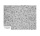
- Fig. 2 is a photograph of voids in a porous glass film.
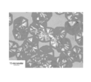
- Fig. 3 is a photograph of crystals in a porous glass film.
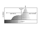
- Fig. 4 is a graph illustrating porosity.
- Fig. 5A is a photograph for illustrating the average pore size and the average skeleton size.
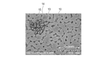
- Fig. 5B is a photograph for illustrating the average pore size and the average skeleton size.
- Fig. 6 is a schematic view of an image pickup apparatus including an optical member according to an embodiment of the present invention.
- Fig. 6 is a schematic view of an image pickup apparatus including an optical member according to an embodiment of the present invention.
- FIG. 7A is a schematic view illustrating a method for manufacturing an optical member according to an embodiment of the present invention.
- Fig. 7B is a schematic view illustrating a method for manufacturing an optical member according to an embodiment of the present invention.
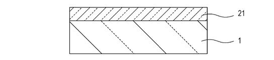
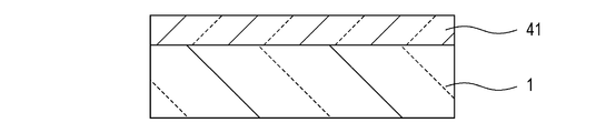
- Fig. 7C is a schematic view illustrating a method for manufacturing an optical member according to an embodiment of the present invention.
- Fig. 7D is a schematic view illustrating a method for manufacturing an optical member according to an embodiment of the present invention.
- Fig. 8 is a graph showing the dependence of reflectance on wavelength in Examples 1 to 7 and Comparative Examples 1 to 4.
- Phase separation for forming a porous structure in the present invention will be described below using borosilicate glass that contains silicon oxide, boron trioxide, and an alkali metal oxide as glass.
- Phase separation refers to separation between a phase containing increased amounts of alkali metal oxide and boron trioxide in glass after the phase separation (a non-silicon-oxide-rich phase) and another phase containing reduced amounts of alkali metal oxide and boron trioxide in glass after the phase separation (a silicon-oxide-rich phase). These phases have a structure in the range of several nanometers to several tens of micrometers.
- the non-silicon-oxide-rich phase in glass after phase separation is removed by etching to form a porous structure in the glass.
- Phase separation includes spinodal and binodal phase separation.
- Porous glass manufactured by spinodal phase separation has through-holes extending from the surface to the interior. More specifically, a structure resulting from spinodal phase separation is a "formicary" structure having three-dimensionally interconnected pores, in which a silicon oxide skeleton forms "walls", and the through-holes correspond to "interconnected pores”.
- Porous glass manufactured by binodal phase separation includes discrete closed pores, which are similar to spheres, each surrounded by a closed surface in a silicon oxide skeleton.
- Pores resulting from spinodal phase separation and pores resulting from binodal phase separation can be differentiated by morphological observation with an electron microscope. Whether spinodal phase separation or binodal phase separation depends on the composition of glass and phase separation temperature.
- the present invention utilizes spinodal phase separation.
- a porous structure resulting from spinodal phase separation has a three-dimensional network of through-holes extending inward from the surface and has porosity that depends on the heat-treatment conditions.
- the porous structure has a three-dimensional intricate network and can therefore have a high strength even at high porosity. Since the porous structure can have a high surface strength even at high porosity, it is possible to provide an optical member that has excellent antireflection performance and high scratch resistance.
- an optical member includes a porous glass layer 41 on a substrate 1.
- the porous glass layer 41 has a continuous porous structure resulting from spinodal phase separation.
- the porous glass layer 41 has a low refractive index and can reduce reflection from the interface between the porous glass layer 41 and air (the top surface of the porous glass layer 41).
- the porous glass layer 41 is expected to be utilized in an optical member.
- the porosity of the porous glass layer 41 is preferably 20% or more and 70% or less, more preferably 20% or more and 60% or less. A porosity of less than 20% unfavorably results in an insufficient advantage of porosity. A porosity of more than 70% also unfavorably results in a low surface strength.
- the porosity of a porous glass layer of 20% or more and 70% or less corresponds to the refractive index of 1.10 or more and 1.40 or less.
- the porosity can be measured by the following method.
- An electron micrograph image is binarized with respect to a skeleton and pores. More specifically, the surface of the porous glass layer 41 is observed with a scanning electron microscope (FE-SEM S-4800, manufactured by Hitachi, Ltd.) at an accelerating voltage of 5.0 kV at a magnification of 100,000 (or 50,000) at which it is easy to observe the skeleton on a gray scale.
- the observed SEM image is stored and is converted into a graph with image analysis software in accordance with optical density.
- Fig. 4 is a graph illustrating the occurrence of pores in a spinodal porous structure as a function of optical density. The optical density at the peak indicated by the down arrow in Fig.
- a bright portion (skeleton) and a dark portion (pores) are binarized into black and white using an inflection point close to the peak as a threshold.
- the ratio of a black area to the entire area (the total of white and black areas) is determined for each of the black areas in the image. The ratios are averaged to determine porosity.
- the thickness of the porous glass layer 41 is, but not limited to, preferably 0.2 micrometers or more and 50.0 micrometers or less, more preferably 0.2 micrometers or more and 10 micrometers or less.
- a high porosity a low refractive index
- the porous glass layer 41 is difficult to treat as an optical member because of scattering.
- the thickness of the porous glass layer 41 is determined as follows: a SEM image (electron micrograph) is taken with a scanning electron microscope (FE-SEMS-4800, manufactured by Hitachi, Ltd.) at an accelerating voltage of 5.0 kV. The thickness of the porous glass layer 41 on the substrate 1 is a mean value of measurements at 30 or more points on the image.
- One or more porous glass layers may be stacked on the porous glass layer 41. With an increase in porosity from the substrate 1 to the top surface of the porous glass layers, the porous glass layers can have a lower reflectance as a whole.
- An optical member according to an embodiment of the present invention may include a non-porous film on the porous glass layer 41.
- the non-porous film has a lower refractive index than the porous glass layer 41.
- a gradient layer having gradient refractive indexes may be disposed between the substrate 1 and the porous glass layer 41.
- the gradient layer is made of a porous film and has gradient porosities in the thickness direction.
- the gradient layer may be composed of a plurality of porous films having different porosities. In both cases, for use in an optical member, the porosity must increase from the substrate 1 to the porous glass layer 41.
- the average pore size of the porous glass layer 41 is preferably 1 nm or more and 100 nm or less, more preferably 5 nm or more and 50 nm or less, still more preferably 5 nm or more and 20 nm or less.
- the porous glass layer 2 having an average pore size of less than 1 nm cannot take advantage of the porous structure.
- An average pore size of more than 100 nm may unfavorably result in a low surface strength.
- An average pore size of 20 nm or less advantageously results in markedly reduced light scattering.
- the average pore size can be smaller than the thickness of the porous glass layer 41.
- average pore size refers to the mean length of the minor axes of ellipses each corresponding to a pore in a porous body surface. More specifically, as illustrated in Fig. 5A, the average pore size can be determined by calculating the mean length of the minor axes 12 of ellipses 11 each corresponding to a pore 10 in an electron micrograph of a porous body surface. The average pore size is determined from at least 30 measurements.
- the average skeleton size of the porous glass layer 41 is preferably 1 nm or more and 500 nm or less, more preferably 5 nm or more and 50 nm or less, still more preferably 5 nm or more and 20 nm or less.
- An average skeleton size of more than 100 nm results in marked light scattering and much reduced transmittance.
- An average skeleton size of less than 1 nm may result in a low strength of the porous glass layer 41.
- An average skeleton size of more than 500 nm results in poor denseness and a low strength of the porous glass layer 41.
- An average skeleton size of 20 nm or less advantageously results in reduced light scattering.
- average skeleton size refers to the mean length of the minor axes of ellipses each corresponding to a skeleton in a porous body surface. More specifically, as illustrated in Fig. 5B, the average skeleton size can be determined by calculating the mean length of the minor axes 15 of ellipses 14 each corresponding to a skeleton 13 in an electron micrograph of a porous body surface. The average skeleton size is determined from at least 30 measurements.
- light scattering is affected by various factors including the thickness of an optical member and does not uniquely depend on the pore size and the skeleton size.
- the pore size and the skeleton size of the porous glass layer 41 can be controlled via the raw materials and heat-treatment conditions in spinodal phase separation.
- the substrate 1 may be made of any material suitable for each purpose.
- the material of the substrate 1 may be quartz glass or rock crystal in terms of transparency, heat resistance, and strength.
- the substrate 1 may have a layered structure composed of different materials.
- the substrate 1 may be transparent.
- the substrate 1 preferably has a transmittance of 50% or more, more preferably 60% or more, in the visible light region (a wavelength range of 450 nm or more and 650 nm or less). A transmittance of less than 50% may cause a problem when the substrate 1 is used as an optical member.
- the substrate 1 may be made of a material for low-pass filters or lenses.
- An optical member according to an embodiment of the present invention may be used in various displays for television sets and computers, polarizers for liquid crystal displays, viewing lenses for cameras, prisms, fly-eye lenses, and toric lenses, and various lenses for image-taking optical systems using these optical members, optical systems for observation, such as binoculars, projection optical systems for liquid crystal projectors, and scanning optical systems for laser-beam printers.
- An optical member according to an embodiment of the present invention may be used in image pickup apparatuses, such as digital cameras and digital video cameras.
- Fig. 6 is a schematic cross-sectional view of a camera (image pickup apparatus) including an optical member according to an embodiment of the present invention, more specifically, an image pickup apparatus configured to form an object image on an image pickup device through a lens and an optical filter.
- An image pickup apparatus 300 includes a main body 310 and a detachable lens 320.
- An image pickup apparatus such as a digital single-lens reflex camera, can take images at various field angles through image-taking lenses having different focal lengths.
- the main body 310 includes an image pickup device 311, an infrared cut filter 312, a low-pass filter 313, and an optical member 203 according to an embodiment of the present invention.
- the optical member 203 includes a substrate 1 and a porous glass layer 41, as illustrated in Fig. 7D.
- the optical member 203 and the low-pass filter 313 may be united or disunited.
- the optical member 203 may also serve as the low-pass filter 313. More specifically, the substrate 1 of the optical member 203 may serve as the low-pass filter 313.
- the image pickup device 311 is hermetically sealed in a package (not shown) with a coverglass (not shown).
- the space between the optical filters, such as the low-pass filter 313 and the infrared cut filter 312, and the coverglass is hermetically sealed with a sealing member, such as a double-sided tape (not shown).
- the optical filter may be one of the low-pass filter 313 and the infrared cut filter 312.
- the porous glass layer 41 of the optical member 203 has a spinodal porous structure and consequently is highly dustproof, for example, it is capable of preventing dust adhesion.
- the optical member 203 is disposed on the optical filter opposite the image pickup device 311.
- the optical member 203 may be disposed such that the porous glass layer 41 is further away from image pickup device 311 than the substrate 1.
- the optical member 203 may be disposed such that the substrate 1 and the porous glass layer 41 are disposed on the image pickup device 311 in this order.
- a method for manufacturing an optical member according to an embodiment of the present invention includes forming a glass powder layer containing a plurality of glass powders on a substrate, fusing the glass powders of the glass powder layer to form a mother glass layer, and performing phase separation and etching of the mother glass layer to form a porous glass layer on the substrate.
- a porous glass layer of an optical member requires a high level of film uniformity, it is desirable to minimize the number of voids larger than the pores of the porous glass layer. It is desirable to minimize the number of voids also because the voids can cause haze (scattering).
- a mother glass layer formed by the fusion of glass powders tends to have voids.
- One method for reducing the number of voids may be the application of high energy during fusion.
- the fusion of glass powders may produce crystals in the resulting mother glass film.
- the crystals remain in the porous glass layer.
- the presence of the crystals in the porous glass layer results in a large difference in refractive index between the crystals and the other portion (an amorphous portion), thereby increasing scattering.
- a glass powder has a larger active surface area than a general glass block having the same volume and tends to undergo crystallization. Furthermore, since a phase-separable glass has a weathered surface, the composition of the surface is different from its internal composition and is rich in silicon oxide. Thus, a glass powder having a large surface area tends to have crystals resulting from silicon oxide.
- crystallization of glass can be reduced by the addition of aluminum to the glass
- the addition of aluminum may inhibit the phase separation of a phase-separable glass.
- simple addition of aluminum rarely realizes both crystallization inhibition and phase separation at the same time.
- the present inventors found that, in the fusion of a glass powder, defining the ratio of aluminum oxide to silicon oxide of the mother glass layer and thermal energy in the fusion can reduce the number of voids and crystallization and cause phase separation.
- the defining of the ratio and thermal energy will be specifically described below.
- the reduction of the number of voids and crystallization results in reduction of scattering due to voids and a skeleton in a porous glass layer.
- the resulting porous glass layer can be suitably used as an optical member.
- a glass powder layer 2 containing a plurality of glass powders is formed on a substrate 1.
- the compositions of these glass powders may be appropriately determined for each optical member.
- the glass powder layer 2 can be formed by any film-forming method, such as printing, spin coating, or dip coating.
- the glass powder layer 2 having a certain glass composition may be suitably formed by screen printing.
- a common screen printing method will be described below. Screen printing is performed with a screen printing machine using a glass powder paste. Thus, the glass powder paste must be prepared.
- a base glass of a glass powder may be manufactured by a known method except that raw materials are prepared such that the mother glass layer 21 described below has a desired composition.
- the base glass can be manufactured by melting the raw materials containing component sources and, if necessary, shaping the molten product into a desired form.
- any glass powder layer 2 may be used.
- the glass powder layer 2 according to an embodiment of the present invention may be formed of glass powders containing silicon and aluminum or a mixture of a glass powder containing aluminum and a glass powder free of aluminum. Alternatively, a glass powder layer free of aluminum may be disposed on a layer containing aluminum.
- the ratio B of aluminum to silicon of the glass powders constituting the glass powder layer 2 is not necessarily satisfy the relation of "B is more than or equal to 0.005 and less than or equal to 0.090", but it is desirable to satisfy the relation in terms of controllability. More preferably, the ratio B is more than or equal to 0.030 and less than or equal to 0.080. As described below, the ratio A of aluminum to silicon of the mother glass layer 21 formed by the fusion of such glass powders must be more than or equal to 0.005 and less than or equal to 0.090.
- the ratio B of aluminum to silicon of a glass powder may be calculated by the ratio of the aluminum oxide (Al 2 O 3 ) equivalent weight of the aluminum component(s) to the silicon oxide (SiO 2 ) equivalent weight of the silicon component(s) of the glass powder. These can be calculated by an existing method as described below.
- the amounts of constituent elements of a glass powder are measured using an X-ray photoelectron spectrometer (XPS).
- XPS X-ray photoelectron spectrometer
- the spectrometer may be ESCALAB 220i-XL (Thermo Scientific).
- the ratio B Al 2 O 3 (% by weight)/SiO 2 (% by weight) is calculated from the amounts of SiO 2 (% by weight) and Al 2 O 3 (% by weight).
- the ratio B may be measured on its surface using XPS.
- the heating temperature for melting may depend on the raw material composition and is generally in the range of 1350 to 1450 degrees Celsius, preferably 1380 to 1430 degrees Celsius.
- the base glass is converted into a glass powder.
- the glass powder may be manufactured by any known method. Examples of the method include liquid-phase pulverization using a bead mill and gas-phase pulverization using a jet mill.
- the paste contains a thermoplastic resin, a plasticizer, and a solvent.
- the glass powder content of the paste may be 30.0% by weight or more and 90.0% by weight or less, preferably 35.0% by weight or more and 70.0% by weight or less.
- thermoplastic resin in the paste can increase the film strength after drying and impart flexibility to the film.
- thermoplastic resin examples include poly(butyl methacrylate), poly(vinyl butyral), poly(methyl methacrylate), poly(ethyl methacrylate), and ethylcellulose. These thermoplastic resins may be used alone or in combination.
- plasticizer in the paste examples include butyl benzyl phthalate, dioctyl phthalate, diisooctyl phthalate, dicapryl phthalate, and dibutyl phthalate. These plasticizers may be used alone or in combination.
- solvent in the paste examples include terpineol, diethylene glycol monobutyl ether acetate, and 2,2,4-trimethyl-1,3-pentanediol monoisobutyrate. These solvents may be used alone or in combination.
- the paste can be prepared by mixing these materials in a predetermined ratio.
- the paste thus prepared is applied to the substrate 1 by screen printing to form a glass powder layer. More specifically, the paste is applied and is dried to remove the solvent, thereby forming the glass powder layer 2.
- the temperature and time for removing the solvent may depend on the type of solvent. However, it is desirable to dry the paste at a temperature lower than the decomposition temperature of the thermoplastic resin. When the drying temperature is higher than the decomposition temperature of the thermoplastic resin, the glass particles are difficult to fix, and the glass powder layer 2 may have defects or a rough surface.
- Use of the substrate 1 can reduce the strain of the mother glass layer 21 caused by heat treatment in the phase separation process and facilitates the thickness control of the porous glass layer 41.
- the softening temperature of the substrate 1 is preferably equal to or higher than the heating temperature in the phase separation process described below (phase separation temperature) and is more preferably equal to or higher than the phase separation temperature + 100 degrees Celsius. In the case that the substrate is made of crystals, however, the softening temperature is the melting temperature. When the softening temperature is lower than the phase separation temperature, the substrate 1 may be deformed in the phase separation process.
- the substrate 1 may have the same thermal expansion coefficient as the mother glass layer 21 described below. A large difference in thermal expansion coefficient between the substrate 1 and the mother glass layer 21 may result in high stress in the mother glass layer 21, thereby causing a crack.
- the substrate 1 be resistant to etching of a phase-separated glass layer described below.
- the substrate 1 may be made of quartz glass or rock crystal.
- phase-separable means that the phase separation described above can occur at a certain heating temperature.
- the mother glass layer 21 contains silicon and aluminum, and the ratio A of aluminum to silicon of the mother glass layer 21 is more than or equal to 0.005 and less than or equal to 0.090.
- the ratio A may be determined by the quantitative analysis of the constituent elements using the X-ray photoelectron spectrometer (XPS).
- XPS X-ray photoelectron spectrometer
- the fusion index M which is indicative of fusion energy, is more than or equal to 50, and the ratio M/A of the fusion index M to the ratio A is less than or equal to 13500.
- the fusion index M may be calculated as described below.
- a glass powder may be softened at the glass softening temperature Tm or higher.
- the heating time of the glass powder at the glass softening temperature Tm or higher is referred to as the fusion time.
- the fusion index M is the integral of the difference between the fusion temperature (degrees Celsius) and the glass softening temperature Tm (degrees Celsius) of the glass powder with respect to the fusion time (h).
- the softening temperature may be determined by the following method. A glass powder is applied to a quartz glass at a thickness of approximately 10 micrometers. Each coating film is heated at a temperature in the range of 500 degrees Celsius to 1000 degrees Celsius for one hour. The temperature is increased in increments of 10 degrees Celsius from coating film to coating film. These coating films are then observed with an electron microscope. On the basis of observed images, the temperature at which the glass powder begins to fuse is considered to be the softening temperature of the glass powder.
- a fusion index M of 50 or more results in a decrease in the number of voids in the mother glass layer 21.
- Having a ratio of the fusion index M to the ratio A of aluminum to silicon at which crystallization is suppressed (M/A less than or equal to 13500) allows energy from the outside to be efficiently used for the fusion of a glass powder rather than crystallization, thereby suppressing crystallization.
- the fusion temperature can be lowered to reduce the number of voids in the mother glass layer 21.
- the aluminum component of the mother glass layer 21 tends to diffuse in the entire mother glass layer 21 during fusion, and aluminum is not locally concentrated in the mother glass layer 21. Thus, crystallization is suppressed in the entire mother glass layer 21.
- M is more than or equal to 50
- A is more than or equal to 0.005 and less than or equal to 0.090
- M/A is less than or equal to 13500
- the fusion index M is more than or equal to 50, preferably more than or equal to 115. M of less than 50 results in a reduced effect of suppressing voids.
- Fig. 2 is a SEM image of a porous glass layer at a fusion index M of less than 50, in which black doughnuts are voids.
- the ratio A is more than or equal to 0.005 and less than or equal to 0.090, preferably more than or equal to 0.030 and less than or equal to 0.080.
- a ratio A of less than 0.005 may result in no crystallization inhibition effect of aluminum.
- a ratio A of more than 0.090 tends to result in no phase separation.
- the ratio M/A is less than or equal to 13500, preferably less than or equal to 5000.
- a ratio M/A of more than 13500 results in a reduced crystallization inhibition effect of aluminum.
- Fig. 3 is a SEM image of a porous glass layer at a ratio M/A of more than 13500.
- Heating for fusion may be performed by a known heat treatment method.
- the heat treatment method may involve the use of an electric furnace, an oven, or infrared radiation. Any heating methods, including convective, radiant, and electric heating methods, may be used.
- the fusion temperature depends on the type of glass and does not limit the present invention.
- the fusion temperature suitably used for a phase-separable glass is in the range of 600 degrees Celsius to 1200 degrees Celsius, preferably 800 degrees Celsius to 1100 degrees Celsius.
- a fusion temperature of less than 600 degrees Celsius may result in the presence of voids after fusion.
- a fusion temperature of more than 1200 degrees Celsius may result in variations in glass composition and no phase separation.
- An infrared furnace is suitably used because it promotes the fusion of a glass powder.
- the firing atmosphere is an oxygen-rich atmosphere (an oxygen concentration of 50% or more)
- a binder resin component is effectively decomposed, and voids resulting from the binder resin component can be reduced.
- the solvent of the paste may be removed simultaneously with the fusion of the glass powder layers.
- a surface of the mother glass layer 21 may be flattened. More specifically, it is desirable to polish a surface of the mother glass layer 21.
- the flattening may be performed after a phase-separated glass layer 31 described below is formed. Surface flattening may be performed only after the mother glass layer 21 is formed or only after the phase-separated glass layer 31 is formed or both.
- the mother glass layer 21 undergoes phase separation to form the phase-separated glass layer 31 on the substrate 1.
- the phase separation process for forming the phase-separated glass layer is performed at a temperature of 450 degrees Celsius or more and 750 degrees Celsius or less for several hours to several tens of hours.
- the heating temperature in the phase separation process is not necessarily fixed and may be continuously or stepwise changed.
- the porosity of the porous glass layer 41 described below can be controlled via the phase separation treatment time.
- the porous glass layer 41 for use in optical members may have a very fine skeleton and a very fine structure of pores so as to decrease the haze.
- the phase separation index P in the phase separation of the mother glass layer 21 is preferably more than or equal to 100 and less than or equal to 5000, more preferably more than or equal to 200 and less than or equal to 3000, still more preferably more than or equal to 200 and less than or equal to 2500.
- a phase separation index P of less than 100 tends to result in insufficient phase separation and a low skeleton strength of the porous glass layer 41.
- a phase separation index P of more than 5000 tends to result in a large skeleton size of the porous glass layer 41, thereby possibly causing scattering.
- crystals formed in the fusion process may grow in phase separation and increase scattering.
- the phase separation index P may be calculated as described below. Atoms of the phase-separable mother glass layer 21 can diffuse at a glass transition temperature (Tg) or higher. Thus, the heating time of the mother glass layer 21 at the glass transition temperature or higher is referred to as the phase separation time.
- the phase separation index P is the integral of the difference between the phase separation temperature (degrees Celsius) and the glass transition temperature Tg (degrees Celsius) of the mother glass layer 21 with respect to the phase separation time (h). Since phase separation does not occur at a phase separation temperature higher than the softening temperature of a glass powder, the phase separation temperature is equal to or lower than the softening temperature.
- a glass having Tm of 620 degrees Celsius and Tg of 450 degrees Celsius is heated to 1000 degrees Celsius at a heating rate of 1200 degrees Celsius/hour (20 degrees Celsius/minute), is held at 1000 degrees Celsius for 0.08 hours, and is cooled to normal temperature at a cooling rate of 1200 degrees Celsius/hour. After that, the glass is heated to 600 degrees Celsius at a heating rate of 1200 degrees Celsius/hour, is held at 600 degrees Celsius for 50 hours, and is cooled to normal temperature at a cooling rate of 1200 degrees Celsius/hour.
- the first term on the right-hand side of the equation of P is derived under the assumption that phase separation starts at the glass softening temperature or lower in heat treatment in the fusion process.
- the glass transition temperature is defined by the glass transition temperatures of the glass powders contained in the glass powder layer 2.
- the glass transition temperatures of the glass powders can be determined from a DTA curve obtained by thermogravimetry-differential thermal analysis (TG-DTA).
- An exemplary measuring apparatus is Thermoplus TG8120 (Rigaku Corp.). More specifically, the DTA curve is obtained by heating a glass powder in a platinum pan from room temperature at a heating rate of 10 degrees Celsius/minute.
- a starting temperature of an endothermic peak is determined by extrapolation using a tangent line method. The starting temperature is considered to be the glass transition temperature (Tg) of the glass powder layer.
- Heating in the phase separation treatment may be performed by a known heat treatment method.
- the heat treatment method may involve the use of an electric furnace, an oven, or infrared radiation. Any heating methods, including convective, radiant, and electric heating methods, may be used.
- phase-separated glass layer 31 is etched to form the porous glass layer 41 on the substrate 1.
- the non-silicon-oxide-rich phase in the phase-separated glass layers can be removed by etching while a silicon-oxide-rich phase remains.
- the silicon-oxide-rich phase forms the skeleton of the porous glass layer 41, and the portion from which the non-silicon-oxide-rich phase has been removed forms pores of the porous glass layer 41.
- the water-soluble non-silicon-oxide-rich phase is generally eluted by bringing it into contact with an aqueous solution.
- a glass layer is generally brought into contact with the aqueous solution by immersing the glass layer in the aqueous solution.
- any method for bringing a glass layer into contact with an aqueous solution may be used.
- an aqueous solution is applied to a glass layer.
- An aqueous solution required for etching may be an existing solution that can solve the non-silicon-oxide-rich phase, such as water, an acid solution, or an alkaline solution.
- a plurality of processes of bringing a glass layer into contact with an aqueous solution may be used in combination.
- the aqueous solution may be a solution of an acid, for example, an inorganic acid, such as hydrochloric acid or nitric acid.
- concentration of the acid solution may be in the range of 0.1 to 2.0 mol/L.
- the acid solution temperature may be in the range of room temperature to 100 degrees Celsius, and the processing time may be in the range of approximately 1 to 500 hours.
- a silicon oxide layer having a thickness of several tens of nanometers may be formed on a glass surface after heat treatment for phase separation.
- the silicon oxide layer may inhibit etching.
- the silicon oxide layer on the surface may be removed by polishing or acid or alkaline treatment.
- polishing can flatten a surface of an optical member and can reduce the haze (scattering) of the optical member.
- Treatment with an acid solution or an alkaline solution may be followed by water treatment (an etching process 2).
- Water treatment can decrease the deposit of residual components on the porous glass layer 41 skeleton and tends to increase the porosity of the porous glass layer 41 and reduce scattering.
- the water treatment temperature may generally be in the range of room temperature to 100 degrees Celsius.
- the water treatment time depends on the composition and the size of the grass and may be in the range of approximately 1 to 50 hours.
- a mixed powder of quartz, boron trioxide, and sodium oxide having a composition of SiO 2 63% by weight, B 2 O 3 28% by weight, and Na 2 O 9% by weight was melted in a platinum crucible at 1500 degrees Celsius for 24 hours.
- the resulting glass was cooled to 1300 degrees Celsius and was poured into a graphite mold.
- the glass was cooled in the air for approximately 20 minutes, was placed in a lehr at 500 degrees Celsius for 5 hours, and was cooled for 24 hours to yield a glass body 1.
- the glass body 1 was cut into a 4 cm * 3 cm * 1 mm sample. Both faces of the sample were polished. The sample was heat-treated at 600 degrees Celsius for 50 hours. The outermost surface of the sample was polished. In the same manner, the glass body 1 was heat-treated at 550 degrees Celsius for 50 hours to prepared another heat-treated sample.
- each of the samples was then immersed in an 1.0 mol/L aqueous nitric acid at 80 degrees Celsius for 24 hours.
- Each of the samples was then immersed in distilled water at 80 degrees Celsius for 24 hours.
- the samples were removed from the solution and were dried at room temperature for 12 hours.
- the surface of each sample was observed with SEM.
- the SEM image showed the formation of a porous structure.
- a glass body 2 was prepared in the same manner as in the preparation example of the glass body 1 except that a mixed powder of quartz, boron trioxide, sodium oxide, alumina, and potassium oxide having a composition of SiO 2 59% by weight, B 2 O 3 30% by weight, Na 2 O 8% by weight, Al 2 O 3 1% by weight, and K 2 O 2% by weight was used. A porous structure was observed in the same manner as in the glass body 1.
- a glass body 3 was prepared in the same manner as in the preparation example of the glass body 1 except that a mixed powder of quartz, boron trioxide, sodium oxide, and alumina having a composition of SiO 2 64% by weight, B 2 O 3 27% by weight, Na 2 O 6% by weight, and Al 2 O 3 3% by weight was used. A porous structure was observed in the same manner as in the glass body 1.
- a glass body 4 was prepared in the same manner as in the preparation example of the glass body 1 except that a mixed powder of quartz, boron trioxide, sodium oxide, and alumina having a composition of SiO 2 62% by weight, B 2 O 3 26% by weight, Na 2 O 7% by weight, and Al 2 O 3 5% by weight was used. A porous structure was observed in the same manner as in the glass body 1.
- a glass body 5 was prepared in the same manner as in the preparation example of the glass body 1 except that a mixed powder of quartz, boron trioxide, sodium oxide, and alumina having a composition of SiO 2 61% by weight, B 2 O 3 26% by weight, Na 2 O 7% by weight, and Al 2 O 3 6% by weight was used. Observation in the same manner as in the glass body 1 showed the absence of a porous structure. This suggests that no phase separation occurred in the glass body 5.
- Table 1 shows the raw material composition for the glass bodies 1 to 5. With respect to phase separation, a represents the presence of the porous structure, and b represents the absence of the porous structure. b indicates no phase separation.
- the glass body 1 was pulverized to an average particle size of 4.5 micrometers with a jet mill, yielding a glass powder 1.
- Glass powder 1 60.0 parts by mass alpha-Terpineol 44.0 parts by mass Ethylcellulose (registered trademark ETHOCEL Std 200 (manufactured by The Dow Chemical Company)) 2.0 parts by mass
- a glass paste 2 was prepared in the same manner as in the glass paste 1 except that the glass body 1 was replaced with the glass body 2.
- a glass paste 3 was prepared in the same manner as in the glass paste 1 except that the glass body 1 was replaced with the glass body 3.
- a glass paste 4 was prepared in the same manner as in the glass paste 1 except that the glass body 1 was replaced with the glass body 4.
- a glass paste 5 was prepared in the same manner as in the glass paste 1 except that the glass body 1 was replaced with the glass body 5.
- a structure having a porous glass layer on a substrate was manufactured as described below.
- the glass paste 2 was applied by screen printing to a 50 mm * 50 mm quartz substrate having a thickness of 0.5 mm (manufactured by Iiyama Precision Glass Co., Ltd.).
- a printer MT-320TV manufactured by Micro-tec Co., Ltd. was used.
- a #500 30 mm * 30 mm solid image was used as a screen printing plate.
- the glass paste 2 was placed in a drying furnace at 100 degrees Celsius for 10 minutes to evaporate its solvent, thereby forming a glass powder layer.
- the glass powder layer was heated to 1000 degrees Celsius at a heating rate of 20 degrees Celsius/minute, was heat-treated for 5 minutes, and was cooled to normal temperature at a cooling rate of 20 degrees Celsius/minute, yielding a mother glass layer.
- the mother glass layer was heated to 600 degrees Celsius at a heating rate of 20 degrees Celsius/minute, was heat-treated for 50 hours, and was cooled to normal temperature at a cooling rate of 20 degrees Celsius/minute. The outermost surface of the mother glass layer was then polished to yield a phase-separated glass layer.
- phase-separated glass layer was immersed in an 1.0 mol/L aqueous nitric acid at 80 degrees Celsius for 24 hours.
- the phase-separated glass layer was then immersed in distilled water at 80 degrees Celsius for 24 hours.
- the glass body was removed from the solution and was dried at room temperature for 12 hours to yield an optical member 1.
- a porous glass layer of the optical member 1 had a thickness of 5.2 micrometers. A spinodal porous structure was observed.
- Optical members 2 to 4 according to the present examples were manufactured by the same process as in Example 1 except that the manufacturing conditions were changed as shown in Table 2.
- Table 2 a represents the presence of a porous structure, and b represents the absence of a porous structure, indicating no phase separation.
- An optical member 5 according to the present example was manufactured by the same process as in Example 1 except that the manufacturing conditions were changed as shown in Table 2 and that the screen printing plate was #200.
- Optical members 6 to 10 according to the present comparative examples were manufactured by the same process as in Example 1 except that the manufacturing conditions were changed as shown in Table 2.
- a #200 screen printing plate was used for the optical members 8.
- Optical members 11 and 12 according to the present examples were manufactured by the same process as in Example 1 except that the manufacturing conditions were changed as shown in Table 3.
- An optical member 13 according to the present example was manufactured by the same process as in Example 1 except that the manufacturing conditions were changed as shown in Table 3.
- a spinodal porous glass layer formed by the phase separation of glass was observed in the optical members 1 to 9, 11, and 12. However, no porous structure was observed in the optical members 10 and 13.
- Table 4 summarizes the thickness and the structure of the porous glass layers of the optical members 1 to 10.
- Table 5 summarizes the thickness and the structure of the porous glass layers of the optical members 11 to 13.
- Fig. 1 shows the fusion index M and the ratio A of aluminum to silicon of the mother glass layer in Examples 1 to 7 and Comparative Examples 1 to 6.
- a region within a broken line satisfies the relations of "M is more than or equal to 50", "A is more than or equal to 0.005 and less than or equal to 0.090", and "M/A is less than or equal to 13500".
- Examples 2, 4, and 5 had the same fusion index M and the same ratio A of aluminum to silicon of the mother glass layer.
- optical members 1 to 9 according to Examples 1 to 5 and Comparative Examples 1 to 4 were evaluated as described below.
- Table 6 summarizes the results.
- optical members 11 and 12 according to Examples 6 and 7 were also evaluated as described below.
- Table 7 summarizes the results.
- the hazes of the optical members 1 to 9, 11, and 12 were measured with a hazemeter (NDH2000, manufactured by Nippon Denshoku Industries Co., Ltd.).
- the surface reflectances of the optical members 1 to 9, 11, and 12 were measured with a reflectometer (USPM-RU, manufactured by Olympus Corp.) at a wavelength in the range of 450 to 650 nm at intervals of 1 nm. The maximum reflectance was used as the reflectance of the structure.
- Fig. 8 illustrates the surface reflectance measurements.
- the reflectance of the quartz substrate was approximately 3.5% at a wavelength in the range of 450 to 650 nm.
- the reflectances of the optical members 1 to 5, 11, and 12 according to the examples were 2.0% or less at this wavelength range, indicating a decrease in reflectance.
- optical members according to Examples 1 to 7 had a low haze of 10.0 or less while having a low reflectance.
- Examples 6 and 7 had few voids or crystals but partly had a crack and a slightly high haze.
- the optical member 4 according to Example 4 had a small skeletal structure and further reduced scattering, thereby having a lower haze of 0.4%.
- optical members according to Comparative Examples 1 to 4 had crystals and voids in their porous glass layers and high hazes and were therefore difficult to use as optical members.
- Substrate 2 Glass powder layer 21 Mother glass layer 31 Phase-separated glass layer 41 Porous glass layer
Landscapes
- Chemical & Material Sciences (AREA)
- Life Sciences & Earth Sciences (AREA)
- Engineering & Computer Science (AREA)
- Chemical Kinetics & Catalysis (AREA)
- General Chemical & Material Sciences (AREA)
- Geochemistry & Mineralogy (AREA)
- Materials Engineering (AREA)
- Organic Chemistry (AREA)
- Dispersion Chemistry (AREA)
- Composite Materials (AREA)
- Surface Treatment Of Glass (AREA)
- Glass Compositions (AREA)
Applications Claiming Priority (4)
| Application Number | Priority Date | Filing Date | Title |
|---|---|---|---|
| JP2012-067574 | 2012-03-23 | ||
| JP2012067574 | 2012-03-23 | ||
| JP2013-015701 | 2013-01-30 | ||
| JP2013015701A JP2013224249A (ja) | 2012-03-23 | 2013-01-30 | 光学部材の製造方法、光学部材及び撮像装置 |
Publications (2)
| Publication Number | Publication Date |
|---|---|
| WO2013140717A2 true WO2013140717A2 (fr) | 2013-09-26 |
| WO2013140717A3 WO2013140717A3 (fr) | 2014-09-25 |
Family
ID=48014232
Family Applications (1)
| Application Number | Title | Priority Date | Filing Date |
|---|---|---|---|
| PCT/JP2013/001109 Ceased WO2013140717A2 (fr) | 2012-03-23 | 2013-02-26 | Procédé de fabrication d'un élément optique, élément optique, et appareil de capture d'image |
Country Status (2)
| Country | Link |
|---|---|
| JP (1) | JP2013224249A (fr) |
| WO (1) | WO2013140717A2 (fr) |
Cited By (2)
| Publication number | Priority date | Publication date | Assignee | Title |
|---|---|---|---|---|
| CN115996898A (zh) * | 2020-05-14 | 2023-04-21 | 康宁股份有限公司 | 抗反射和抗眩光的玻璃层压体 |
| WO2024112427A1 (fr) * | 2022-11-21 | 2024-05-30 | Corning Incorporated | Article en verre et procédés de fabrication associés |
Citations (2)
| Publication number | Priority date | Publication date | Assignee | Title |
|---|---|---|---|---|
| JPS6483583A (en) | 1987-09-26 | 1989-03-29 | Agency Ind Science Techn | Method for forming cellular film |
| JPH01192775A (ja) | 1988-01-26 | 1989-08-02 | Matsushita Electric Works Ltd | 多孔質膜の形成方法 |
Family Cites Families (5)
| Publication number | Priority date | Publication date | Assignee | Title |
|---|---|---|---|---|
| JP5921104B2 (ja) * | 2010-08-31 | 2016-05-24 | キヤノン株式会社 | 多孔質ガラスおよび光学部材 |
| JP6080349B2 (ja) * | 2010-11-26 | 2017-02-15 | キヤノン株式会社 | 光学部材および撮像装置 |
| JP2013033225A (ja) * | 2011-06-30 | 2013-02-14 | Canon Inc | 撮像装置及び画像形成装置 |
| JP6049401B2 (ja) * | 2011-11-18 | 2016-12-21 | キヤノン株式会社 | 光学部材、撮像装置及び光学部材の製造方法 |
| JP6016582B2 (ja) * | 2011-12-15 | 2016-10-26 | キヤノン株式会社 | 光学部材の製造方法 |
-
2013
- 2013-01-30 JP JP2013015701A patent/JP2013224249A/ja active Pending
- 2013-02-26 WO PCT/JP2013/001109 patent/WO2013140717A2/fr not_active Ceased
Patent Citations (2)
| Publication number | Priority date | Publication date | Assignee | Title |
|---|---|---|---|---|
| JPS6483583A (en) | 1987-09-26 | 1989-03-29 | Agency Ind Science Techn | Method for forming cellular film |
| JPH01192775A (ja) | 1988-01-26 | 1989-08-02 | Matsushita Electric Works Ltd | 多孔質膜の形成方法 |
Cited By (3)
| Publication number | Priority date | Publication date | Assignee | Title |
|---|---|---|---|---|
| CN115996898A (zh) * | 2020-05-14 | 2023-04-21 | 康宁股份有限公司 | 抗反射和抗眩光的玻璃层压体 |
| US12252437B2 (en) | 2020-05-14 | 2025-03-18 | Corning Incorporated | Anti-reflection and anti-glare glass laminates |
| WO2024112427A1 (fr) * | 2022-11-21 | 2024-05-30 | Corning Incorporated | Article en verre et procédés de fabrication associés |
Also Published As
| Publication number | Publication date |
|---|---|
| JP2013224249A (ja) | 2013-10-31 |
| WO2013140717A3 (fr) | 2014-09-25 |
Similar Documents
| Publication | Publication Date | Title |
|---|---|---|
| JP6080349B2 (ja) | 光学部材および撮像装置 | |
| US9212088B2 (en) | Method for manufacturing optical member | |
| US9487436B2 (en) | Optical member, image pickup apparatus, and method for manufacturing optical member | |
| WO2013073131A1 (fr) | Elément optique, appareil de prise d'image, et procédé de fabrication d'élément optique | |
| US9517969B2 (en) | Method for manufacturing a porous glass film | |
| WO2013088632A1 (fr) | Élément optique, appareil de recueillement d'images et procédé de fabrication d'un élément optique | |
| US20160178806A1 (en) | Optical member and image pickup apparatus | |
| EP2625150B1 (fr) | Verre poreux, procédé de fabrication de verre poreux, élément optique et appareil de capture d'images | |
| WO2013140717A2 (fr) | Procédé de fabrication d'un élément optique, élément optique, et appareil de capture d'image | |
| WO2013179563A1 (fr) | Élément optique pourvu d'une couche de verre poreux, appareil de prise d'image, et procédé de fabrication dudit élément optique | |
| US9766374B2 (en) | Optical member, image pickup apparatus, and method for manufacturing optical member | |
| WO2013179602A1 (fr) | Élément optique, appareil de capture d'image et procédé de fabrication d'un élément optique | |
| US10494296B2 (en) | Glass composition and method of manufacturing the same, and glass member and image pickup device | |
| WO2014208280A1 (fr) | Élément optique, appareil de prise d'images et procédé de production d'élément optique | |
| US20160031754A1 (en) | Process for producing phase separation glass film, process for producing porous glass film, glass member, and imaging device |
Legal Events
| Date | Code | Title | Description |
|---|---|---|---|
| 122 | Ep: pct app. not ent. europ. phase |
Ref document number: 13712936 Country of ref document: EP Kind code of ref document: A2 |