WO2013140736A1 - Dispositif enrouleur de câble - Google Patents
Dispositif enrouleur de câble Download PDFInfo
- Publication number
- WO2013140736A1 WO2013140736A1 PCT/JP2013/001522 JP2013001522W WO2013140736A1 WO 2013140736 A1 WO2013140736 A1 WO 2013140736A1 JP 2013001522 W JP2013001522 W JP 2013001522W WO 2013140736 A1 WO2013140736 A1 WO 2013140736A1
- Authority
- WO
- WIPO (PCT)
- Prior art keywords
- cord
- reel
- reel body
- case
- drawer
- Prior art date
- Legal status (The legal status is an assumption and is not a legal conclusion. Google has not performed a legal analysis and makes no representation as to the accuracy of the status listed.)
- Ceased
Links
Images




Classifications
-
- B—PERFORMING OPERATIONS; TRANSPORTING
- B65—CONVEYING; PACKING; STORING; HANDLING THIN OR FILAMENTARY MATERIAL
- B65H—HANDLING THIN OR FILAMENTARY MATERIAL, e.g. SHEETS, WEBS, CABLES
- B65H75/00—Storing webs, tapes, or filamentary material, e.g. on reels
- B65H75/02—Cores, formers, supports, or holders for coiled, wound, or folded material, e.g. reels, spindles, bobbins, cop tubes, cans, mandrels or chucks
- B65H75/34—Cores, formers, supports, or holders for coiled, wound, or folded material, e.g. reels, spindles, bobbins, cop tubes, cans, mandrels or chucks specially adapted or mounted for storing and repeatedly paying-out and re-storing lengths of material provided for particular purposes, e.g. anchored hoses, power cables
-
- B—PERFORMING OPERATIONS; TRANSPORTING
- B65—CONVEYING; PACKING; STORING; HANDLING THIN OR FILAMENTARY MATERIAL
- B65H—HANDLING THIN OR FILAMENTARY MATERIAL, e.g. SHEETS, WEBS, CABLES
- B65H75/00—Storing webs, tapes, or filamentary material, e.g. on reels
- B65H75/02—Cores, formers, supports, or holders for coiled, wound, or folded material, e.g. reels, spindles, bobbins, cop tubes, cans, mandrels or chucks
- B65H75/34—Cores, formers, supports, or holders for coiled, wound, or folded material, e.g. reels, spindles, bobbins, cop tubes, cans, mandrels or chucks specially adapted or mounted for storing and repeatedly paying-out and re-storing lengths of material provided for particular purposes, e.g. anchored hoses, power cables
- B65H75/38—Cores, formers, supports, or holders for coiled, wound, or folded material, e.g. reels, spindles, bobbins, cop tubes, cans, mandrels or chucks specially adapted or mounted for storing and repeatedly paying-out and re-storing lengths of material provided for particular purposes, e.g. anchored hoses, power cables involving the use of a core or former internal to, and supporting, a stored package of material
- B65H75/44—Constructional details
- B65H75/4418—Arrangements for stopping winding or unwinding; Arrangements for releasing the stop means
- B65H75/4428—Arrangements for stopping winding or unwinding; Arrangements for releasing the stop means acting on the reel or on a reel blocking mechanism
- B65H75/4434—Arrangements for stopping winding or unwinding; Arrangements for releasing the stop means acting on the reel or on a reel blocking mechanism actuated by pulling on or imparting an inclination to the material
-
- B—PERFORMING OPERATIONS; TRANSPORTING
- B65—CONVEYING; PACKING; STORING; HANDLING THIN OR FILAMENTARY MATERIAL
- B65H—HANDLING THIN OR FILAMENTARY MATERIAL, e.g. SHEETS, WEBS, CABLES
- B65H75/00—Storing webs, tapes, or filamentary material, e.g. on reels
- B65H75/02—Cores, formers, supports, or holders for coiled, wound, or folded material, e.g. reels, spindles, bobbins, cop tubes, cans, mandrels or chucks
- B65H75/34—Cores, formers, supports, or holders for coiled, wound, or folded material, e.g. reels, spindles, bobbins, cop tubes, cans, mandrels or chucks specially adapted or mounted for storing and repeatedly paying-out and re-storing lengths of material provided for particular purposes, e.g. anchored hoses, power cables
- B65H75/38—Cores, formers, supports, or holders for coiled, wound, or folded material, e.g. reels, spindles, bobbins, cop tubes, cans, mandrels or chucks specially adapted or mounted for storing and repeatedly paying-out and re-storing lengths of material provided for particular purposes, e.g. anchored hoses, power cables involving the use of a core or former internal to, and supporting, a stored package of material
- B65H75/44—Constructional details
- B65H75/4449—Arrangements or adaptations to avoid movable contacts or rotary couplings, e.g. by the use of an expansion chamber for a lenght of the cord or hose
- B65H75/4452—Simultaneous winding and unwinding of the material, e.g. winding or unwinding on a stationary drum while respectively unwinding or winding on a rotating drum using a planetary guiding roller
-
- B—PERFORMING OPERATIONS; TRANSPORTING
- B65—CONVEYING; PACKING; STORING; HANDLING THIN OR FILAMENTARY MATERIAL
- B65H—HANDLING THIN OR FILAMENTARY MATERIAL, e.g. SHEETS, WEBS, CABLES
- B65H75/00—Storing webs, tapes, or filamentary material, e.g. on reels
- B65H75/02—Cores, formers, supports, or holders for coiled, wound, or folded material, e.g. reels, spindles, bobbins, cop tubes, cans, mandrels or chucks
- B65H75/34—Cores, formers, supports, or holders for coiled, wound, or folded material, e.g. reels, spindles, bobbins, cop tubes, cans, mandrels or chucks specially adapted or mounted for storing and repeatedly paying-out and re-storing lengths of material provided for particular purposes, e.g. anchored hoses, power cables
- B65H75/38—Cores, formers, supports, or holders for coiled, wound, or folded material, e.g. reels, spindles, bobbins, cop tubes, cans, mandrels or chucks specially adapted or mounted for storing and repeatedly paying-out and re-storing lengths of material provided for particular purposes, e.g. anchored hoses, power cables involving the use of a core or former internal to, and supporting, a stored package of material
- B65H75/44—Constructional details
- B65H75/4457—Arrangements of the frame or housing
- B65H75/446—Arrangements of the frame or housing for releasably or permanently attaching the frame to a wall, on a floor or on a post or the like
-
- B—PERFORMING OPERATIONS; TRANSPORTING
- B65—CONVEYING; PACKING; STORING; HANDLING THIN OR FILAMENTARY MATERIAL
- B65H—HANDLING THIN OR FILAMENTARY MATERIAL, e.g. SHEETS, WEBS, CABLES
- B65H75/00—Storing webs, tapes, or filamentary material, e.g. on reels
- B65H75/02—Cores, formers, supports, or holders for coiled, wound, or folded material, e.g. reels, spindles, bobbins, cop tubes, cans, mandrels or chucks
- B65H75/34—Cores, formers, supports, or holders for coiled, wound, or folded material, e.g. reels, spindles, bobbins, cop tubes, cans, mandrels or chucks specially adapted or mounted for storing and repeatedly paying-out and re-storing lengths of material provided for particular purposes, e.g. anchored hoses, power cables
- B65H75/38—Cores, formers, supports, or holders for coiled, wound, or folded material, e.g. reels, spindles, bobbins, cop tubes, cans, mandrels or chucks specially adapted or mounted for storing and repeatedly paying-out and re-storing lengths of material provided for particular purposes, e.g. anchored hoses, power cables involving the use of a core or former internal to, and supporting, a stored package of material
- B65H75/44—Constructional details
- B65H75/4457—Arrangements of the frame or housing
- B65H75/4471—Housing enclosing the reel
-
- B—PERFORMING OPERATIONS; TRANSPORTING
- B65—CONVEYING; PACKING; STORING; HANDLING THIN OR FILAMENTARY MATERIAL
- B65H—HANDLING THIN OR FILAMENTARY MATERIAL, e.g. SHEETS, WEBS, CABLES
- B65H2701/00—Handled material; Storage means
- B65H2701/30—Handled filamentary material
- B65H2701/39—Other types of filamentary materials or special applications
- B65H2701/3919—USB, earphones, audio or video cables, e.g. for connecting small electronic devices such as MP3 players or mobile telephones
Definitions
- This disclosure relates to a cord reel device used for various cords such as a handset, an operation terminal device, and the like.
- Passenger vehicles such as aircraft are equipped with in-flight service systems that provide various services to passengers.
- an aircraft or the like is provided with a handset, an operation terminal device, a headphone device, an AV content viewing system, and the like for each seat.
- various services such as telephone, movie, game, and Internet connection services are provided.
- These handset, operation terminal device, headphone device and the like are connected to an electronic device or a connector provided inside the seat via a cord.
- the handset is housed in a cradle provided on the armrest of the seat.
- the cord is pulled out from the cord reel device provided on the back side of the cradle.
- the cord of the handset since the cord of the handset is connected to the cord reel device, the handset does not greatly leave the cradle.
- the conventional cord reel device has a problem that winding failure may occur and reliability is poor. Further, for example, when a curled cord is used as the cord of the handset, there is a problem that the cord is stretched too much and the handset falls on the floor.
- the present disclosure solves the above-described problems, and an object thereof is to provide a highly reliable cord reel device that does not cause a winding failure.
- a cord reel device includes first and second reel bodies, a reel case, a drawer cord, an inner cord, and a convex portion.
- the first reel body and the second reel body are connected in the direction of the rotation axis so that the respective rotation axes coincide with each other.
- the reel case encloses the first reel body and the second reel body in a rotatable state.
- the drawing cord is wound around the first reel body so as to be drawn out, and is drawn out of the reel case.
- the inner cord is wound around the second reel body in the same direction as the winding direction of the drawer cord, and freely moves in a space formed inside the reel case as the drawer cord is pulled out.
- the protrusion is provided on the reel case and protrudes toward the space around which the inner cord is wound.
- the convex portion protrudes toward the rotating shaft in a space where the inner cord is wound. Further, in the cord reel device according to the present disclosure, the convex portion has a first side opposite to the first end portion connected to the rotation shaft of the inner cord in a space around which the inner cord formed in the reel case is wound. It is preferable that the two ends are provided on the upstream side in the winding direction of the inner cord when the drawn cord is wound, rather than the position where the two ends are fixed.
- the convex portion is integrally formed with the reel case. Further, in the cord reel device of the present disclosure, the side wall portion that is erected on the winding shaft of the drawing cord in the second reel body and is inclined at a predetermined angle with respect to the winding direction of the drawing cord. Further, it is more preferable to further provide. In the cord reel device of the present disclosure, it is preferable that the convex portion has a substantially arc-shaped cord locking wall as a part of the wall surface forming the protruding portion. In the cord reel device of the present disclosure, it is preferable that the cord locking wall is disposed on the upstream surface in the winding direction when winding the drawn-out cord.
- the cord reel device of the present disclosure includes first and second reel bodies, a reel case, a drawer cord, an internal cord, and a side wall portion.
- the first reel body and the second reel body are connected in the direction of the rotation axis so that the respective rotation axes coincide with each other.
- the reel case encloses the first reel body and the second reel body in a rotatable state.
- the drawing cord is wound around the first reel body so as to be drawn out, and is drawn out of the reel case.
- the inner cord is wound around the second reel body in the same direction as the winding direction of the drawer cord, and freely moves in a space formed inside the reel case as the drawer cord is pulled out.
- the side wall portion is erected on the winding shaft of the drawer cord in the second reel body, and is provided to be inclined at a predetermined angle with respect to the winding direction of the drawer cord.
- the predetermined angle of the cord reel device of the present disclosure is preferably 3 degrees or more and 10 degrees or less.
- FIG. 3 is a perspective view of the cord reel device of FIG. 2.
- FIG. 4 is a cross-sectional view taken along line AA of the cord reel device of FIG. 3. It is sectional drawing which shows the drawer
- FIG. (A)-(f) is sectional drawing for demonstrating the drawing-out operation
- movement of the cord reel apparatus of FIG. (A)-(f) is sectional drawing for demonstrating the rewinding operation
- movement of the cord reel apparatus of FIG. (A)-(d) is sectional drawing for demonstrating the other rewinding operation
- movement of the cord reel apparatus of FIG. (A)-(d) is sectional drawing for demonstrating the other rewinding operation
- FIG. 1 is a perspective view illustrating an example of a seat 10 in an aircraft in which the cord reel device of the present disclosure is mounted.
- a liquid crystal monitor or the like for providing various entertainments such as movies, games and music to the passengers is installed.
- the handset 14 for operating a liquid crystal monitor etc. is embed
- FIG. 2 is a perspective view showing an example of the cord reel device 20 of the present embodiment and the handset 14 connected thereto.
- the handset 14 is housed in the cradle 16 as shown in FIG.
- a cord reel device 20 is installed on the back side of the cradle 16.
- the handset 14 is connected to a plug 23 attached to the end of the lead cord 22 of the cord reel device 20.
- FIG. 3 is a perspective view of the cord reel device 20 according to the present embodiment.
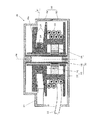
- 4 is a cross-sectional view taken along line AA in FIG.
- the cord reel device 20 includes a drawer cord 22, an internal cord 26, a cord reel 30, a reel case 50, and a stopper mechanism (not shown).
- the cord reel 30 includes a fixed shaft 32, a spiral spring 38, and a reel body 40.
- the spiral spring 38 connects the fixed shaft 32 and the reel body 40, and generates a restoring force for rewinding the drawn out cord 22.
- the reel body 40 includes a first reel body 42 and a second reel body 46 that are arranged coaxially.
- the first and second reel bodies 42 and 46 are formed as an integrally molded product of resin, and are held on the fixed shaft 32 in a rotatable state.
- the first reel body 42 has the lead cord 22 wound thereon.
- the inner reel 26 is wound around the second reel body 46.
- the 1st reel body 42 and the 2nd reel body 46 are connected in the direction of the rotating shaft 48 so that each rotating shaft 48 may correspond.
- the cord reel device 20 of the present embodiment the first reel body 42 and the second reel body 46 are connected in parallel in the extending direction of the fixed shaft 32.
- the second reel body 46 is provided with a side wall 47 erected from the winding surface 46a around which the inner cord 26 is wound toward the radially outer side.
- the side wall 47 is disposed so as to be inclined at a predetermined angle with respect to the winding direction of the inner cord 26 (perpendicular direction of the rotating shaft 48).
- the predetermined angle indicating the inclination angle of the side wall 47 is preferably 3 degrees or more and 10 degrees or less. In the present embodiment, the inclination angle of the side wall 47 is set to 6 degrees.
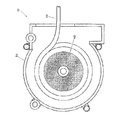
- FIG. 5 is a cross-sectional view of the drawer cord 22 wound around the first reel body 42 of the cord reel device 20 according to the present embodiment as viewed from the first reel body 42 side.
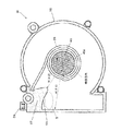
- 6 is a cross-sectional view of the internal cord 26 wound around the second reel body 46 of the cord reel device 20 of FIG. 5 as viewed from the second reel body 46 side.
- the drawer cord 22 is a cord that can be pulled out from the cord reel device 20 and connected to the handset 14.
- chord 22 is a code
- a plug 23 (see FIG. 2) for connecting to the handset 14 is attached to the first end of the lead cord 22.
- the second end opposite to the first end of the lead cord 22 (hereinafter referred to as “base end of the lead cord 22”) is a first reel body 42. It is fixed to.
- the drawer cord 22 is wound around the first reel body 42 so as to be pulled out, and can be pulled out from the reel case 50 against the restoring force of the spiral spring 38 shown in FIG. Further, when the drawer cord 22 is pulled out to an arbitrary length, it is held in a state of being pulled out by a stopper mechanism (not shown). Further, by gently pulling the drawn cord 22 held in the drawn state, the stopper mechanism is released, and the drawn cord 22 is rewound onto the first reel body 42 by the restoring force of the spiral spring 38.
- the inner cord 26 is a flat cord that is about half as long as the lead cord 22 and has a thin cross-sectional shape.
- the first end portion of the inner cord 26 is connected to a connector 58 fixed to the reel case 50 at a position on the inner wall side of the second case 56 (upper left portion in the figure), as shown in FIG. Yes.
- a second end opposite to the first end of the inner cord 26 (hereinafter referred to as “base end portion of the inner cord 26”) is connected to the second reel body 46.
- the inner cord 26 is wound around the second reel body 46 in the same direction as the winding direction of the drawer cord 22.
- the reel case 50 is a resin case, and includes a first case 52 that covers the first reel body 42 side, and a second case 56 that covers the second reel body 46 side.
- the reel case 50 can rotate the reel body 40 by fitting the first case 52 and the second case 56 in a state where the first case 52 and the second case 56 are attached to the fixed shaft 32. Enclose in a safe state.
- the reel case 50 includes the first reel body 42 and the second reel body 46 in a rotatable state, and allows the inner cord 26 to float when the drawer cord 22 is wound. Is formed inside.
- the second case 56 is formed with a protruding portion 57 that protrudes in the winding space in the reel case 50.
- the convex portion 57 is integrally formed with the second case 56 with resin as a part of the second case 56 (reel case 50). Further, the convex portion 57 is provided so as to protrude toward the rotation axis of the first and second reel bodies 42 and 46. Further, as shown in FIG. 6, the convex portion 57 is a position where the first end portion of the inner cord 26 is fixed in the winding space of the inner cord 26 formed in the second case 56 (reel case 50). Is provided on the upstream side in the winding direction of the internal cord 26 (clockwise in the figure).
- the winding direction of the internal cord 26 refers to the direction in which the internal cord 26 is wound when the drawn cord 22 drawn to the outside is wound on the first reel body 42 (see the dotted arrow in FIG. 6). ). More specifically, the convex portion 57 is located on the inner side of the winding space (on the rotating shaft side of the second reel body 46) so that the slack portion of the inner cord 26 generated when the drawer cord 22 is inserted and removed is not increased. Is provided at a predetermined position in order to be pressed toward the front.
- a convex portion 57 is provided at a position on the upstream side in the winding direction. Note that the operation and effect of the present disclosure resulting from the provision of the convex portion 57 will be described in detail later.
- a part of the wall surface forming the convex portion 57 is provided with a cord locking wall 59 that forms a pocket space S (see FIG. 6) for locking the slack portion of the internal cord 26.
- the cord locking wall 59 is a part of the wall surface constituting the convex portion 57 described above, and is formed in a substantially arc shape in a side view as shown in FIG.
- the cord locking wall 59 is provided in a shape in which the moving radius R ( ⁇ ) from the rotation axis of the second reel body 46 to the boundary of the winding space decreases discontinuously in the declination direction ⁇ .
- the cord locking wall 59 is wound around the inner cord 26 in the range of the deflection angle ⁇ 1 to the deflection angle ⁇ 2 in the direction in which the second reel body 46 rotates when the drawer cord 22 is rewound.
- the moving radius R ( ⁇ ) to the boundary of the rotation space is formed so as to decrease discontinuously from R ( ⁇ 1) to R ( ⁇ 2).
- a pocket space S for holding the folded portion of the slacking inner cord 26 is formed in the upstream portion of the convex portion 57 in the winding direction. Is done.
- the detailed operation and effect of providing the cord locking wall 59 in the cord reel device 20 of this embodiment will be described in detail later.
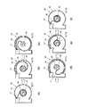
- FIGS. 7A to 7F are cross-sectional views of the internal cord 26 as seen from the second reel body 46 side in order to explain the drawing operation of the cord reel device 20 in the present embodiment.
- FIG. 7A shows the state S71 of the internal cord 26 before the lead cord 22 is pulled out.
- the drawing cord 22 starts to be pulled out against the restoring force of the spiral spring 38 from this state S71, the inner cord 26 begins to be unwound in order from the side connected to the connector 58.
- the part where the inner cord 26 is unfolded extends to the vicinity of the inner wall surface of the second case 56 in the winding space of the inner cord 26 (state S72).
- the turning point P moves in the same direction as the rotation direction of the second reel body 46 (state S75).
- the internal cord 26 is wound around the second reel body 46 in the opposite direction to the state S71 (state S76). Then, when the drawing operation of the drawing cord 22 is stopped, the stopper mechanism holds this state S76.
- FIGS. 8A to 8F are cross-sectional views of the inner cord 26 viewed from the second reel body 46 side in order to explain the rewinding operation of the cord reel device 20 of the present embodiment.
- the drawing cord 22 When the drawing cord 22 is further rewound, it starts to be wound around the second reel body 46 in order from the second end (base end) side of the inner cord 26. At this time, the winding direction is opposite to the direction of the state S81. Then, as shown in FIG. 8D, a turning point P is generated between the portion where the inner cord 26 is wound and the portion where the inner cord 26 is unwound (state S84). As shown in FIG. 8E, the turning point P moves in the same direction as the direction in which the second reel body 46 rotates (state S85).
- FIGS. 9A to 9D show the internal cord 26 viewed from the second reel body 46 side in order to explain another rewinding operation of the cord reel device 20 in the present embodiment. It is sectional drawing.
- the convex part 57 which protrudes in the winding space in the 2nd case 56 is provided.
- the convex part 57 has the substantially arc-shaped code
- the side wall 47 of the second reel body 46 is moved approximately with respect to the winding direction of the inner cord 26 (the perpendicular direction of the rotating shaft 48). Tilt 6 degrees. That is, in the present embodiment, the side wall 47 of the second reel body 46 is inclined with respect to the winding direction of the inner cord 26 (the perpendicular direction of the rotating shaft 48).
- the inner cord 26 is wound up, friction between the inner cord 26 and the side wall 47 is increased, and the inner cord 26 is drawn inside the winding space (in the direction of the rotation axis of the second reel body 46). Can be prevented.
- the convex portion 57 protruding into the winding space is provided in the second case 56.
- the convex portion 57 has a substantially arc-shaped cord engagement in which the moving radius R to the boundary of the winding space of the inner cord 26 decreases discontinuously when the deflection angle is changed in the direction of rewinding the lead cord 22.
- a stop wall 59 is provided. For this reason, it is possible to effectively suppress the turning point P of the inner cord 26 from moving beyond the cord locking wall 59.
- the side wall 47 of the second reel body 46 is tilted at a predetermined angle (about 6 degrees in the present embodiment) with respect to the normal of the rotating shaft 48. For this reason, it is possible to effectively suppress the turning point P from moving through the gap between the convex portion 57 and the second reel body 46. Therefore, it is possible to provide a highly reliable cord reel device capable of preventing the winding point P from being caught between the inner cords and causing the winding to be effectively prevented. Can do.
- cord reel device connected to the handset has been described as an example, but the present disclosure is not limited to this.
- it can be used as a cord reel device that winds and stores a headphone cord, an electrical wiring cord, an optical cord, and other various cords.
- This disclosure is useful as a highly reliable cord reel device that can effectively suppress the occurrence of winding failure.
Landscapes
- Storing, Repeated Paying-Out, And Re-Storing Of Elongated Articles (AREA)
Abstract
Priority Applications (2)
| Application Number | Priority Date | Filing Date | Title |
|---|---|---|---|
| US14/385,773 US9586787B2 (en) | 2012-03-23 | 2013-03-08 | Cord reel device |
| JP2014505999A JP6115870B2 (ja) | 2012-03-23 | 2013-03-08 | コードリール装置 |
Applications Claiming Priority (2)
| Application Number | Priority Date | Filing Date | Title |
|---|---|---|---|
| JP2012066599 | 2012-03-23 | ||
| JP2012-066599 | 2012-03-23 |
Publications (1)
| Publication Number | Publication Date |
|---|---|
| WO2013140736A1 true WO2013140736A1 (fr) | 2013-09-26 |
Family
ID=49222219
Family Applications (1)
| Application Number | Title | Priority Date | Filing Date |
|---|---|---|---|
| PCT/JP2013/001522 Ceased WO2013140736A1 (fr) | 2012-03-23 | 2013-03-08 | Dispositif enrouleur de câble |
Country Status (3)
| Country | Link |
|---|---|
| US (1) | US9586787B2 (fr) |
| JP (1) | JP6115870B2 (fr) |
| WO (1) | WO2013140736A1 (fr) |
Families Citing this family (4)
| Publication number | Priority date | Publication date | Assignee | Title |
|---|---|---|---|---|
| CN107662840B (zh) * | 2016-07-29 | 2019-07-23 | 上海微电子装备(集团)股份有限公司 | 一种运动线缆收线装置 |
| US10875740B1 (en) | 2019-04-02 | 2020-12-29 | Kevin Santaite | Wall-mounted retractable holster |
| US11563316B2 (en) * | 2020-02-18 | 2023-01-24 | Panasonic Intellectual Property Management Co., Ltd. | System including management apparatus and electronic device connected to cord reel |
| US11316312B2 (en) * | 2020-09-29 | 2022-04-26 | Dell Products L.P. | Low profile circular dongle |
Citations (3)
| Publication number | Priority date | Publication date | Assignee | Title |
|---|---|---|---|---|
| US6616080B1 (en) * | 1999-04-28 | 2003-09-09 | Speculative Product Design, Inc. | Retractable cord device |
| US7216665B1 (en) * | 2004-06-18 | 2007-05-15 | Sub-Q, Llc | Retractable reel |
| JP2009247598A (ja) * | 2008-04-07 | 2009-10-29 | Panasonic Corp | 電源コード巻取り装置及びそれを用いた電気掃除機 |
Family Cites Families (14)
| Publication number | Priority date | Publication date | Assignee | Title |
|---|---|---|---|---|
| US2912140A (en) * | 1957-03-07 | 1959-11-10 | Kleen Stik Products Inc | Label dispenser |
| US4590089A (en) * | 1979-04-30 | 1986-05-20 | Ndm Corporation | Medical electrodes and dispensing conditioner therefor |
| US4384688A (en) * | 1981-05-26 | 1983-05-24 | Warren F. B. Lindsley | Self-storing cord and hose reel assemblies |
| US4824517A (en) * | 1987-08-20 | 1989-04-25 | Dennison Manufacturing Company | Multipurpose dispenser |
| JPH01160685U (fr) * | 1988-04-28 | 1989-11-08 | ||
| US5094396B1 (en) * | 1988-11-04 | 1997-05-27 | Telefonix Inc | Retractable reel assembly for telephone extension cord |
| DE29580194U1 (de) | 1994-04-25 | 1997-02-20 | Claircom Communications Group, Inc., Seattle, Wash. | Flugzeugtelefon |
| EP0951748B1 (fr) * | 1997-01-07 | 2007-11-14 | Telefonix, Inc. | Devidoir retractable comprenant un mecanisme a cliquet cannele |
| JP2001089037A (ja) * | 1999-09-22 | 2001-04-03 | Kanda Tsushin Kogyo Co Ltd | コード巻き取り装置 |
| US6446898B1 (en) * | 2000-02-28 | 2002-09-10 | Lih-Jiuan Hwang | Wire collector |
| US6497378B1 (en) * | 2001-07-19 | 2002-12-24 | Sheng Hsin Liao | Wire-winding mechanism having dual wire outlets |
| US7104491B2 (en) * | 2002-02-07 | 2006-09-12 | Vinding Donald R | Retractable reel for flexible tubing |
| US8387763B2 (en) * | 2010-11-22 | 2013-03-05 | Telefonix, Inc. | Retractable cord reel |
| US9221652B2 (en) * | 2013-03-18 | 2015-12-29 | Response Engineering, Inc. | Rotatable cable guide for retractable cord reel |
-
2013
- 2013-03-08 WO PCT/JP2013/001522 patent/WO2013140736A1/fr not_active Ceased
- 2013-03-08 US US14/385,773 patent/US9586787B2/en active Active
- 2013-03-08 JP JP2014505999A patent/JP6115870B2/ja active Active
Patent Citations (3)
| Publication number | Priority date | Publication date | Assignee | Title |
|---|---|---|---|---|
| US6616080B1 (en) * | 1999-04-28 | 2003-09-09 | Speculative Product Design, Inc. | Retractable cord device |
| US7216665B1 (en) * | 2004-06-18 | 2007-05-15 | Sub-Q, Llc | Retractable reel |
| JP2009247598A (ja) * | 2008-04-07 | 2009-10-29 | Panasonic Corp | 電源コード巻取り装置及びそれを用いた電気掃除機 |
Also Published As
| Publication number | Publication date |
|---|---|
| US20150108265A1 (en) | 2015-04-23 |
| JPWO2013140736A1 (ja) | 2015-08-03 |
| JP6115870B2 (ja) | 2017-04-19 |
| US9586787B2 (en) | 2017-03-07 |
Similar Documents
| Publication | Publication Date | Title |
|---|---|---|
| EP2719042B1 (fr) | Dispositif d'extension de câble électrique pouvant être ré-enroulé | |
| JP6115870B2 (ja) | コードリール装置 | |
| US10483699B2 (en) | Retractable cable and cable rewind spool configuration | |
| CN104412475B (zh) | 具有中心进料部的缆线存储线轴 | |
| CN102317189B (zh) | 软线卷轴 | |
| EP2645508B1 (fr) | Dispositif de bobinage de câble et mécanisme associé de fixation et d'enroulement | |
| CN101459328A (zh) | 可减少摩擦阻力的电源线卷收装置 | |
| JP2002544093A (ja) | 巻き取り式コード装置 | |
| US9567186B2 (en) | Motorized hose reel with anti-rotation interlock | |
| JP2013532399A (ja) | ユーザインターフェースデバイスのための展開システム及び方法 | |
| CN103183260A (zh) | 容置装置 | |
| US10170902B2 (en) | Extension and retraction device and method | |
| KR101752771B1 (ko) | 이어폰 줄 자동 감김 장치 | |
| WO2011122470A1 (fr) | Dispositif raccord rotatif | |
| WO2011122469A1 (fr) | Dispositif raccord rotatif | |
| US20200223657A1 (en) | Automatic Winding Device | |
| CN103210633B (zh) | 用于运输设备上音频装置的收纳式耳机 | |
| US20190276270A1 (en) | Attachment structure for cord reel, and apparatus including cord reel and holder | |
| CN216355150U (zh) | 一种车载伸缩线装置 | |
| JP3255621U (ja) | ケーブル巻き取り装置 | |
| JP4101031B2 (ja) | 継電装置 | |
| CN201174473Y (zh) | 转换接头的卷线装置 | |
| US8262009B2 (en) | System for electrical cable management in limited rotation applications | |
| WO2005048649A1 (fr) | Moyen de rangement de cable | |
| JP2002096976A (ja) | 巻き取りケーブル装置 |
Legal Events
| Date | Code | Title | Description |
|---|---|---|---|
| 121 | Ep: the epo has been informed by wipo that ep was designated in this application |
Ref document number: 13764999 Country of ref document: EP Kind code of ref document: A1 |
|
| ENP | Entry into the national phase |
Ref document number: 2014505999 Country of ref document: JP Kind code of ref document: A |
|
| WWE | Wipo information: entry into national phase |
Ref document number: 14385773 Country of ref document: US |
|
| NENP | Non-entry into the national phase |
Ref country code: DE |
|
| 122 | Ep: pct application non-entry in european phase |
Ref document number: 13764999 Country of ref document: EP Kind code of ref document: A1 |